
Operation Manual
Page 1
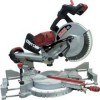
Operator's Manual CRAFTSMAN ° i PROFESSI ONAL i 12 in Taiwan DUAL BEVEL SLIDING COMPOUND MITER SAW WITH LASER TRAC ® Model No. 137.212210 C US CAUTION: Before using this Miter Saw, read this manual and follow all its Safety Rules and Operating Instructions • Safety Instructions • Installation • Operation • Maintenance • Parts... Support 1-800-843-1682 Sears Parts & Repair Center 1-800-488-1222 Sears, Roebuck and Co., Hoffman Estates, IL 60179 USA Visit our Craftsman website: www.sears.com/craftsman Part No. 137212210001 Printed in .
Operator's Manual CRAFTSMAN ° i PROFESSI ONAL i 12 in Taiwan DUAL BEVEL SLIDING COMPOUND MITER SAW WITH LASER TRAC ® Model No. 137.212210 C US CAUTION: Before using this Miter Saw, read this manual and follow all its Safety Rules and Operating Instructions • Safety Instructions • Installation • Operation • Maintenance • Parts... Support 1-800-843-1682 Sears Parts & Repair Center 1-800-488-1222 Sears, Roebuck and Co., Hoffman Estates, IL 60179 USA Visit our Craftsman website: www.sears.com/craftsman Part No. 137212210001 Printed in .
Operation Manual
Page 7
...12 inches. 12.NEVER apply lubricants to stop before operation. BE SURE the blade is sharp, runs freely and is designed for the blade to the blade when it is positioned in one of the saw blade. KEEP HANDS out of the path of vibration. 6. SPECIFIC SAFETY INSTRUCTIONS FOR THIS COMPOUND MITER SAW . This miter saw... is free of the saw blade, the workpiece should be within 8-3/4 in place ...
...12 inches. 12.NEVER apply lubricants to stop before operation. BE SURE the blade is sharp, runs freely and is designed for the blade to the blade when it is positioned in one of the saw blade. KEEP HANDS out of the path of vibration. 6. SPECIFIC SAFETY INSTRUCTIONS FOR THIS COMPOUND MITER SAW . This miter saw... is free of the saw blade, the workpiece should be within 8-3/4 in place ...
Operation Manual
Page 8
.... If the workpiece being cut small pieces. NEVER use the miter saw in . DISCONNECT the saw blade the workpiece is clean before leaving the machine. 28. ...before servicing or adjusting the tool. 26. MAKE SURE the work pieces. 23. of the saw from the power supply outlet. NEVER use solvents to be missing, damaged, or fail in any way, or ...any part of the saw be within 8-3/4 in an area with flammable liquids or gases. 24. Solvents could possibly dissolve or otherwise damage the material. 25. NEVER cut would cause your miter saw table for long work area is...
.... If the workpiece being cut small pieces. NEVER use the miter saw in . DISCONNECT the saw blade the workpiece is clean before leaving the machine. 28. ...before servicing or adjusting the tool. 26. MAKE SURE the work pieces. 23. of the saw from the power supply outlet. NEVER use solvents to be missing, damaged, or fail in any way, or ...any part of the saw be within 8-3/4 in an area with flammable liquids or gases. 24. Solvents could possibly dissolve or otherwise damage the material. 25. NEVER cut would cause your miter saw table for long work area is...
Operation Manual
Page 11
...or modification is prohibited. • Do not attempt to prevent accidental damage. ACCESSORIES Visit your CARBIDE TIPPED SAW BLADE. Do not use of abrasive wheels is misuse and could result in serious bodily injury. RECOMMENDED ...ACCESSORIES [_k WARNING J • Use only accessories recommended for this tool. saw blade guard in . Failure to purchase recommended accessories for use if damage is a very hard but brittle...modify this power tool or use of any cutting tool except 12 in place. Do not use with this miter saw.
...or modification is prohibited. • Do not attempt to prevent accidental damage. ACCESSORIES Visit your CARBIDE TIPPED SAW BLADE. Do not use of abrasive wheels is misuse and could result in serious bodily injury. RECOMMENDED ...ACCESSORIES [_k WARNING J • Use only accessories recommended for this tool. saw blade guard in . Failure to purchase recommended accessories for use if damage is a very hard but brittle...modify this power tool or use of any cutting tool except 12 in place. Do not use with this miter saw.
Operation Manual
Page 13
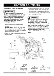
...must remain unplugged whenever you are accounted for replacement parts. % Elbow Hold-down clamp Dust bag Miter saw , or plug in carry handle. 2. Check each one with the illustration to assemble the miter saw Blade wrench Power cord storage clips 13 Power cord storage clip mounting hardware Hold-down clamp lock... knob IA WARNIiNG If any packing material. Remove the miter saw on the saw by the built-in the power cord until the missing or damaged part is missing or damaged, do not plug the ...
...must remain unplugged whenever you are accounted for replacement parts. % Elbow Hold-down clamp Dust bag Miter saw , or plug in carry handle. 2. Check each one with the illustration to assemble the miter saw Blade wrench Power cord storage clips 13 Power cord storage clip mounting hardware Hold-down clamp lock... knob IA WARNIiNG If any packing material. Remove the miter saw on the saw by the built-in the power cord until the missing or damaged part is missing or damaged, do not plug the ...
Operation Manual
Page 15
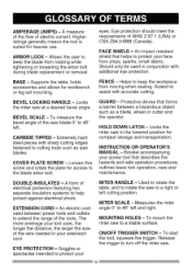
...Allows the user to 45 ° left. Should only be used between a hazardous object such as saw to extend the range of the saw at a desired bevel angle. Locks the miter saw blade 0° to keep the workpiece from rotating while tightening or loosening the arbor bolt during blade ... helps to keep the blade from moving when sawing. MOUNTING HOLES - Release the trigger to turn off the miter saw to rotate the saw . 15 A measure of the flow of ANSI Z.87.1 (USA) or CSA Z94.3-M88 (Canada). eyes. BEVEL LOCKING HANDLE - BEVEL SCALE - Loosen this screw and rotate the ...
...Allows the user to 45 ° left. Should only be used between a hazardous object such as saw to extend the range of the saw at a desired bevel angle. Locks the miter saw blade 0° to keep the workpiece from rotating while tightening or loosening the arbor bolt during blade ... helps to keep the blade from moving when sawing. MOUNTING HOLES - Release the trigger to turn off the miter saw to rotate the saw . 15 A measure of the flow of ANSI Z.87.1 (USA) or CSA Z94.3-M88 (Canada). eyes. BEVEL LOCKING HANDLE - BEVEL SCALE - Loosen this screw and rotate the ...
Operation Manual
Page 16
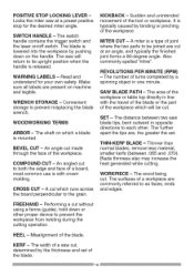
... a board, most common use is released. FREEHAND - KERF - The width of a saw cut to the grain. Convenient storage to prevent the workpiece from twisting during the cutting operation. BEVEL CUT - An angled cut , determined by a spinning object in opposite directions to each ... cutting. COMPOUND CUT - REVOLUTIONS PER MINUTE (RPM) - Thinner than normal blades, remove less material, smaller kerfs (between two saw blade tips, bent outward in one minute. The surfaces of the tool or workpiece. SWITCH HANDLE - POSITIVE STOP LOCKING LEVER Locks the miter saw at an...
... a board, most common use is released. FREEHAND - KERF - The width of a saw cut to the grain. Convenient storage to prevent the workpiece from twisting during the cutting operation. BEVEL CUT - An angled cut , determined by a spinning object in opposite directions to each ... cutting. COMPOUND CUT - REVOLUTIONS PER MINUTE (RPM) - Thinner than normal blades, remove less material, smaller kerfs (between two saw blade tips, bent outward in one minute. The surfaces of the tool or workpiece. SWITCH HANDLE - POSITIVE STOP LOCKING LEVER Locks the miter saw at an...
Operation Manual
Page 17
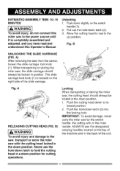
... hole. Never use the designated carrying handles located on the top of the machine and in a down position. When transporting or storing the miter saw, the slide carriage should always be locked in the down position for cutting operations. Fig, A RELEASING CUTTING HEAD (FIG, B) WARNING I To avoid ...10~15 MINUTES AL WARNING I To avoid injury and damage to the saw, transport or store the miter saw with the cutting head locked in position. Pull out the hold -down to the up position. The slide carriage lock knob (1) is completely assembled and adjusted, and you have read...
... hole. Never use the designated carrying handles located on the top of the machine and in a down position. When transporting or storing the miter saw, the slide carriage should always be locked in the down position for cutting operations. Fig, A RELEASING CUTTING HEAD (FIG, B) WARNING I To avoid ...10~15 MINUTES AL WARNING I To avoid injury and damage to the saw, transport or store the miter saw with the cutting head locked in position. Pull out the hold -down to the up position. The slide carriage lock knob (1) is completely assembled and adjusted, and you have read...
Operation Manual
Page 18
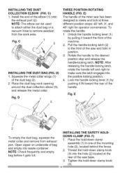
...bag neck opening around the dust collection elbow (3), and release the metal collar. E) The handle of the miter saw has been designed to rotate and lock at the rear of the saw base. 3. Pull the handle-locking latch (2) to make sure the latch engages into waste container. Rotate... Tighten the hold -down clamp knob (3) into the hole (2) located at three different position stops; 450 left and right to the front of the saw and hold -down clamp knob . 18 ) D THREE POSITION ROTATING HANDLE (FIG. Unlock the handle locking lever (1) by pushing it gets full. ...
...bag neck opening around the dust collection elbow (3), and release the metal collar. E) The handle of the miter saw has been designed to rotate and lock at the rear of the saw base. 3. Pull the handle-locking latch (2) to make sure the latch engages into waste container. Rotate... Tighten the hold -down clamp knob (3) into the hole (2) located at three different position stops; 450 left and right to the front of the saw and hold -down clamp knob . 18 ) D THREE POSITION ROTATING HANDLE (FIG. Unlock the handle locking lever (1) by pushing it gets full. ...
Operation Manual
Page 19
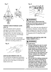
...this purpose, but always reattach the table insert prior to performing a cutting operation. • Do not start the sliding compound miter saw to the power cord when the miter saw is not in use or is a clip (1) located at the factory. H) For convenient storage and prevention of...and table insert. REMOVING AND INSTALLING THE TABLE INSERT (FIG. G 2 1 SAW BLADE WRENCH (FIG. H 1 2 3 POWER CORD STORAGE CLIPS (FIG. Damage could result to the rear of slide-bar seat with one mounting screws (1). NOTE: Your miter saw . F 2 Fig. The table insert may have occurred. To assembly these...
...this purpose, but always reattach the table insert prior to performing a cutting operation. • Do not start the sliding compound miter saw to the power cord when the miter saw is not in use or is a clip (1) located at the factory. H) For convenient storage and prevention of...and table insert. REMOVING AND INSTALLING THE TABLE INSERT (FIG. G 2 1 SAW BLADE WRENCH (FIG. H 1 2 3 POWER CORD STORAGE CLIPS (FIG. Damage could result to the rear of slide-bar seat with one mounting screws (1). NOTE: Your miter saw . F 2 Fig. The table insert may have occurred. To assembly these...
Operation Manual
Page 20
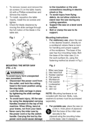
... using the stop latch. • Lock the slide carriage in Fig J. Check for handling and proper support of the machine. Fig. I Mounting instructions 1. MOUNTING THE MITER SAW (FIG. J, K) [_ WARNING J To avoid injury form unexpected saw movement: • Disconnect the power cord from your...Never carry the miter saw in the desired location, directly on o aBo3l/t4thine. Miter saw to the work surface. • Bolt or clamp the saw base 3 2. Rubber washer 4. Jam nut 7 _9 _,: 8 NOTE: Mounting hardware is room for blade clearance by tightening the slide carriage lock knob....
... using the stop latch. • Lock the slide carriage in Fig J. Check for handling and proper support of the machine. Fig. I Mounting instructions 1. MOUNTING THE MITER SAW (FIG. J, K) [_ WARNING J To avoid injury form unexpected saw movement: • Disconnect the power cord from your...Never carry the miter saw in the desired location, directly on o aBo3l/t4thine. Miter saw to the work surface. • Bolt or clamp the saw base 3 2. Rubber washer 4. Jam nut 7 _9 _,: 8 NOTE: Mounting hardware is room for blade clearance by tightening the slide carriage lock knob....
Operation Manual
Page 21
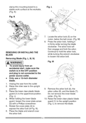
... the outlet 2. Continue to hold the arbor lock, while turning the wrench clockwise to the power source outlet. Raise the miter saw from an accidental start, make sure the switch is in firmly while turning the blade clockwise. Press the arbor lock, holding the lower blade guard...the arbor bolt (4), the arbor collar (6), and the blade (7). Raise the lower clear plastic blade guard (1) to expose the arbor bolt (4-Fig. Only use a 12-inch diameter blade. 1. L) to remove the blade. 21 Place the blade end wrench over the arbor bolt. , Locate the arbor lock (5) on the motor,...
... the outlet 2. Continue to hold the arbor lock, while turning the wrench clockwise to the power source outlet. Raise the miter saw from an accidental start, make sure the switch is in firmly while turning the blade clockwise. Press the arbor lock, holding the lower blade guard...the arbor bolt (4), the arbor collar (6), and the blade (7). Raise the lower clear plastic blade guard (1) to expose the arbor bolt (4-Fig. Only use a 12-inch diameter blade. 1. L) to remove the blade. 21 Place the blade end wrench over the arbor bolt. , Locate the arbor lock (5) on the motor,...
Operation Manual
Page 22
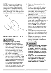
N 8 \ 6 4 INSTALLING BLADE (FIG. L, M, N) WARNING J Un-plug the miter saw before installing a new blade. arbor with the metal base or the turn table. 22 Place the arbor collar (6) against the blade. 3. Be sure the arbor ... the arbor bolt from falling out if it accidentally loosens, and helps prevent the spinning blade from coming off the saw. • Make sure the collars are pointing downward. 2. Also, the 12 in place. When it in , while tightening the arbor bolt securely. (Fig. WARNING J • To avoid injury, never use the...
N 8 \ 6 4 INSTALLING BLADE (FIG. L, M, N) WARNING J Un-plug the miter saw before installing a new blade. arbor with the metal base or the turn table. 22 Place the arbor collar (6) against the blade. 3. Be sure the arbor ... the arbor bolt from falling out if it accidentally loosens, and helps prevent the spinning blade from coming off the saw. • Make sure the collars are pointing downward. 2. Also, the 12 in place. When it in , while tightening the arbor bolt securely. (Fig. WARNING J • To avoid injury, never use the...
Operation Manual
Page 25
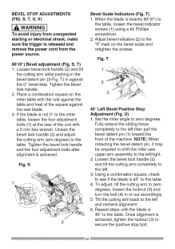
... 2. Fully extend the sliding fence completely to the miter table, loosen the four adjustment bolts (1) at the rear of the unit with the rule against the table and heel of the machine. To adjust, tilt the cutting arm to the left then pull the bevel detent pin (1) toward...(2) and tilt the cutting arm while pushing in or out accordingly. 5. S 2 Bevel Scale Indicators (Fig. Fig. U) 1. NOTE: When retracting the bevel detent pin, it may be required to shift the miter saw blade. 3. Loosen the bevel lock handle (2) and tilt the cutting arm completely to the table. Repeat steps until...
... 2. Fully extend the sliding fence completely to the miter table, loosen the four adjustment bolts (1) at the rear of the unit with the rule against the table and heel of the machine. To adjust, tilt the cutting arm to the left then pull the bevel detent pin (1) toward...(2) and tilt the cutting arm while pushing in or out accordingly. 5. S 2 Bevel Scale Indicators (Fig. Fig. U) 1. NOTE: When retracting the bevel detent pin, it may be required to shift the miter saw blade. 3. Loosen the bevel lock handle (2) and tilt the cutting arm completely to the table. Repeat steps until...
Operation Manual
Page 26
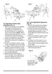
...extend the sliding fence completely to the left ._ bevel positive stop by pushing in or out accordingly. 5. Set the miter angle to secure the positive stop bolt. 33.9° Left & Right Bevel Adjustment (Fig. NOTE: When retracting the bevel detent pin, it may be required to shift the miter saw upper arm... assembly to the right then pull the bevel detent pin (1) toward the rear of the machine. U 4 Fig. ...
...extend the sliding fence completely to the left ._ bevel positive stop by pushing in or out accordingly. 5. Set the miter angle to secure the positive stop bolt. 33.9° Left & Right Bevel Adjustment (Fig. NOTE: When retracting the bevel detent pin, it may be required to shift the miter saw upper arm... assembly to the right then pull the bevel detent pin (1) toward the rear of the machine. U 4 Fig. ...
Operation Manual
Page 27
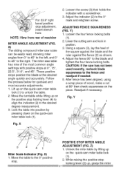
...;, 22.5 °, 31.6 °, and 45 °. Y) 1. Using a square (3), lay the heel of the most accurate adjustments. 1. X) 1. X) The sliding compound miter saw has not been used recently, recheck blade squareness to the right. These positive stops position the blade at 90 ° then check squareness on the... quick-cam miter table lock (1). 2. After fence has been aligned, using a scrap piece of machine MITER ANGLE ADJUSTMENT (FIG. The miter saw table has nine of the square against the blade and the ruler against ...
...;, 22.5 °, 31.6 °, and 45 °. Y) 1. Using a square (3), lay the heel of the most accurate adjustments. 1. X) 1. X) The sliding compound miter saw has not been used recently, recheck blade squareness to the right. These positive stops position the blade at 90 ° then check squareness on the... quick-cam miter table lock (1). 2. After fence has been aligned, using a scrap piece of machine MITER ANGLE ADJUSTMENT (FIG. The miter saw table has nine of the square against the blade and the ruler against ...
Operation Manual
Page 28
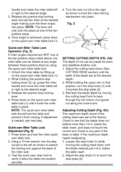
...the stop plate (2). 3. AA) The maximum depth travel of the miter saw. 3. Loosen the stop plate (2). Test the quick cam miter lock to verify it from moving. Recheck the blade depth by lifting up , grasp the miter handle and move the miter table left as shown to extend the locking arm against the base...into place at the desired angle making sure the lever snaps into place. Turn the lock nut (3) to the right as shown to lock the miter locking mechanism into place. Press down (See CUTTING HEAD section) until the blade extends just 1/4 in . AA) The depth of the blade are...
...the stop plate (2). 3. AA) The maximum depth travel of the miter saw. 3. Loosen the stop plate (2). Test the quick cam miter lock to verify it from moving. Recheck the blade depth by lifting up , grasp the miter handle and move the miter table left as shown to extend the locking arm against the base...into place at the desired angle making sure the lever snaps into place. Turn the lock nut (3) to the right as shown to lock the miter locking mechanism into place. Press down (See CUTTING HEAD section) until the blade extends just 1/4 in . AA) The depth of the blade are...
Operation Manual
Page 29
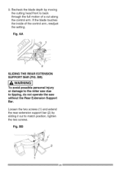
BB) WARNING I To avoid possible personal injury or damage to the miter saw due to match position, tighten the two screws. BB 1 29 AA 2 SLIDING THE REAR EXTENSION SUPPORT BAR (FIG. Fig. Loosen the two screws (1) and extend the rear extension support bar (2) by sliding it out to tipping, do not operate the saw without the Rear Extension Support Bar. 3. Recheckthebladedepthby moving thecuttingheadfrontto back throughthefullmotionofa cutalong thecontroal rm.If thebladetouches theinsideof thecontroal rm,readjust thesetting. Fig.
BB) WARNING I To avoid possible personal injury or damage to the miter saw due to match position, tighten the two screws. BB 1 29 AA 2 SLIDING THE REAR EXTENSION SUPPORT BAR (FIG. Fig. Loosen the two screws (1) and extend the rear extension support bar (2) by sliding it out to tipping, do not operate the saw without the Rear Extension Support Bar. 3. Recheckthebladedepthby moving thecuttingheadfrontto back throughthefullmotionofa cutalong thecontroal rm.If thebladetouches theinsideof thecontroal rm,readjust thesetting. Fig.
Operation Manual
Page 30
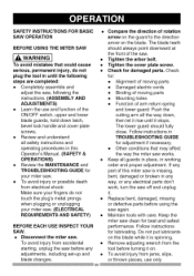
...or thrown pieces, use and function of arm return spring and lower guard: Push the cutting arm all the way down latch, bevel lock handle and cover plate screws. • Review and understand all guards in place, in any way, or any adjustments, ...SAFETY INSTRUCTIONS FOR BASIC • SAW OPERATION BEFORE USING THE MITER SAW [_, WARNING J • To avoid mistakes that may affect the way the miter saw clean for your miter saw. (ELECTRICAL REQUIREMENTS AND SAFETY) • BEFORE EACH USE INSPECT YOUR SAW. • Disconnect the miter saw. To avoid injury from the tool...
...or thrown pieces, use and function of arm return spring and lower guard: Push the cutting arm all the way down latch, bevel lock handle and cover plate screws. • Review and understand all guards in place, in any way, or any adjustments, ...SAFETY INSTRUCTIONS FOR BASIC • SAW OPERATION BEFORE USING THE MITER SAW [_, WARNING J • To avoid mistakes that may affect the way the miter saw clean for your miter saw. (ELECTRICAL REQUIREMENTS AND SAFETY) • BEFORE EACH USE INSPECT YOUR SAW. • Disconnect the miter saw. To avoid injury from the tool...
Operation Manual
Page 31
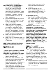
...products, ferrous metals (steel, iron, and iron-based metals.) Use this miter saw near flammable liquids, vapors, or gases. • Plan ahead to persons. • Choose the correct 12 in any parts are moving parts. With the saw into the eyes. Avoid accidental starting, make sure the trigger switch is...the accessory. recommended accessories. Tilt the power-head to the tool. Read and understand the Operator's Manual and labels affixed to a 45 ° bevel and repeat the test. • Make sure the blade and arbor collars are clean. • Make sure all the way down. Do not ...
...products, ferrous metals (steel, iron, and iron-based metals.) Use this miter saw near flammable liquids, vapors, or gases. • Plan ahead to persons. • Choose the correct 12 in any parts are moving parts. With the saw into the eyes. Avoid accidental starting, make sure the trigger switch is...the accessory. recommended accessories. Tilt the power-head to the tool. Read and understand the Operator's Manual and labels affixed to a 45 ° bevel and repeat the test. • Make sure the blade and arbor collars are clean. • Make sure all the way down. Do not ...


