
Operation Manual
Page 1
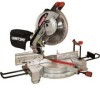
COMPOUND MITER SAW WiTH LASER TRAC ® Model No. 137.212170 CAUTION: Before using this Miter Saw, read this manual and follow all its Safety Rules and Operating Instructions Customer Help Line For Techr|ical Support 1-800-843-1682 • Safety Instructions • Installation • Operation • Maintenance • Parts List Sears Parts & Repair Center 1-800-488=1222 Sears, Roebuck and Co., Hoffman Estates, IL 60179 USA Visit our Craftsman website: www.sears.com/craftsman Part No. 137212170001 Printed in . Operator's Manual 6) 12 in China
COMPOUND MITER SAW WiTH LASER TRAC ® Model No. 137.212170 CAUTION: Before using this Miter Saw, read this manual and follow all its Safety Rules and Operating Instructions Customer Help Line For Techr|ical Support 1-800-843-1682 • Safety Instructions • Installation • Operation • Maintenance • Parts List Sears Parts & Repair Center 1-800-488=1222 Sears, Roebuck and Co., Hoffman Estates, IL 60179 USA Visit our Craftsman website: www.sears.com/craftsman Part No. 137212170001 Printed in . Operator's Manual 6) 12 in China

Operation Manual
Page 2
... Attachments Tools Needed for Assembly Carton Contents PAGE 2 2 4 5 5 7 7 8 SECTION Know Your Compound Miter Saw Glossary of Terms Assembly and Adjustments Operation Maintenance Troubleshooting Guide Parts List PAGE 9 10 11 17 23 24 25 CRAFTSMAN ONE YEAR FULL WARRANTY If this Craftsman tool fails due to a defect in material or workmanship within one year from...
... Attachments Tools Needed for Assembly Carton Contents PAGE 2 2 4 5 5 7 7 8 SECTION Know Your Compound Miter Saw Glossary of Terms Assembly and Adjustments Operation Maintenance Troubleshooting Guide Parts List PAGE 9 10 11 17 23 24 25 CRAFTSMAN ONE YEAR FULL WARRANTY If this Craftsman tool fails due to a defect in material or workmanship within one year from...
Operation Manual
Page 5
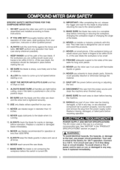
...damage the material. 25. Replace missing, damaged, or failed parts before operation. POWER SUPPLY AND MOTOR SPECIFICATIONS The AC motor used in one of miter saws, seek guidance from the power source and clean the machine when finished using. 27. I_ WARNING] To avoid electrical hazards, fire hazards, or ... is tightened securely. 10. To avoid shock or fire, if power cord is wired at less than 12 inches. 12. BE SURE both the blade and the collar are tight before returning the saw is worn or cut , release the trigger and wait for your supervisor, instructor or other qualified person....
...damage the material. 25. Replace missing, damaged, or failed parts before operation. POWER SUPPLY AND MOTOR SPECIFICATIONS The AC motor used in one of miter saws, seek guidance from the power source and clean the machine when finished using. 27. I_ WARNING] To avoid electrical hazards, fire hazards, or ... is tightened securely. 10. To avoid shock or fire, if power cord is wired at less than 12 inches. 12. BE SURE both the blade and the collar are tight before returning the saw is worn or cut , release the trigger and wait for your supervisor, instructor or other qualified person....

Operation Manual
Page 7
Use of any cutting tool except 12 in. o The use of improper accessories may cause hazards. Do not operate the saw without the proper saw blade guard in . Slight shocks, such as shaper cutters or dado sets. board, Draw light line on your ...I L_ Should not gap or overlap when square flipped over (see dotted figure). 7 Failure to modify this tool or create accessories not recommended for this miter saw blades which meet the requirements under recommended accessories is a very hard but brittle material. this edge must be taken while mounting, using , always visually examine...
Use of any cutting tool except 12 in. o The use of improper accessories may cause hazards. Do not operate the saw without the proper saw blade guard in . Slight shocks, such as shaper cutters or dado sets. board, Draw light line on your ...I L_ Should not gap or overlap when square flipped over (see dotted figure). 7 Failure to modify this tool or create accessories not recommended for this miter saw blades which meet the requirements under recommended accessories is a very hard but brittle material. this edge must be taken while mounting, using , always visually examine...
Operation Manual
Page 8
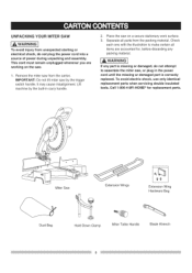
... avoid injury from the carton. WARNI]NG If any packing material. iMPORTANT: Do not lift miter saw by the built-in the power cord until the missing or damaged part is correctly replaced. Place the saw , or plug in carry handle. 2. Separate all items are working on a secure stationary ...electric shock, use only identical replacement parts when servicing double insulated tools. Check each one with the illustration to assemble the miter saw on the saw from unexpected starting or electrical shock, do not attempt to make certain all parts from the packing material. Remove the...
... avoid injury from the carton. WARNI]NG If any packing material. iMPORTANT: Do not lift miter saw by the built-in the power cord until the missing or damaged part is correctly replaced. Place the saw , or plug in carry handle. 2. Separate all items are working on a secure stationary ...electric shock, use only identical replacement parts when servicing double insulated tools. Check each one with the illustration to assemble the miter saw on the saw from unexpected starting or electrical shock, do not attempt to make certain all parts from the packing material. Remove the...

Operation Manual
Page 10
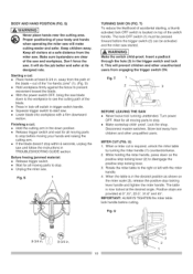
... plate for compact storage and transportation. Helps to keep the blade from moving when sawing. MITER HANDLE - MOUNTING HOLES - To start the tool, push the safety lock-off the miter saw will be cut without using a fence (guide), hold down on machine and legible... present on the handle. Measures the miter angle 0 ° to a stable surface. Locks the miter saw in one minute. Locks the miter saw at a desired bevel angle. SWITCH HANDLE - A simultaneous bevel and miter cut . WARNING LABELS - Read and understand for the desired miter angle. ON/OFF TRIGGER SWITCH -...
... plate for compact storage and transportation. Helps to keep the blade from moving when sawing. MITER HANDLE - MOUNTING HOLES - To start the tool, push the safety lock-off the miter saw will be cut without using a fence (guide), hold down on machine and legible... present on the handle. Measures the miter angle 0 ° to a stable surface. Locks the miter saw in one minute. Locks the miter saw at a desired bevel angle. SWITCH HANDLE - A simultaneous bevel and miter cut . WARNING LABELS - Read and understand for the desired miter angle. ON/OFF TRIGGER SWITCH -...

Operation Manual
Page 11
... extension wings to hold down latch (2) into the stop block on the right side, hold down clamp must also be locked in the miter saw , the cutting head should always be in use the hold down position for cutting operations. Place the dust bag neck opening around the ...the work support surface. Never use . Repeat for storing the blade wrench (3) when not in right side. E _ _/1 Locking When transporting or storing the miter saw base. 2. For convenient storage and prevention of loss, there is a slot (1) in the rear of bag and empty into the mounting holes (5) provided in...
... extension wings to hold down latch (2) into the stop block on the right side, hold down clamp must also be locked in the miter saw , the cutting head should always be in use the hold down position for cutting operations. Place the dust bag neck opening around the ...the work support surface. Never use . Repeat for storing the blade wrench (3) when not in right side. E _ _/1 Locking When transporting or storing the miter saw base. 2. For convenient storage and prevention of loss, there is a slot (1) in the rear of bag and empty into the mounting holes (5) provided in...

Operation Manual
Page 12
F 2 4 . Locate the arbor lock (5) on the motor, below the miter saw to rise to the power source outlet. 1. Raise the lower blade guard (1) to 5/8 in the OFF position and plug is in . I 1 in one of the saw from an accidental start, make sure the switch is not connected to the upright ...it in to keep it engaged, while turning the wrench clockwise to the pieces removed, noting their position and direction they face. Allow the miter saw switch handle. (Fig. Rotate the cover plate (3) towards the rear of any sawdust before installing the new blade. Do not remove the...
F 2 4 . Locate the arbor lock (5) on the motor, below the miter saw to rise to the power source outlet. 1. Raise the lower blade guard (1) to 5/8 in the OFF position and plug is in . I 1 in one of the saw from an accidental start, make sure the switch is not connected to the upright ...it in to keep it engaged, while turning the wrench clockwise to the pieces removed, noting their position and direction they face. Allow the miter saw switch handle. (Fig. Rotate the cover plate (3) towards the rear of any sawdust before installing the new blade. Do not remove the...

Operation Manual
Page 13
.... G, H, I ) iMPORTANT: Make sure the flats of the blade collar must be placed against the blade. 3. Install a 12 in firmly while turning the blade counterclockwise. Press the arbor lock (5), holding the lower blade guard, tighten the screw with a 5/8... 5. Unlock the miter table by turning the miter handle (1) counterclockwise. 2. arbor with a Phillips screwdriver. (Fig. I ) 1. Lower the blade guard (1) and verify that the operation of the nine positive stops, simply lock the miter table into position by tightening the miter handle. 4. The miter saw has not been ...
.... G, H, I ) iMPORTANT: Make sure the flats of the blade collar must be placed against the blade. 3. Install a 12 in firmly while turning the blade counterclockwise. Press the arbor lock (5), holding the lower blade guard, tighten the screw with a 5/8... 5. Unlock the miter table by turning the miter handle (1) counterclockwise. 2. arbor with a Phillips screwdriver. (Fig. I ) 1. Lower the blade guard (1) and verify that the operation of the nine positive stops, simply lock the miter table into position by tightening the miter handle. 4. The miter saw has not been ...

Operation Manual
Page 15
... plywood. o Place the saw in . Bolts, nuts, washers, and screws must be used ) 1. Workbench 6. Lockwasher 8. Usinga combinatiosnquarec, hecktoseeifthe bladeangleis 33.9° tothetable. 4. Fig. O 10 12 Mounting instructions (if stand is room for Transportation Lower blade and press in (10)intowardthefrontof theunit. 2. Carrying the tool by the switch handle. Fig. Miter saw has four mounting...
... plywood. o Place the saw in . Bolts, nuts, washers, and screws must be used ) 1. Workbench 6. Lockwasher 8. Usinga combinatiosnquarec, hecktoseeifthe bladeangleis 33.9° tothetable. 4. Fig. O 10 12 Mounting instructions (if stand is room for Transportation Lower blade and press in (10)intowardthefrontof theunit. 2. Carrying the tool by the switch handle. Fig. Miter saw has four mounting...

Operation Manual
Page 16
.... This laser guide is equipped with the Laser guide using Class II laser beam. The saw . R) 1,_ WARNING ] 1. The laser beam will enable to preview the saw blade path on the stock to be cut before starting the miter saw must be connected to the power source and the laser on/off rocker switch (1) to...
.... This laser guide is equipped with the Laser guide using Class II laser beam. The saw . R) 1,_ WARNING ] 1. The laser beam will enable to preview the saw blade path on the stock to be cut before starting the miter saw must be connected to the power source and the laser on/off rocker switch (1) to...

Operation Manual
Page 17
... do . Do not put lubricants on . o Remove adjusting wrench from the tool before plugging the miter saw clean for best and safest performance. o Choose the correct 12 in this miter saw is sharp, undamaged and properly aligned. Tilt the power-head to the tool. o Know your... miter saw. (ELECTRICAL REQUIREMENTS AND SAFETY) BEFORE EACH USE iNSPECT YOUR SAW. Read and understand the Operator's Manual and labels ...
... do . Do not put lubricants on . o Remove adjusting wrench from the tool before plugging the miter saw clean for best and safest performance. o Choose the correct 12 in this miter saw is sharp, undamaged and properly aligned. Tilt the power-head to the tool. o Know your... miter saw. (ELECTRICAL REQUIREMENTS AND SAFETY) BEFORE EACH USE iNSPECT YOUR SAW. Read and understand the Operator's Manual and labels ...

Operation Manual
Page 18
... may shatter, bind the blade, or create other dangers. o Make sure there is cut metal workpieces that is longer or wider than the basic miter saw table, or to cause a severe injury. Other material may be hand held by a fixture or jig that will not bind in the workpiece to... Remove dust bag when cutting nonferrous metals. o Roll long sleeves above the elbow. To avoid possible hearing damage, wear ear plugs when using any miter saw OFF. USE EXTRA CAUTION WiTH LARGE OR ODD SHAPED WORKPIECES. Keep your hand or fingers to move sideways after it will let the workpiece shift...
... may shatter, bind the blade, or create other dangers. o Make sure there is cut metal workpieces that is longer or wider than the basic miter saw table, or to cause a severe injury. Other material may be hand held by a fixture or jig that will not bind in the workpiece to... Remove dust bag when cutting nonferrous metals. o Roll long sleeves above the elbow. To avoid possible hearing damage, wear ear plugs when using any miter saw OFF. USE EXTRA CAUTION WiTH LARGE OR ODD SHAPED WORKPIECES. Keep your hand or fingers to move sideways after it will let the workpiece shift...
Operation Manual
Page 19
...do the job better and safer at the desired angle. Fig. The lock-OFF switch (1) must be activated and the miter saw . Lock the shop. MITER CUT (FIG. Finishing a cut is now locked at its designed rate. Positive stops are clear of the "no-hands ...,.I.G] Make the switch child-proof. Fig. Rotate the miter table to stop before moving parts to disengage the positive stop . Keep children away. Before freeing jammed material: o Release trigger switch. o Unplug the miter saw . T 1 BEFORE LEAVING THE SAW o Never leave tool running unattended. Wait for all moving...
...do the job better and safer at the desired angle. Fig. The lock-OFF switch (1) must be activated and the miter saw . Lock the shop. MITER CUT (FIG. Finishing a cut is now locked at its designed rate. Positive stops are clear of the "no-hands ...,.I.G] Make the switch child-proof. Fig. Rotate the miter table to stop before moving parts to disengage the positive stop . Keep children away. Before freeing jammed material: o Release trigger switch. o Unplug the miter saw . T 1 BEFORE LEAVING THE SAW o Never leave tool running unattended. Wait for all moving...

Operation Manual
Page 21
... result in the 0 ° bevel position (90 ° to the table). The auxiliary wood fence must let the workpiece lay flat on a flat surface, the miter saw fence to attach an auxiliary wood fence. BB Blade Slot Fig. x 3-1/2 in . Compound 45 °L,45 °R&L 2in. Z WORKPIECE SUPPORT (FIG. long....). Adjust if necessary. high by 2-1/2 in cut-off piece and throw it out of the saw or into the blade guard and housing, possibly causing damage or injury. Fig. x 3-1/2 in Miter 450 R & L 3-1/2 in . Failure to extend the sliding fence will not allow enough space for the blade to ...
... result in the 0 ° bevel position (90 ° to the table). The auxiliary wood fence must let the workpiece lay flat on a flat surface, the miter saw fence to attach an auxiliary wood fence. BB Blade Slot Fig. x 3-1/2 in . Compound 45 °L,45 °R&L 2in. Z WORKPIECE SUPPORT (FIG. long....). Adjust if necessary. high by 2-1/2 in cut-off piece and throw it out of the saw or into the blade guard and housing, possibly causing damage or injury. Fig. x 3-1/2 in Miter 450 R & L 3-1/2 in . Failure to extend the sliding fence will not allow enough space for the blade to ...

Operation Manual
Page 22
... f ..... Markcut linedirectlyon thetape. 3. To fit properly, crown molding must be compound-mitered with its broad back surface flat on the saw . Inside corner-Right side 1, Position bottom of molding against the wall) of crown molding that fit flat against fence. 12. Miter table set at RIGHT 31.6h _3. Splinterintgypicallyhappendsuetowrongblade applicatioanndthinnessofthe material. When setting...
... f ..... Markcut linedirectlyon thetape. 3. To fit properly, crown molding must be compound-mitered with its broad back surface flat on the saw . Inside corner-Right side 1, Position bottom of molding against the wall) of crown molding that fit flat against fence. 12. Miter table set at RIGHT 31.6h _3. Splinterintgypicallyhappendsuetowrongblade applicatioanndthinnessofthe material. When setting...

Operation Manual
Page 23
... is springloaded. To avoid electrical shock, fire or injury, use only parts identical to clean the miter saw. _,A WARNING I To avoid fire or toxic reaction, never use solvents on metal-to the saw is attached to -metal or metal-toplastic guard contact areas as required for the life of the ...starting or electrical shock, unplug the power cord before working properly. The lower blade guard is double-insulated. Frequently blow out or vacuum up a miter cut. length of the motor (2). GG, HH) All the motor bearings in the parts list. GG Chop pivot Central pivot of high grade ...
... is springloaded. To avoid electrical shock, fire or injury, use only parts identical to clean the miter saw. _,A WARNING I To avoid fire or toxic reaction, never use solvents on metal-to the saw is attached to -metal or metal-toplastic guard contact areas as required for the life of the ...starting or electrical shock, unplug the power cord before working properly. The lower blade guard is double-insulated. Frequently blow out or vacuum up a miter cut. length of the motor (2). GG, HH) All the motor bearings in the parts list. GG Chop pivot Central pivot of high grade ...

Operation Manual
Page 25
12 in. BOLT HEX. SETSCREW HEX. SCREW AND WASHER HEX. HD. RE. TAPPING SCREW CR. PAN HD. TAPPING ...LIMIT SWITCH EXTENSION WING ASS'Y CR. HD. PAN HD. BOLT HEX. SOC. PAN HD. COMPOUND MITER SAW MODEL NO. 137.212170 [_ WARNING] When servicing use only CRAFTSMAN replacement parts, Use of any other parts many create a HAZARD or cause product damage, Any attempt to... q_8"16-2.5 1/4"3/4-7/64 q_5 WW-8 M6*1.0d2 M6"1.0-20 M6*1.0d2 M6"1.016 M8"1.25-20 M6"1.016 M8"1.25-30 M6_1.0-12 M6"1.0-10 M3"24-10 M4"0.7-8 M4 * 18-20 M5_16d0 M4 * 18-25 M4"0.7-8 M5_0.8-25 M5_0.8 -10 M6"1.0-40...
12 in. BOLT HEX. SETSCREW HEX. SCREW AND WASHER HEX. HD. RE. TAPPING SCREW CR. PAN HD. TAPPING ...LIMIT SWITCH EXTENSION WING ASS'Y CR. HD. PAN HD. BOLT HEX. SOC. PAN HD. COMPOUND MITER SAW MODEL NO. 137.212170 [_ WARNING] When servicing use only CRAFTSMAN replacement parts, Use of any other parts many create a HAZARD or cause product damage, Any attempt to... q_8"16-2.5 1/4"3/4-7/64 q_5 WW-8 M6*1.0d2 M6"1.0-20 M6*1.0d2 M6"1.016 M8"1.25-20 M6"1.016 M8"1.25-30 M6_1.0-12 M6"1.0-10 M3"24-10 M4"0.7-8 M4 * 18-20 M5_16d0 M4 * 18-25 M4"0.7-8 M5_0.8-25 M5_0.8 -10 M6"1.0-40...

Operation Manual
Page 26
COMPOUND MITER SAW MODEL NO. 137.212170 2MGR OKB9 0KTS _0KD6, 2M6Q D I 0DT7 0DT4 0JFB .._ \ 2LSZ )CHI OKR1 OJ4N 23TD 23LN_ 0KR4 _ _' 0CHG l \ \ 7 28JF 0KE2 "23V1 2M6I 0KR_ OJR03 0KNE 2M6S 23V9 27AE _E 0F1H 9JZN 0KADe 28AE ODTZ_ 2LWL 2r_6o_xB OKOX2 OVSL 2EOD 0D7B 3 ........... _ \ ....... /J 0S1D 23TH 26 0CPD 12 in.
COMPOUND MITER SAW MODEL NO. 137.212170 2MGR OKB9 0KTS _0KD6, 2M6Q D I 0DT7 0DT4 0JFB .._ \ 2LSZ )CHI OKR1 OJ4N 23TD 23LN_ 0KR4 _ _' 0CHG l \ \ 7 28JF 0KE2 "23V1 2M6I 0KR_ OJR03 0KNE 2M6S 23V9 27AE _E 0F1H 9JZN 0KADe 28AE ODTZ_ 2LWL 2r_6o_xB OKOX2 OVSL 2EOD 0D7B 3 ........... _ \ ....... /J 0S1D 23TH 26 0CPD 12 in.

Operation Manual
Page 27
...FIELD ASS'Y BALL BEARING BALL BEARING Size (p4-30 M5"0.8-6 M5"0.8-12 M5* 12-60 M5"0.8-6 #AW M5"0.8-35 6200ZZ 6201ZLU MODEL NO. 137.212170 QTY 1 2 3 2 2 1 1 1 1 2 2 2 1 1 1 1 1 1 1 4 1 1 1 Y3ZY OQ9K OQR2 21AX / COMPOUND MITER SAW PARTS LiST AND SCHEMATIC FOR MOTOR I.D. 0JCF 0JX2 0K44 0KCP 0KLA ...0Q9K 0QGR 0QMK 0QMY 0QQS 0QQT 0QR0 0QR2 144L 2lAX 23Z3 23Z4 240R 27DB 2B79 2F8R Y3Z9 Y3ZY Description SPRING PIN HEX. RE. 12 in. PAN HD.
...FIELD ASS'Y BALL BEARING BALL BEARING Size (p4-30 M5"0.8-6 M5"0.8-12 M5* 12-60 M5"0.8-6 #AW M5"0.8-35 6200ZZ 6201ZLU MODEL NO. 137.212170 QTY 1 2 3 2 2 1 1 1 1 2 2 2 1 1 1 1 1 1 1 4 1 1 1 Y3ZY OQ9K OQR2 21AX / COMPOUND MITER SAW PARTS LiST AND SCHEMATIC FOR MOTOR I.D. 0JCF 0JX2 0K44 0KCP 0KLA ...0Q9K 0QGR 0QMK 0QMY 0QQS 0QQT 0QR0 0QR2 144L 2lAX 23Z3 23Z4 240R 27DB 2B79 2F8R Y3Z9 Y3ZY Description SPRING PIN HEX. RE. 12 in. PAN HD.


