
Operation Manual
Page 2
... charge. Back Page FULL ONE YEAR WARRANTY ON CRAFTSMAN TOOL If this warranty applies for making it , free of purchase. • Warranty ... 2 • Introduction ... 2 • General Safety Rules ... 3 • Specific Safety Rules ... 4 • Symbols ... 5-6 • Electrical ... 7 • Features ... 8-9 • Assembly ...• Operation ...• Adjustments ...• Maintenance ...• Accessories ... 10 11-19 20 20-23 24 • Troubleshooting ... 24 • Exploded View and Parts List ... 25-26 • Parts Ordering/Service ...
... charge. Back Page FULL ONE YEAR WARRANTY ON CRAFTSMAN TOOL If this warranty applies for making it , free of purchase. • Warranty ... 2 • Introduction ... 2 • General Safety Rules ... 3 • Specific Safety Rules ... 4 • Symbols ... 5-6 • Electrical ... 7 • Features ... 8-9 • Assembly ...• Operation ...• Adjustments ...• Maintenance ...• Accessories ... 10 11-19 20 20-23 24 • Troubleshooting ... 24 • Exploded View and Parts List ... 25-26 • Parts Ordering/Service ...

Operation Manual
Page 3
... of starting . Properly maintained tools with your finger on invites accidents. • Remove adjusting keys or wrenches before plugging in the hands of parts, and any way. Many accidents are caused by poorly maintained tools. • Use only accessories that may be controlled with a polarized plug (one blade is grounded. • Don't expose power tools to rain or wet conditions. Never use an outdoor extension cord...
... of starting . Properly maintained tools with your finger on invites accidents. • Remove adjusting keys or wrenches before plugging in the hands of parts, and any way. Many accidents are caused by poorly maintained tools. • Use only accessories that may be controlled with a polarized plug (one blade is grounded. • Don't expose power tools to rain or wet conditions. Never use an outdoor extension cord...

Operation Manual
Page 4
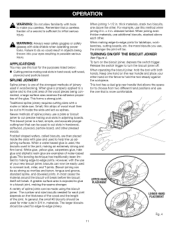
... of electric shock, fire, or serious injury. • Always wear safety glasses, Everyday eyeglasses have repaired at least 14 is in a well ventilated area, and work with a "live " and shock the operator. • Know your power tool. Following this tool. Before further use of unauthorized parts or failure to instruct others who may result in doubt, use only identical replacement parts. When using an extension cord...
... of electric shock, fire, or serious injury. • Always wear safety glasses, Everyday eyeglasses have repaired at least 14 is in a well ventilated area, and work with a "live " and shock the operator. • Know your power tool. Following this tool. Before further use of unauthorized parts or failure to instruct others who may result in doubt, use only identical replacement parts. When using an extension cord...

Operation Manual
Page 5
... surface. O _, @ @ @ ® Read The Operator's Manual Eye Protection Safety Alert No Hands Symbol No Hands Symbol No Hands Symbol No Hands Symbol Hot Surface Topoerreadtourc'se tmheanruisakl obfeifnojrueryu, suinsgerthmisuspt roredaudct.and understand Ashlwiealdys awnedarasfauflel tfyacgeogsghliesld owrhseanfeotypegrlaatsinsges thwisithprsoideuct. Failure to keep your safety. Failure to rain or use in serious personal injury. Someof the followingsymbolsmaybe usedonthis tool. roper interpretatioonfthesesymbolswillallowyouto operatethetool betterandsafer.
... surface. O _, @ @ @ ® Read The Operator's Manual Eye Protection Safety Alert No Hands Symbol No Hands Symbol No Hands Symbol No Hands Symbol Hot Surface Topoerreadtourc'se tmheanruisakl obfeifnojrueryu, suinsgerthmisuspt roredaudct.and understand Ashlwiealdys awnedarasfauflel tfyacgeogsghliesld owrhseanfeotypegrlaatsinsges thwisithprsoideuct. Failure to keep your safety. Failure to rain or use in serious personal injury. Someof the followingsymbolsmaybe usedonthis tool. roper interpretatioonfthesesymbolswillallowyouto operatethetool betterandsafer.
Operation Manual
Page 6
... performed only by a qualified service technician. When servicing, use eye protection which is marked to comply with ANSI Z87.1. We recommend Wide Vision Safety Mask for use over eyeglasses or standard safety glasses with side shields and a full face shield when needed. Before beginning power tool operation, always wear safety goggles or safety glasses with side shields. SAVE THESE INSTRUCTIONS SYMBOL SIGNAL ,_ DANGER...
... performed only by a qualified service technician. When servicing, use eye protection which is marked to comply with ANSI Z87.1. We recommend Wide Vision Safety Mask for use over eyeglasses or standard safety glasses with side shields and a full face shield when needed. Before beginning power tool operation, always wear safety goggles or safety glasses with side shields. SAVE THESE INSTRUCTIONS SYMBOL SIGNAL ,_ DANGER...

Operation Manual
Page 7
...-wire grounded power cord. It should be used. If your nearest authorized service center for repair. Only round jacketed cords listed by a qualified service technician. Before using a power tool at a considerable distance from a break in electric power tools, which eliminates the need to be grounded. _ WARNING: The double insulated system is 120 volts, 60 Hz, AC only (normal household current). A WARNING: Check extension cords before each use original factory replacement parts...
...-wire grounded power cord. It should be used. If your nearest authorized service center for repair. Only round jacketed cords listed by a qualified service technician. Before using a power tool at a considerable distance from a break in electric power tools, which eliminates the need to be grounded. _ WARNING: The double insulated system is 120 volts, 60 Hz, AC only (normal household current). A WARNING: Check extension cords before each use original factory replacement parts...

Operation Manual
Page 8
HEIGHT ADJUSTMENT KNOB HEIGHT SETTING SCALE No Load Speed 10,000/min. PRODUCT SPECIFICATIONS Fence Angle Adjustments 0-135 ° Depth of Cut 0-9/16 in . Input 120 V, 60 Hz, AC only, 6.0 Amps Net Weight 8.4 Ibs. SWITCH TRIGGER DUALGRIP HANDLE CENTERLINE/LINE OF CUTINDICATOR ADJUSTABLE FENCE NON-SKID SURFACE ANGLE SETTING SCALE DEPTH ADJUSTMENT KNOB LOCKING KNOB DUST BAG #10 BISCUIT Fig. 1 Cord Length Blade 10 ft. 4 in .
HEIGHT ADJUSTMENT KNOB HEIGHT SETTING SCALE No Load Speed 10,000/min. PRODUCT SPECIFICATIONS Fence Angle Adjustments 0-135 ° Depth of Cut 0-9/16 in . Input 120 V, 60 Hz, AC only, 6.0 Amps Net Weight 8.4 Ibs. SWITCH TRIGGER DUALGRIP HANDLE CENTERLINE/LINE OF CUTINDICATOR ADJUSTABLE FENCE NON-SKID SURFACE ANGLE SETTING SCALE DEPTH ADJUSTMENT KNOB LOCKING KNOB DUST BAG #10 BISCUIT Fig. 1 Cord Length Blade 10 ft. 4 in .

Operation Manual
Page 9
... the blade. SWITCH TRIGGER The biscuit joiner has a conveniently located ON/OFF switch trigger on the biscuit joiner can be set between 0 in. - 2 in .) This biscuit joiner is packaged with water-based woodworking glues. with positive stop settings in . vacuum can be attached to use . Before attempting to the dust port. ADJUSTABLE FENCE The biscuit joiner has an adjustable fence for operator comfort. ANGLE SETTING SCALE The adjustable fence on...
... the blade. SWITCH TRIGGER The biscuit joiner has a conveniently located ON/OFF switch trigger on the biscuit joiner can be set between 0 in. - 2 in .) This biscuit joiner is packaged with water-based woodworking glues. with positive stop settings in . vacuum can be attached to use . Before attempting to the dust port. ADJUSTABLE FENCE The biscuit joiner has an adjustable fence for operator comfort. ANGLE SETTING SCALE The adjustable fence on...
Operation Manual
Page 10
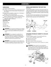
... this tool or create accessories not recommended for assistance. PACKING LIST Biscuit Joiner #10 Biscuits (20) Dust bag Carrying Case Operator's Manual INSTALLING/REMOVING See Figure 2. To install, slide the dust bag adaptor onto the dust port on the rear of your face or eyes which could result in possible serious personal injury. UNPACKING This product requires assembly. • Carefully remove the tool and any parts are...
... this tool or create accessories not recommended for assistance. PACKING LIST Biscuit Joiner #10 Biscuits (20) Dust bag Carrying Case Operator's Manual INSTALLING/REMOVING See Figure 2. To install, slide the dust bag adaptor onto the dust port on the rear of your face or eyes which could result in possible serious personal injury. UNPACKING This product requires assembly. • Carefully remove the tool and any parts are...
Operation Manual
Page 11
... and to -edge joints. The number and size biscuits needed for edge-to connect butt, miter, and T-joints. The larger biscuits should be made using the biscuit joiner. the more comfortable. TURNING ON/OFF THE BISCUIT JOINER See Figure 4. Keep one hand on the rear handle and place your other . This tool has a dual grip rear handle that allows the operator to make...
... and to -edge joints. The number and size biscuits needed for edge-to connect butt, miter, and T-joints. The larger biscuits should be made using the biscuit joiner. the more comfortable. TURNING ON/OFF THE BISCUIT JOINER See Figure 4. Keep one hand on the rear handle and place your other . This tool has a dual grip rear handle that allows the operator to make...
Operation Manual
Page 12
... adjustment knob and jam nut in the direction of the arrow. NOTE: The knob and jam nut are made by making fine adjustments with the tabs on the rear base assembly. Fit the correct size biscuit into the slot. Also periodically check the depth setting for proper alignment of wood. Adjustments are spring loaded. Make a test cut shallow biscuit slots. If the biscuit slot is used as a lock nut...
... adjustment knob and jam nut in the direction of the arrow. NOTE: The knob and jam nut are made by making fine adjustments with the tabs on the rear base assembly. Fit the correct size biscuit into the slot. Also periodically check the depth setting for proper alignment of wood. Adjustments are spring loaded. Make a test cut shallow biscuit slots. If the biscuit slot is used as a lock nut...

Operation Manual
Page 13
... blade. Each stop reached when rotating the adjustable fence from the center of the front handle for identifying these positive stop angle change. FENCE ANGLE The adjustable fence on the biscuit joiner can be positioned up to two inches from one turn . • Move the fence up to 2 in 45 ° increments. SETTING THE FENCE ANGLE See Figure 8. • Unplug the biscuit joiner. • Loosen the locking knob approximately one angle setting...
... blade. Each stop reached when rotating the adjustable fence from the center of the front handle for identifying these positive stop angle change. FENCE ANGLE The adjustable fence on the biscuit joiner can be positioned up to two inches from one turn . • Move the fence up to 2 in 45 ° increments. SETTING THE FENCE ANGLE See Figure 8. • Unplug the biscuit joiner. • Loosen the locking knob approximately one angle setting...

Operation Manual
Page 14
... the indicator marks on the fence with the centerline mark(s) on the board. • Depress the switch trigger to -edge joinery is one turn on the spring. The blade will be stronger if you are planning to make the first cut adjustment knob setting, pull back, releasing pressure on the biscuit joiner, then push it will be assembled. • Using a square, determine the location of each...
... the indicator marks on the fence with the centerline mark(s) on the board. • Depress the switch trigger to -edge joinery is one turn on the spring. The blade will be stronger if you are planning to make the first cut adjustment knob setting, pull back, releasing pressure on the biscuit joiner, then push it will be assembled. • Using a square, determine the location of each...
Operation Manual
Page 15
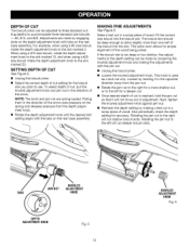
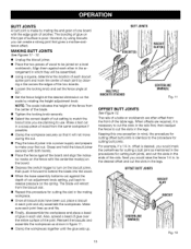
... a 1/4 in . to the desired offset and cut adjustment knob setting, pull back to use. Make a test cut in a scrap piece of wood from the center of the blade. • Tighten the locking knob securely. • Select the correct depth of cut setting to match the biscuit size you are planning to release pressure on the scale by rotating the height adjustment knob. OFFSETBUTTJOINTS BISCUIT SLOT BISCUIT CENTERLINE MARK(S) Fig...
... a 1/4 in . to the desired offset and cut adjustment knob setting, pull back to use. Make a test cut in a scrap piece of wood from the center of the blade. • Tighten the locking knob securely. • Select the correct depth of cut setting to match the biscuit size you are planning to release pressure on the scale by rotating the height adjustment knob. OFFSETBUTTJOINTS BISCUIT SLOT BISCUIT CENTERLINE MARK(S) Fig...
Operation Manual
Page 17
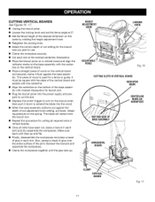
...; Loosen the locking knob and set the fence angle at 0°. • Set the fence height at the desired dimension on the scale by rotating the height adjustment knob. • Retighten the locking knob. • Select the correct depth of cut setting for the biscuit size you plan to extend the blade into the power supply and prepare to cut the slot. • Depress the switch trigger to turn on the biscuit...
...; Loosen the locking knob and set the fence angle at 0°. • Set the fence height at the desired dimension on the scale by rotating the height adjustment knob. • Retighten the locking knob. • Select the correct depth of cut setting for the biscuit size you plan to extend the blade into the power supply and prepare to cut the slot. • Depress the switch trigger to turn on the biscuit...
Operation Manual
Page 18
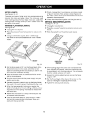
... this procedure for the biscuit size you don't want to use, and clamp the workpiece securely. • Align the indicator mark on the spring. MAKING FLAT MITER JOINTS See Figure 18. • Unplug the biscuit joiner. • Place the pieces of cut adjustment knob setting, pull back, releasing pressure on the fence with the long sides up. MAKING EDGE MITER JOINTS See Figures 19 - 21...
... this procedure for the biscuit size you don't want to use, and clamp the workpiece securely. • Align the indicator mark on the spring. MAKING FLAT MITER JOINTS See Figure 18. • Unplug the biscuit joiner. • Place the pieces of cut adjustment knob setting, pull back, releasing pressure on the fence with the long sides up. MAKING EDGE MITER JOINTS See Figures 19 - 21...

Operation Manual
Page 20
... at a Sears Service Center. Use clean cloths to be damaged by the customer. Electric tools used on a workbench. • With a screwdriver, remove the four screws and wash- Consequently, we do work with a sufficient amount of high grade lubricant for extended work on the parts list are susceptible to bearings, brushes, commutators, etc. Chemicals can damage, weaken or destroy plastic which will require replacing the blade. •...
... at a Sears Service Center. Use clean cloths to be damaged by the customer. Electric tools used on a workbench. • With a screwdriver, remove the four screws and wash- Consequently, we do work with a sufficient amount of high grade lubricant for extended work on the parts list are susceptible to bearings, brushes, commutators, etc. Chemicals can damage, weaken or destroy plastic which will require replacing the blade. •...

Operation Manual
Page 21
SCREWDRIVER NON-CUTTING TOOTHBEHIND CARBIDE-TIPPED CUTTINGTOOTH HEXKEY • Remove the outer blade washer, blade and inner blade washer. • Clean wood particles and resin from the blade washers, dust bag area, base assembly, and all surrounding parts. • Place the inner blade washer on the gear spindle. • Place the new blade onto the shoulder of the blade washer and secure with a screwdriver. • Replace the dust bag. • Placea screwdriveirnthe holeprovidedinthebearing plate. • Placeoneofthenon...
SCREWDRIVER NON-CUTTING TOOTHBEHIND CARBIDE-TIPPED CUTTINGTOOTH HEXKEY • Remove the outer blade washer, blade and inner blade washer. • Clean wood particles and resin from the blade washers, dust bag area, base assembly, and all surrounding parts. • Place the inner blade washer on the gear spindle. • Place the new blade onto the shoulder of the blade washer and secure with a screwdriver. • Replace the dust bag. • Placea screwdriveirnthe holeprovidedinthebearing plate. • Placeoneofthenon...

Operation Manual
Page 24
... and have built up on bearing plate where base slides. SOLUTION A. Make fine adjustments to see if biscuits are too deep or too shallow. See "Making Fine Adjustments." B. Compress biscuits in when cutting slots. D. Check to depth setting. Empty the dust bag often. See "Cleaning the Base Assembly and Dust Path." A. Apply a thin coat of motor when cutting slots. Blade is not functioning properly. B. See...
... and have built up on bearing plate where base slides. SOLUTION A. Make fine adjustments to see if biscuits are too deep or too shallow. See "Making Fine Adjustments." B. Compress biscuits in when cutting slots. D. Check to depth setting. Empty the dust bag often. See "Cleaning the Base Assembly and Dust Path." A. Apply a thin coat of motor when cutting slots. Blade is not functioning properly. B. See...
Operation Manual
Page 26
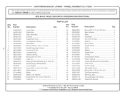
...Gear 2 C-Ring 2 Compression Spring 2 Plastic Washer 1 Height Adjustment Rod Assembly 1 Fixed Knob 1 Fence Handle 1 Adjustable Fence 1 * Screw (M4 X 18 mm Fiat Hd 2 Dust Bag Assembly 1 Warning Label 2 Carrying Case (net shown 1 Operator's Manual * Standard Hardware Item - Hd 2 31 Depth Adjustment Knob 1 32 Lock Nut (8-32 1 33 Locking Knob 1 34 Tension Spring 2 35 Screw (M4 X 8 mm 4 36 Track (L 1 37 Bearing Plate Assembly (Incl. Fil. Key 16) ...... 1 38 Bail Bearing (CW#6200RS 1 39 Lock Washer 4 40 Screw (M4 x 16 mm Pan Hd 4 41 Blade...
...Gear 2 C-Ring 2 Compression Spring 2 Plastic Washer 1 Height Adjustment Rod Assembly 1 Fixed Knob 1 Fence Handle 1 Adjustable Fence 1 * Screw (M4 X 18 mm Fiat Hd 2 Dust Bag Assembly 1 Warning Label 2 Carrying Case (net shown 1 Operator's Manual * Standard Hardware Item - Hd 2 31 Depth Adjustment Knob 1 32 Lock Nut (8-32 1 33 Locking Knob 1 34 Tension Spring 2 35 Screw (M4 X 8 mm 4 36 Track (L 1 37 Bearing Plate Assembly (Incl. Fil. Key 16) ...... 1 38 Bail Bearing (CW#6200RS 1 39 Lock Washer 4 40 Screw (M4 x 16 mm Pan Hd 4 41 Blade...


