HP Client Manager 6.1
Page 3
...side events, such as a chassis intrusion, disk drive error, battery status, thermal changes, and "walking assets" such as new or missing PCs, memory, battery, disk drives, CPUs, and monitors. Use the HP Client Manager console to remotely initialize the security chip on the client...on those client computers that contain hardware supported by HP to see where installation failed. Software installations are performed only on the memory, CPU, storage devices, and I/O devices. Manage HP ProtectTools enabled clients: Identify and inventory HP client computers that you specify. Change BIOS ...
...side events, such as a chassis intrusion, disk drive error, battery status, thermal changes, and "walking assets" such as new or missing PCs, memory, battery, disk drives, CPUs, and monitors. Use the HP Client Manager console to remotely initialize the security chip on the client...on those client computers that contain hardware supported by HP to see where installation failed. Software installations are performed only on the memory, CPU, storage devices, and I/O devices. Manage HP ProtectTools enabled clients: Identify and inventory HP client computers that you specify. Change BIOS ...
HP Client Manager 6.1
Page 8
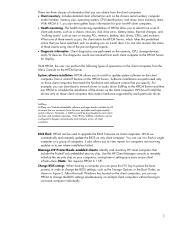
You can specify that an e-mail be sent to you to alert you to memory changes, disk drive changes, or CPU changes. For example, you to the situation. In addition to monitor the health of your predefined notification policies. The health monitoring capability of HPCM simplifies ...
You can specify that an e-mail be sent to you to alert you to memory changes, disk drive changes, or CPU changes. For example, you to the situation. In addition to monitor the health of your predefined notification policies. The health monitoring capability of HPCM simplifies ...
HP Client Manager 6.1
Page 9
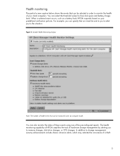
Figure 6. The partial screen capture in this screen shot). Diagnostics Diagnostics are reported in the far right column (not shown in Figure 6 shows a typical diagnostics report. Errors detected by the diagnostic software are performed on the memory, CPU, storage devices and I/O devices. Sample Diagnostics screen 9
Figure 6. The partial screen capture in this screen shot). Diagnostics Diagnostics are reported in the far right column (not shown in Figure 6 shows a typical diagnostics report. Errors detected by the diagnostic software are performed on the memory, CPU, storage devices and I/O devices. Sample Diagnostics screen 9
Testing on HP Business Desktop PCs
Page 4
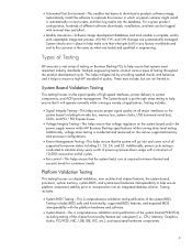
... System Board-This is comprehensive validation and qualification of the system board (PCB/PCA) including testing of the chipset functionality/feature set, subsystem (i.e., CPU, Memory, Graphics, Audio, PCI/PCIE, NIC, USB, IDE, LPC, etc.), and associated hardware components. 4 Multiple engineering teams conduct various types...it helps to ensure a high HP standard of quality. Additionally, power cycle testing is conducted and measured on Business Desktop PCs to help ensure platform component stability prior to incorporation into and come out of all major interfaces on the system board and...
... System Board-This is comprehensive validation and qualification of the system board (PCB/PCA) including testing of the chipset functionality/feature set, subsystem (i.e., CPU, Memory, Graphics, Audio, PCI/PCIE, NIC, USB, IDE, LPC, etc.), and associated hardware components. 4 Multiple engineering teams conduct various types...it helps to ensure a high HP standard of quality. Additionally, power cycle testing is conducted and measured on Business Desktop PCs to help ensure platform component stability prior to incorporation into and come out of all major interfaces on the system board and...
HP Compaq dc5100 Business PC Series Illustrated Parts Map, Microtower, 2nd Edition
Page 2
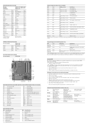
... Aux power LED E49 Password jumper J20 PCI slot 1 J21 PCI slot 2 J31 PCI Express x1 P1 Main power (20 pin) P3 CPU regulator power (4 pin) P5 Front panel P6 Internal chassis speaker P7 CD audio in P8 Chassis fan P10 Diskette drive P11 Aux audio in...XMM3 XMM4 XU1 Primary IDE Front audio/USB Front USB header Flying Serial Port Primary Serial ATA (SATA) connector Second Serial ATA (SATA) connector CPU fan CMOS button Battery Memory socket Memory socket Memory socket Memory socket Processor socket System Hardware Interrupts IRQ System Function 0 Timer Interrupt 1 Keyboard ...
... Aux power LED E49 Password jumper J20 PCI slot 1 J21 PCI slot 2 J31 PCI Express x1 P1 Main power (20 pin) P3 CPU regulator power (4 pin) P5 Front panel P6 Internal chassis speaker P7 CD audio in P8 Chassis fan P10 Diskette drive P11 Aux audio in...XMM3 XMM4 XU1 Primary IDE Front audio/USB Front USB header Flying Serial Port Primary Serial ATA (SATA) connector Second Serial ATA (SATA) connector CPU fan CMOS button Battery Memory socket Memory socket Memory socket Memory socket Processor socket System Hardware Interrupts IRQ System Function 0 Timer Interrupt 1 Keyboard ...
Troubleshooting Guide
Page 68
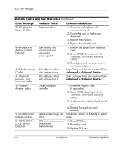
.... 2. Ensure that none of ROMPaq to parallel port X. 1. Remove any parallel port expansion cards. 2. image. 511-CPU, CPUA, or CPUB Fan not Detected CPU fan is attached and turned on. 4. Replace the system board. 404-Parallel Port Address Conflict Detected Both external and internal ... card (if possible). 510-Splash Screen Image Corrupted Splash Screen image has Install latest version of the keys are assigned to restore errors. Replace CPU fan. Clear CMOS. (See Appendix B, "Password Security and Resetting CMOS.") 3. Enter Computer Setup and reset the IRQ in Advanced > Onboard ...
.... 2. Ensure that none of ROMPaq to parallel port X. 1. Remove any parallel port expansion cards. 2. image. 511-CPU, CPUA, or CPUB Fan not Detected CPU fan is attached and turned on. 4. Replace the system board. 404-Parallel Port Address Conflict Detected Both external and internal ... card (if possible). 510-Splash Screen Image Corrupted Splash Screen image has Install latest version of the keys are assigned to restore errors. Replace CPU fan. Clear CMOS. (See Appendix B, "Password Security and Resetting CMOS.") 3. Enter Computer Setup and reset the IRQ in Advanced > Onboard ...
Troubleshooting Guide
Page 69
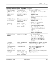
...Setup. 2. Clear CMOS. (See Appendix B, "Password Security and Resetting CMOS.") 610-External Storage Device Failure External tape drive not connected. Reseat CPU or chassis fan. 2. Run Computer Setup and check the configuration in drive type. 1. Check and/or replace cables. 3. Clear CMOS. ...Run Computer Setup. 2. Replace chassis, rear chassis, or front chassis fan. 514-CPU or Chassis Fan not Detected CPU or chassis fan is not working properly and will be disabled. Replace CPU or chassis fan. 601-Diskette Controller Error Diskette controller circuitry or floppy drive circuitry...
...Setup. 2. Clear CMOS. (See Appendix B, "Password Security and Resetting CMOS.") 610-External Storage Device Failure External tape drive not connected. Reseat CPU or chassis fan. 2. Run Computer Setup and check the configuration in drive type. 1. Check and/or replace cables. 3. Clear CMOS. ...Run Computer Setup. 2. Replace chassis, rear chassis, or front chassis fan. 514-CPU or Chassis Fan not Detected CPU or chassis fan is not working properly and will be disabled. Replace CPU or chassis fan. 601-Diskette Controller Error Diskette controller circuitry or floppy drive circuitry...

Troubleshooting Guide
Page 75
... the processor fan. Ensure that none of the keys are depressed. 4. If the fan is plugged in VSFF chassis. 1. System will not boot without fan CPU fan not installed or disconnected in and seated properly, but is fully/properly seated or installed. 2. Check connector for bent or missing pins. 3. Run Computer...
... the processor fan. Ensure that none of the keys are depressed. 4. If the fan is plugged in VSFF chassis. 1. System will not boot without fan CPU fan not installed or disconnected in and seated properly, but is fully/properly seated or installed. 2. Check connector for bent or missing pins. 3. Run Computer...

HP Disk Sanitizer, External Edition
Page 5
... all other drives except the drive to be Drive 0x81. USB drives are typically less than the hard drive will ever be disconnected from the PC before running HP Disk Sanitizer, External Edition. However, if a user boots from a CD, all cases, a small section of non-personal metadata used in order... of data. If you boot the Disk Sanitizer utility from a USB drive, the USB drive will be erased. Even in the future, the CPU will be able to process and execute the application faster than 5GB. If you run this application is written to keep in RAID mode...
... all other drives except the drive to be Drive 0x81. USB drives are typically less than the hard drive will ever be disconnected from the PC before running HP Disk Sanitizer, External Edition. However, if a user boots from a CD, all cases, a small section of non-personal metadata used in order... of data. If you boot the Disk Sanitizer utility from a USB drive, the USB drive will be erased. Even in the future, the CPU will be able to process and execute the application faster than 5GB. If you run this application is written to keep in RAID mode...

HP Compaq Business Desktop dc5100 Service Reference Guide, 2nd Edition
Page 76
...the computer, it can damage the computer. 5.5.5 Hard Drives Handle hard drives as monitors or speakers. 5-8 376220-001 Service Reference Guide, dc5100 Improper cable placement can damage the unit. This applies to prevent damage. 5.5.4 Cables and Connectors Most cables used during the reassembly process, it...drives in their protective packaging until they cannot be kept with care to liquids, temperature extremes, or products that cables are placed in the CPU. ■ Avoid dropping drives from any height onto any surface. ■ If you are routed in such a way that they ...
...the computer, it can damage the computer. 5.5.5 Hard Drives Handle hard drives as monitors or speakers. 5-8 376220-001 Service Reference Guide, dc5100 Improper cable placement can damage the unit. This applies to prevent damage. 5.5.4 Cables and Connectors Most cables used during the reassembly process, it...drives in their protective packaging until they cannot be kept with care to liquids, temperature extremes, or products that cables are placed in the CPU. ■ Avoid dropping drives from any height onto any surface. ■ If you are routed in such a way that they ...
HP Compaq Business Desktop dc5100 Service Reference Guide, 2nd Edition
Page 127
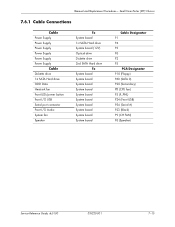
... System board System board System board System board Cable Designator P1 P4 P3 P6 P2 P5 PCA Designator P10 (Floppy) P60 (SATA 0) P20 (Secondary) P8 (CPU fan) P5 (F_PNL) P24 (Front USB) P54 (Serial A) P23 (Black) P9 (CH FAN) P6 (Speaker) Service Reference Guide...
... System board System board System board System board Cable Designator P1 P4 P3 P6 P2 P5 PCA Designator P10 (Floppy) P60 (SATA 0) P20 (Secondary) P8 (CPU fan) P5 (F_PNL) P24 (Front USB) P54 (Serial A) P23 (Black) P9 (CH FAN) P6 (Speaker) Service Reference Guide...

HP Compaq Business Desktop dc5100 Service Reference Guide, 2nd Edition
Page 169
... MicroFit Power Connector 24 13 12 Pin Signal 1 +5 Vaux 2 GND 3 +5 V 4 +5 V 5 PS_ON 6 GND Pin Signal 7 PWRGD 8 +3.3 V 9 +3.3 V 10 Tach 11 GND 12 Fan-CMD 4-Pin Power (for CPU) Connector and Icon 1 Pin Signal 13 +12 V 14 +5 V Sense 15 GND 16 +5 V 17 +5 V 18 +3.3 V Pin Signal 1 GND 2 GND 3 +12...
... MicroFit Power Connector 24 13 12 Pin Signal 1 +5 Vaux 2 GND 3 +5 V 4 +5 V 5 PS_ON 6 GND Pin Signal 7 PWRGD 8 +3.3 V 9 +3.3 V 10 Tach 11 GND 12 Fan-CMD 4-Pin Power (for CPU) Connector and Icon 1 Pin Signal 13 +12 V 14 +5 V Sense 15 GND 16 +5 V 17 +5 V 18 +3.3 V Pin Signal 1 GND 2 GND 3 +12...

HP Compaq Business Desktop dc5100 Service Reference Guide, 2nd Edition
Page 170
S2 A+ S6 B+ P1 V 3.3 P5 Ground P9 V 5 P13 V 12 P2 V 3.3 P6 Ground P10 Ground P14 V 12 *S = Data, P = Power Pin Signal S3 AS7 Ground P3 V 3.3 P7 V 5 P11 Reserved P15 V 12 Pin Signal S4 Ground P4 Ground P8 V 5 P12 Ground A-8 376220-001 Service Reference Guide, dc5100 Connector Pin Assignments 6-Pin Power Connector and Icon 4 6 Pin Signal 1 GND 2 GND 3 GND 4 12 V CPU 5 12 V CPU 6 +12 V SATA Data and Power Drive Connector Pin Signal Pin Signal S1 Ground S5 B-
S2 A+ S6 B+ P1 V 3.3 P5 Ground P9 V 5 P13 V 12 P2 V 3.3 P6 Ground P10 Ground P14 V 12 *S = Data, P = Power Pin Signal S3 AS7 Ground P3 V 3.3 P7 V 5 P11 Reserved P15 V 12 Pin Signal S4 Ground P4 Ground P8 V 5 P12 Ground A-8 376220-001 Service Reference Guide, dc5100 Connector Pin Assignments 6-Pin Power Connector and Icon 4 6 Pin Signal 1 GND 2 GND 3 GND 4 12 V CPU 5 12 V CPU 6 +12 V SATA Data and Power Drive Connector Pin Signal Pin Signal S1 Ground S5 B-

HP Compaq Business Desktop dc5100 Service Reference Guide, 2nd Edition
Page 177
...fan. Replace chassis, rear chassis, or front chassis fan. Replace CPU or chassis fan. Clear CMOS. Reseat the fan. Run Computer Setup (F10 Setup). Replace the system board. Service Reference Guide, dc5100 376220-001 C-3 POST Error Messages Screen Message 301-Keyboard Error Probable ...Cause Keyboard failure. 303-Keyboard Controller Error 304-Keyboard or System Unit Error I/O board keyboard controller. CPU fan is not connected or may have ...
...fan. Replace chassis, rear chassis, or front chassis fan. Replace CPU or chassis fan. Clear CMOS. Reseat the fan. Run Computer Setup (F10 Setup). Replace the system board. Service Reference Guide, dc5100 376220-001 C-3 POST Error Messages Screen Message 301-Keyboard Error Probable ...Cause Keyboard failure. 303-Keyboard Controller Error 304-Keyboard or System Unit Error I/O board keyboard controller. CPU fan is not connected or may have ...

HP Compaq Business Desktop dc5100 Service Reference Guide, 2nd Edition
Page 221
...U29 U30 U31 U32 Component (Continued) MultiBay header SCSI LED connector PCI extender slot (female) Blade PC graphics connector (outboard) Blade PC graphics connector (inboard) Serial port header First serial port Flying serial port Double stack serial port, ...SATA) connector Fourth Serial ATA (SATA) connector VSFF expansion connector Graphics option connector Primary (CPU) fan header for fansink Secondary CPU fan header for fansink Security board connector, system board Secondary speaker header Hood lock header ... Second serial port transceiver Service Reference Guide, dc5100 376220-001 E-3
...U29 U30 U31 U32 Component (Continued) MultiBay header SCSI LED connector PCI extender slot (female) Blade PC graphics connector (outboard) Blade PC graphics connector (inboard) Serial port header First serial port Flying serial port Double stack serial port, ...SATA) connector Fourth Serial ATA (SATA) connector VSFF expansion connector Graphics option connector Primary (CPU) fan header for fansink Secondary CPU fan header for fansink Security board connector, system board Secondary speaker header Hood lock header ... Second serial port transceiver Service Reference Guide, dc5100 376220-001 E-3


