User Guide
Page 3
.../TWN rear panel...8 UPS R1500 G2 INTL rear panel ...9 Installation ...11 Precautions ...11 Preparing to install the hardware ...11 Tools required...11 Selecting a site ...11 Readying the equipment ...12 Installing the mounting rails ...12 Installing the UPS ...16 Connecting the batteries ...17 Attaching the UPS front......21 Connecting devices to the UPS ...21 Powering up the UPS ...22 Charging the UPS batteries ...22 UPS operations...23 Modes of operation...23 Standby mode ...23 Operate mode ...23 Battery mode ...24 Initiating a self-test ...24 Silencing an audible alarm ...24 Powering down the...
.../TWN rear panel...8 UPS R1500 G2 INTL rear panel ...9 Installation ...11 Precautions ...11 Preparing to install the hardware ...11 Tools required...11 Selecting a site ...11 Readying the equipment ...12 Installing the mounting rails ...12 Installing the UPS ...16 Connecting the batteries ...17 Attaching the UPS front......21 Connecting devices to the UPS ...21 Powering up the UPS ...22 Charging the UPS batteries ...22 UPS operations...23 Modes of operation...23 Standby mode ...23 Operate mode ...23 Battery mode ...24 Initiating a self-test ...24 Silencing an audible alarm ...24 Powering down the...

User Guide
Page 4
......36 Power protection specifications...37 Voltage specifications ...37 Output tolerance specifications ...37 Output feature specifications ...37 Battery specifications ...37 Battery runtime ...38 Environmental specifications ...38 Serial communications port pin assignment 38 Spares...40 Ordering spares...40 UPS ...information...41 Warranty information...42 Limited warranty ...42 $250,000 Computer Load Protection Guarantee 42 Pre-Failure Battery Warranty...42 Recommended duration of use...43 Regulatory compliance notices ...44 Regulatory compliance identification numbers 44 Federal ...
......36 Power protection specifications...37 Voltage specifications ...37 Output tolerance specifications ...37 Output feature specifications ...37 Battery specifications ...37 Battery runtime ...38 Environmental specifications ...38 Serial communications port pin assignment 38 Spares...40 Ordering spares...40 UPS ...information...41 Warranty information...42 Limited warranty ...42 $250,000 Computer Load Protection Guarantee 42 Pre-Failure Battery Warranty...42 Recommended duration of use...43 Regulatory compliance notices ...44 Regulatory compliance identification numbers 44 Federal ...

User Guide
Page 5
Disposal of waste equipment by users in private households in the European Union 46 Japanese notice ...47 BSMI notice ...48 Korean notice ...48 Battery replacement notice ...48 Power cord statement for Japan ...49 Electrostatic discharge ...50 Preventing electrostatic discharge ...50 Grounding methods to prevent electrostatic discharge 50 Acronyms and abbreviations...51 Index...52
Disposal of waste equipment by users in private households in the European Union 46 Japanese notice ...47 BSMI notice ...48 Korean notice ...48 Battery replacement notice ...48 Power cord statement for Japan ...49 Electrostatic discharge ...50 Preventing electrostatic discharge ...50 Grounding methods to prevent electrostatic discharge 50 Acronyms and abbreviations...51 Index...52

User Guide
Page 6
UPS front panel Item 1 2 Description Battery compartment Control buttons and LED display Component identification 6 To benefit from the latest product enhancements, update to 1440 VA/1000 W (NA/TWN), 1200 VA/1000 W (JPN) or 1500 VA/1000 W (INTL). NOTE: To download the latest versions of UPS firmware and software. Component identification UPS R1500 G2 overview The HP UPS R1500 G2 features a 1U rack-mount design and offers power protection for loads up to the latest versions of UPS firmware and software, see the HP website (http://www.hp.com/go/rackandpower).
UPS front panel Item 1 2 Description Battery compartment Control buttons and LED display Component identification 6 To benefit from the latest product enhancements, update to 1440 VA/1000 W (NA/TWN), 1200 VA/1000 W (JPN) or 1500 VA/1000 W (INTL). NOTE: To download the latest versions of UPS firmware and software. Component identification UPS R1500 G2 overview The HP UPS R1500 G2 features a 1U rack-mount design and offers power protection for loads up to the latest versions of UPS firmware and software, see the HP website (http://www.hp.com/go/rackandpower).

User Guide
Page 8
UPS front panel LED indicators Item 1 2 3 4 5 6 LED description Load Segment 2 Load Segment 1 General Alarm On Battery Overload Power On For more information, see "LED and audible alarm troubleshooting (on page 33)." UPS R1500 G2 NA/JPN/TWN rear panel Component identification 8
UPS front panel LED indicators Item 1 2 3 4 5 6 LED description Load Segment 2 Load Segment 1 General Alarm On Battery Overload Power On For more information, see "LED and audible alarm troubleshooting (on page 33)." UPS R1500 G2 NA/JPN/TWN rear panel Component identification 8

User Guide
Page 9
... protection) Load segment 2 (two NEMA 5-15 output receptacles for surge and battery backup protection) Voltage configuration DIP switches Serial communications port USB communications port Input power cord with NEMA 5-15 plug (BSMI approved for TWN) UPS R1500 G2 INTL rear panel Item 1 2 3 4 5 6 7 8 Description Input circuit breaker Network Transient Protector IN jack Network...
... protection) Load segment 2 (two NEMA 5-15 output receptacles for surge and battery backup protection) Voltage configuration DIP switches Serial communications port USB communications port Input power cord with NEMA 5-15 plug (BSMI approved for TWN) UPS R1500 G2 INTL rear panel Item 1 2 3 4 5 6 7 8 Description Input circuit breaker Network Transient Protector IN jack Network...
User Guide
Page 11
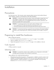
... following factors: • Elevated operating ambient temperature-If the equipment is required. The installation of options and routine maintenance and service of the UPS and batteries. Preparing to install the hardware Before installing the hardware: 1. When fully assembled, the UPS weighs 23 kg (50.5 lb). WARNING: To prevent personal injury, prepare...
... following factors: • Elevated operating ambient temperature-If the equipment is required. The installation of options and routine maintenance and service of the UPS and batteries. Preparing to install the hardware Before installing the hardware: 1. When fully assembled, the UPS weighs 23 kg (50.5 lb). WARNING: To prevent personal injury, prepare...

User Guide
Page 12
... connections to the shipping carton. Readying the equipment 1. Unpack the equipment near the rack where the unit will be maintained. Check the battery recharge date specified on the label that is affixed to the branch circuit, such as stated in multiple-rack installations. • Only ... strips. • Electrical requirements-All models require a dedicated (unshared) branch circuit, suitably rated for the specific UPS as the use the battery if the recharge date has passed. CAUTION: Always plan the rack installation so that overloading of the circuits might have on page 36)" ....
... connections to the shipping carton. Readying the equipment 1. Unpack the equipment near the rack where the unit will be maintained. Check the battery recharge date specified on the label that is affixed to the branch circuit, such as stated in multiple-rack installations. • Only ... strips. • Electrical requirements-All models require a dedicated (unshared) branch circuit, suitably rated for the specific UPS as the use the battery if the recharge date has passed. CAUTION: Always plan the rack installation so that overloading of the circuits might have on page 36)" ....

User Guide
Page 17
... mounting rails and then attach the brackets to temperatures higher than 40°C (104°F). Installation 17 Connecting the batteries WARNING: The unit contains sealed lead-acid battery modules. To prevent fire or chemical burns: • Do not attempt to recharge batteries after removal from the unit. • Do not disassemble, crush, or puncture the...
... mounting rails and then attach the brackets to temperatures higher than 40°C (104°F). Installation 17 Connecting the batteries WARNING: The unit contains sealed lead-acid battery modules. To prevent fire or chemical burns: • Do not attempt to recharge batteries after removal from the unit. • Do not disassemble, crush, or puncture the...

User Guide
Page 18
Attaching the UPS front bezel Installation 18 Connect the battery lead to the battery terminal.
Attaching the UPS front bezel Installation 18 Connect the battery lead to the battery terminal.

User Guide
Page 21
...CAUTION: Do not plug laser printers into a grounded (earthed) electrical outlet that is installed near the equipment and is plugged in, the batteries begin to the IEC-320-C14 input power connector on page 25)" . Connecting devices to the equipment: • Plug the input line... cords. 1. To protect equipment against surges over a network data line: 1. Connect the equipment to the output receptacles designated for surge and battery backup is not available until the unit is an important safety feature. • Do not use the Network Transient Protector with a standard telephone...
...CAUTION: Do not plug laser printers into a grounded (earthed) electrical outlet that is installed near the equipment and is plugged in, the batteries begin to the IEC-320-C14 input power connector on page 25)" . Connecting devices to the equipment: • Plug the input line... cords. 1. To protect equipment against surges over a network data line: 1. Connect the equipment to the output receptacles designated for surge and battery backup is not available until the unit is an important safety feature. • Do not use the Network Transient Protector with a standard telephone...

User Guide
Page 22
... the rear panel of the UPS (NA/JPN/TWN model). -or- • Connect devices to the output receptacles on page 23), allow the batteries to charge before supplying backup power to devices. The Power On, Load 1 and Load 2 LEDs illuminate, indicating that power is listed in Standby ...model). Before connecting devices, verify that the UPS will not overload by the selected output voltage to determine the VA. IMPORTANT: Charge the batteries for at the UPS output receptacles. After verifying that the ratings of their capacity within 24 hours Installation 22 If the equipment rating is ...
... the rear panel of the UPS (NA/JPN/TWN model). -or- • Connect devices to the output receptacles on page 23), allow the batteries to charge before supplying backup power to devices. The Power On, Load 1 and Load 2 LEDs illuminate, indicating that power is listed in Standby ...model). Before connecting devices, verify that the UPS will not overload by the selected output voltage to determine the VA. IMPORTANT: Charge the batteries for at the UPS output receptacles. After verifying that the ratings of their capacity within 24 hours Installation 22 If the equipment rating is ...

User Guide
Page 23
...acknowledges compliance with a short beep. Operate mode In Operate mode: • Power is available at the UPS receptacles. • The UPS charges the batteries as necessary. To place the UPS in Operate mode (the Power On LED ("UPS front panel LED indicators" on page 8) is illuminated). IMPORTANT: While... until an alternate mode is selected or until utility power is removed. The UPS remains in Standby mode, the UPS maintains the charge on the batteries, but no utility power is available. The Power On, Load 1 and Load 2 LEDs ("UPS front panel LED indicators" on page 8) illuminate, ...
...acknowledges compliance with a short beep. Operate mode In Operate mode: • Power is available at the UPS receptacles. • The UPS charges the batteries as necessary. To place the UPS in Operate mode (the Power On LED ("UPS front panel LED indicators" on page 8) is illuminated). IMPORTANT: While... until an alternate mode is selected or until utility power is removed. The UPS remains in Standby mode, the UPS maintains the charge on the batteries, but no utility power is available. The Power On, Load 1 and Load 2 LEDs ("UPS front panel LED indicators" on page 8) illuminate, ...

User Guide
Page 24
... 7) for three seconds. To power up the UPS without being connected to utility power. Because a portion of the self-test requires battery power, the self-test cannot be initiated if the batteries are less than 90 percent charged. IMPORTANT: • Although the audible alarm silences, the condition that caused the alarm to...
... 7) for three seconds. To power up the UPS without being connected to utility power. Because a portion of the self-test requires battery power, the self-test cannot be initiated if the batteries are less than 90 percent charged. IMPORTANT: • Although the audible alarm silences, the condition that caused the alarm to...

User Guide
Page 27
... the environment is installed, the serial and USB communications ports are automatically disabled. Important battery safety information WARNING: The unit contains sealed lead-acid battery modules. Battery care and storage guidelines CAUTION: Because of the short shelf life of batteries. NOTE: Replace all battery modules at the same time. See "Selecting the UPS voltage configuration (on top...
... the environment is installed, the serial and USB communications ports are automatically disabled. Important battery safety information WARNING: The unit contains sealed lead-acid battery modules. Battery care and storage guidelines CAUTION: Because of the short shelf life of batteries. NOTE: Replace all battery modules at the same time. See "Selecting the UPS voltage configuration (on top...

User Guide
Page 28
.... Remove the UPS front bezel ("Removing the UPS front bezel" on page 24)." 2. Disconnect the battery leads. 4. UPS battery replacement procedure This component is hot-swappable and can be replaced without powering down the UPS. 1. (optional) To replace the component with the UPS powered ... the UPS (on page 26). 3. • Maintain the ambient temperature at 25°C (77°F). • If storing a UPS for an extended period, recharge the batteries ("Charging the UPS batteries" on page 22) every 6 months, and then update the...
.... Remove the UPS front bezel ("Removing the UPS front bezel" on page 24)." 2. Disconnect the battery leads. 4. UPS battery replacement procedure This component is hot-swappable and can be replaced without powering down the UPS. 1. (optional) To replace the component with the UPS powered ... the UPS (on page 26). 3. • Maintain the ambient temperature at 25°C (77°F). • If storing a UPS for an extended period, recharge the batteries ("Charging the UPS batteries" on page 22) every 6 months, and then update the...

User Guide
Page 29
...capacity within 4 hours • 100% of their capacity within 24 hours Testing the new battery module After installing the new battery module, press the Test/Alarm Reset button. The batteries charge to devices. If the installation has been successful, the UPS enters Operate mode. ...UPS To remove the UPS: 1. The batteries charge to devices. Power down all attached load devices. IMPORTANT: Do not pull the battery leads when removing or installing the batteries. If this occurs, repeat the procedures in "Replacing the batteries (on page 33)." For information on ...
...capacity within 4 hours • 100% of their capacity within 24 hours Testing the new battery module After installing the new battery module, press the Test/Alarm Reset button. The batteries charge to devices. If the installation has been successful, the UPS enters Operate mode. ...UPS To remove the UPS: 1. The batteries charge to devices. Power down all attached load devices. IMPORTANT: Do not pull the battery leads when removing or installing the batteries. If this occurs, repeat the procedures in "Replacing the batteries (on page 33)." For information on ...

User Guide
Page 30
... 1 Maintenance 30 Disconnect the communications cable. 5. Remove the UPS front bezel ("Removing the UPS front bezel" on page 24). 3. Remove the UPS battery bracket. 8. Updating the UPS firmware To update the UPS firmware, see the HP website (http://www.hp.com/go/rackandpower). In the tree displayed... download might be downloaded from the rack. Connect the USB to serial converter to serial converter (part number 304098-001). Remove the UPS battery modules. 9. Remove the UPS from the USB-Drivers website (http://www.usb-drivers.com/drivers/123/123294.htm). Depending on your USB ...
... 1 Maintenance 30 Disconnect the communications cable. 5. Remove the UPS front bezel ("Removing the UPS front bezel" on page 24). 3. Remove the UPS battery bracket. 8. Updating the UPS firmware To update the UPS firmware, see the HP website (http://www.hp.com/go/rackandpower). In the tree displayed... download might be downloaded from the rack. Connect the USB to serial converter to serial converter (part number 304098-001). Remove the UPS battery modules. 9. Remove the UPS from the USB-Drivers website (http://www.usb-drivers.com/drivers/123/123294.htm). Depending on your USB ...

User Guide
Page 32
... severely damage your eyes and skin. 2. Properly dispose of ignition. 3. WARNING: Do not allow discharge of unneutralized acid to 1 gallon of 1 lb baking soda to reach the sewer. Neutralize spilled battery acid with the special solutions contained in a drum or other suitable container. 6. Be sure the mixture is neutral, then collect the residue...
... severely damage your eyes and skin. 2. Properly dispose of ignition. 3. WARNING: Do not allow discharge of unneutralized acid to 1 gallon of 1 lb baking soda to reach the sewer. Neutralize spilled battery acid with the special solutions contained in a drum or other suitable container. 6. Be sure the mixture is neutral, then collect the residue...

User Guide
Page 33
... utility power) Online-UPS power capacity exceeded Overload timeout On battery-Input voltage is out of range On battery-No utility power On battery-Battery voltage condition On battery- Overload condition On On On On Off On On Flashing Off On Off On Off Flashing Off Off Off Off On On Off ... On-Continuous Yes On Off On-1 second No beep Troubleshooting 33 Troubleshooting LED and audible alarm troubleshooting Condition Power On LED (green) On Battery LED (yellow) UPS operating from utility Buck mode (high input voltage) Boost mode (low input voltage) Over temperature condition...
... utility power) Online-UPS power capacity exceeded Overload timeout On battery-Input voltage is out of range On battery-No utility power On battery-Battery voltage condition On battery- Overload condition On On On On Off On On Flashing Off On Off On Off Flashing Off Off Off Off On On Off ... On-Continuous Yes On Off On-1 second No beep Troubleshooting 33 Troubleshooting LED and audible alarm troubleshooting Condition Power On LED (green) On Battery LED (yellow) UPS operating from utility Buck mode (high input voltage) Boost mode (low input voltage) Over temperature condition...
