User Guide
Page 3
.../TWN rear panel...8 UPS R1500 G2 INTL rear panel ...9 Installation ...11 Precautions ...11 Preparing to install the hardware ...11 Tools required...11 Selecting a site ...11 Readying the equipment ...12 Installing the mounting rails ...12 Installing the UPS ...16 Connecting the batteries ...17 Attaching the UPS front......21 Connecting devices to the UPS ...21 Powering up the UPS ...22 Charging the UPS batteries ...22 UPS operations...23 Modes of operation...23 Standby mode ...23 Operate mode ...23 Battery mode ...24 Initiating a self-test ...24 Silencing an audible alarm ...24 Powering down the...
.../TWN rear panel...8 UPS R1500 G2 INTL rear panel ...9 Installation ...11 Precautions ...11 Preparing to install the hardware ...11 Tools required...11 Selecting a site ...11 Readying the equipment ...12 Installing the mounting rails ...12 Installing the UPS ...16 Connecting the batteries ...17 Attaching the UPS front......21 Connecting devices to the UPS ...21 Powering up the UPS ...22 Charging the UPS batteries ...22 UPS operations...23 Modes of operation...23 Standby mode ...23 Operate mode ...23 Battery mode ...24 Initiating a self-test ...24 Silencing an audible alarm ...24 Powering down the...

User Guide
Page 4
......36 Power protection specifications...37 Voltage specifications ...37 Output tolerance specifications ...37 Output feature specifications ...37 Battery specifications ...37 Battery runtime ...38 Environmental specifications ...38 Serial communications port pin assignment 38 Spares...40 Ordering spares...40 UPS ...information...41 Warranty information...42 Limited warranty ...42 $250,000 Computer Load Protection Guarantee 42 Pre-Failure Battery Warranty...42 Recommended duration of use...43 Regulatory compliance notices ...44 Regulatory compliance identification numbers 44 Federal ...
......36 Power protection specifications...37 Voltage specifications ...37 Output tolerance specifications ...37 Output feature specifications ...37 Battery specifications ...37 Battery runtime ...38 Environmental specifications ...38 Serial communications port pin assignment 38 Spares...40 Ordering spares...40 UPS ...information...41 Warranty information...42 Limited warranty ...42 $250,000 Computer Load Protection Guarantee 42 Pre-Failure Battery Warranty...42 Recommended duration of use...43 Regulatory compliance notices ...44 Regulatory compliance identification numbers 44 Federal ...

User Guide
Page 5
Disposal of waste equipment by users in private households in the European Union 46 Japanese notice ...47 BSMI notice ...48 Korean notice ...48 Battery replacement notice ...48 Power cord statement for Japan ...49 Electrostatic discharge ...50 Preventing electrostatic discharge ...50 Grounding methods to prevent electrostatic discharge 50 Acronyms and abbreviations...51 Index...52
Disposal of waste equipment by users in private households in the European Union 46 Japanese notice ...47 BSMI notice ...48 Korean notice ...48 Battery replacement notice ...48 Power cord statement for Japan ...49 Electrostatic discharge ...50 Preventing electrostatic discharge ...50 Grounding methods to prevent electrostatic discharge 50 Acronyms and abbreviations...51 Index...52

User Guide
Page 6
Component identification UPS R1500 G2 overview The HP UPS R1500 G2 features a 1U rack-mount design and offers power protection for loads up to the latest versions of UPS firmware and software, see the HP website (http://www.hp.com/go/rackandpower). NOTE: To download the latest versions of UPS firmware and software. To benefit from the latest product enhancements, update to 1440 VA/1000 W (NA/TWN), 1200 VA/1000 W (JPN) or 1500 VA/1000 W (INTL). UPS front panel Item 1 2 Description Battery compartment Control buttons and LED display Component identification 6
Component identification UPS R1500 G2 overview The HP UPS R1500 G2 features a 1U rack-mount design and offers power protection for loads up to the latest versions of UPS firmware and software, see the HP website (http://www.hp.com/go/rackandpower). NOTE: To download the latest versions of UPS firmware and software. To benefit from the latest product enhancements, update to 1440 VA/1000 W (NA/TWN), 1200 VA/1000 W (JPN) or 1500 VA/1000 W (INTL). UPS front panel Item 1 2 Description Battery compartment Control buttons and LED display Component identification 6

User Guide
Page 8
UPS R1500 G2 NA/JPN/TWN rear panel Component identification 8 UPS front panel LED indicators Item 1 2 3 4 5 6 LED description Load Segment 2 Load Segment 1 General Alarm On Battery Overload Power On For more information, see "LED and audible alarm troubleshooting (on page 33)."
UPS R1500 G2 NA/JPN/TWN rear panel Component identification 8 UPS front panel LED indicators Item 1 2 3 4 5 6 LED description Load Segment 2 Load Segment 1 General Alarm On Battery Overload Power On For more information, see "LED and audible alarm troubleshooting (on page 33)."

User Guide
Page 9
... protection) Load segment 2 (two NEMA 5-15 output receptacles for surge and battery backup protection) Voltage configuration DIP switches Serial communications port USB communications port Input power cord with NEMA 5-15 plug (BSMI approved for TWN) UPS R1500 G2 INTL rear panel Item 1 2 3 4 5 6 7 8 Description Input circuit breaker Network Transient Protector IN jack Network...
... protection) Load segment 2 (two NEMA 5-15 output receptacles for surge and battery backup protection) Voltage configuration DIP switches Serial communications port USB communications port Input power cord with NEMA 5-15 plug (BSMI approved for TWN) UPS R1500 G2 INTL rear panel Item 1 2 3 4 5 6 7 8 Description Input circuit breaker Network Transient Protector IN jack Network...
User Guide
Page 11
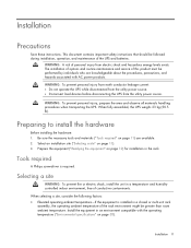
... power products. When selecting a site, consider the following factors: • Elevated operating ambient temperature-If the equipment is required. WARNING: A risk of the UPS and batteries. Tools required A Philips screwdriver is installed in the rack. and humiditycontrolled indoor environment, free of this product must be performed by individuals who are available...
... power products. When selecting a site, consider the following factors: • Elevated operating ambient temperature-If the equipment is required. WARNING: A risk of the UPS and batteries. Tools required A Philips screwdriver is installed in the rack. and humiditycontrolled indoor environment, free of this product must be performed by individuals who are available...

User Guide
Page 12
Check the battery recharge date specified on the label that is on the bottom of the rack. Install ...-rack installation. • The racks are coupled together in "Input specifications ("UPS input specifications" on the battery recharge date label has passed without the battery being recharged, contact an HP authorized service representative for the specific UPS as the use the... battery if the recharge date has passed. Unpack the equipment near the rack where the unit will be maintained....
Check the battery recharge date specified on the label that is on the bottom of the rack. Install ...-rack installation. • The racks are coupled together in "Input specifications ("UPS input specifications" on the battery recharge date label has passed without the battery being recharged, contact an HP authorized service representative for the specific UPS as the use the... battery if the recharge date has passed. Unpack the equipment near the rack where the unit will be maintained....

User Guide
Page 17
... sure that the unit is normal and does not damage the unit or present any safety concern. Connecting the batteries WARNING: The unit contains sealed lead-acid battery modules. To prevent fire or chemical burns: • Do not attempt to recharge batteries after removal from the unit. • Do not disassemble, crush, or puncture the...
... sure that the unit is normal and does not damage the unit or present any safety concern. Connecting the batteries WARNING: The unit contains sealed lead-acid battery modules. To prevent fire or chemical burns: • Do not attempt to recharge batteries after removal from the unit. • Do not disassemble, crush, or puncture the...

User Guide
Page 18
Connect the battery lead to the battery terminal. Attaching the UPS front bezel Installation 18
Connect the battery lead to the battery terminal. Attaching the UPS front bezel Installation 18

User Guide
Page 21
... (earthed) electrical outlet that is installed near the equipment and is powered up. When the UPS is plugged in, the batteries begin to the output receptacles designated for surge and battery backup is not available until the unit is easily accessible. • Do not disable the grounding plug on the input line...
... (earthed) electrical outlet that is installed near the equipment and is powered up. When the UPS is plugged in, the batteries begin to the output receptacles designated for surge and battery backup is not available until the unit is easily accessible. • Do not disable the grounding plug on the input line...

User Guide
Page 22
...within 24 hours Installation 22 Powering up the UPS Press and hold the Power On/Standby button (1) until the UPS beeps. IMPORTANT: Charge the batteries for at the UPS output receptacles. Before connecting devices, verify that the UPS will not overload: • Connect the device power cords to... the output receptacles on page 23), allow the batteries to determine the VA. After verifying that the UPS will not overload by the selected output voltage to charge before supplying backup power to the...
...within 24 hours Installation 22 Powering up the UPS Press and hold the Power On/Standby button (1) until the UPS beeps. IMPORTANT: Charge the batteries for at the UPS output receptacles. Before connecting devices, verify that the UPS will not overload: • Connect the device power cords to... the output receptacles on page 23), allow the batteries to determine the VA. After verifying that the UPS will not overload by the selected output voltage to charge before supplying backup power to the...

User Guide
Page 23
... mode when the UPS is in Standby mode, the UPS maintains the charge on the batteries, but no utility power is available at the output receptacles. UPS operations Modes of operation...UPS is powered down and no power is available at the UPS receptacles. • The UPS charges the batteries as necessary. To place the UPS in Operate mode, press and hold the Power On/Standby button ("UPS ...of operation: • Standby mode (on page 23) • Operate mode (on page 23) • Battery mode (on page 24) Standby mode In Standby mode: • No power is available at the UPS output receptacles...
... mode when the UPS is in Standby mode, the UPS maintains the charge on the batteries, but no utility power is available at the output receptacles. UPS operations Modes of operation...UPS is powered down and no power is available at the UPS receptacles. • The UPS charges the batteries as necessary. To place the UPS in Operate mode, press and hold the Power On/Standby button ("UPS ...of operation: • Standby mode (on page 23) • Operate mode (on page 23) • Battery mode (on page 24) Standby mode In Standby mode: • No power is available at the UPS output receptacles...

User Guide
Page 24
Because a portion of the self-test requires battery power, the self-test cannot be initiated if the batteries are less than 90 percent charged. For information on what to do if the self-test detects a problem, see "LED and audible alarm troubleshooting (on ...-test, press and hold the Power On/Standby button ("UPS front panel controls" on page 7) for two seconds. UPS operations 24 Power to discharge. Battery mode In Battery mode, the UPS supplies power without using utility power, press and hold the Test/Alarm Reset button ("UPS front panel controls" on page 7) for...
Because a portion of the self-test requires battery power, the self-test cannot be initiated if the batteries are less than 90 percent charged. For information on what to do if the self-test detects a problem, see "LED and audible alarm troubleshooting (on ...-test, press and hold the Power On/Standby button ("UPS front panel controls" on page 7) for two seconds. UPS operations 24 Power to discharge. Battery mode In Battery mode, the UPS supplies power without using utility power, press and hold the Test/Alarm Reset button ("UPS front panel controls" on page 7) for...

User Guide
Page 27
... card is very dusty, clean the outside of the batteries. • Do not immerse the batteries in unexpected UPS behavior. CAUTION: Only one will result in water. • Do not expose to the host computer. Important battery safety information WARNING: The unit contains sealed lead-acid battery modules. If the environment is installed, the serial and...
... card is very dusty, clean the outside of the batteries. • Do not immerse the batteries in unexpected UPS behavior. CAUTION: Only one will result in water. • Do not expose to the host computer. Important battery safety information WARNING: The unit contains sealed lead-acid battery modules. If the environment is installed, the serial and...

User Guide
Page 28
...the UPS front bezel ("Removing the UPS front bezel" on page 22) every 6 months, and then update the battery recharge date label. Remove the UPS battery modules. Remove the battery bracket. 5. Maintenance 28 • Maintain the ambient temperature at 25°C (77°F). • If ...storing a UPS for an extended period, recharge the batteries ("Charging the UPS batteries" on page 26). 3. UPS battery replacement procedure This component is hot-swappable and can be replaced without powering down the UPS. 1. (optional) To...
...the UPS front bezel ("Removing the UPS front bezel" on page 22) every 6 months, and then update the battery recharge date label. Remove the UPS battery modules. Remove the battery bracket. 5. Maintenance 28 • Maintain the ambient temperature at 25°C (77°F). • If ...storing a UPS for an extended period, recharge the batteries ("Charging the UPS batteries" on page 26). 3. UPS battery replacement procedure This component is hot-swappable and can be replaced without powering down the UPS. 1. (optional) To...

User Guide
Page 29
... Test/Alarm Reset button. IMPORTANT: The UPS does not execute a self-test until the batteries are 90 percent charged. If this occurs, repeat the procedures in "Replacing the batteries (on page 24)." The batteries charge to : • 90% of their capacity within 4 hours • 100% ...the UPS: 1. Power down all attached load devices. IMPORTANT: Do not pull the battery leads when removing or installing the batteries. If the installation has not been successful, the alarm beeps, the On Battery LED illuminates and the General Alarm LED flashes. For information on initiating a self-test...
... Test/Alarm Reset button. IMPORTANT: The UPS does not execute a self-test until the batteries are 90 percent charged. If this occurs, repeat the procedures in "Replacing the batteries (on page 24)." The batteries charge to : • 90% of their capacity within 4 hours • 100% ...the UPS: 1. Power down all attached load devices. IMPORTANT: Do not pull the battery leads when removing or installing the batteries. If the installation has not been successful, the alarm beeps, the On Battery LED illuminates and the General Alarm LED flashes. For information on initiating a self-test...

User Guide
Page 30
...Defaults. Connect the USB to serial converter to the COM 1 port on your USB to serial converter (part number 304098-001). Remove the UPS battery bracket. 8. Click Start, select Control Panel, and then double-click System. 2. To configure a USB port to the USB port on systems ...that is usually named with the device manufacturer's name followed by "USB to the rack. 10. Unplug the UPS power cord. 4. Remove the UPS battery modules. 9. The Device Manager screen appears. 5. The Port Properties screen appears. 7. Power down the UPS ("Powering down the UPS" on page 26)....
...Defaults. Connect the USB to serial converter to the COM 1 port on your USB to serial converter (part number 304098-001). Remove the UPS battery bracket. 8. Click Start, select Control Panel, and then double-click System. 2. To configure a USB port to the USB port on systems ...that is usually named with the device manufacturer's name followed by "USB to the rack. 10. Unplug the UPS power cord. 4. Remove the UPS battery modules. 9. The Device Manager screen appears. 5. The Port Properties screen appears. 7. Power down the UPS ("Powering down the UPS" on page 26)....

User Guide
Page 32
... severely damage your eyes and skin. 2. Neutralize spilled battery acid with the special solutions contained in a drum or other suitable container. 6. Cleaning battery spills 1. Stop the flow of hazardous waste. Maintenance 32 Properly dispose of material and contain or absorb small ...and place the residue in a spill kit or with dry sand, earth, or vermiculite. 4. Put on acid-resistant boots, a chemical face shield, chemical splash goggles, and acid-resistant gloves. WARNING: Do not allow discharge of ignition. 3. Remove combustible materials and all sources of unneutralized...
... severely damage your eyes and skin. 2. Neutralize spilled battery acid with the special solutions contained in a drum or other suitable container. 6. Cleaning battery spills 1. Stop the flow of hazardous waste. Maintenance 32 Properly dispose of material and contain or absorb small ...and place the residue in a spill kit or with dry sand, earth, or vermiculite. 4. Put on acid-resistant boots, a chemical face shield, chemical splash goggles, and acid-resistant gloves. WARNING: Do not allow discharge of ignition. 3. Remove combustible materials and all sources of unneutralized...

User Guide
Page 33
...alarm" on page 24)? Low battery (no utility power) Low battery (no utility power) Online-UPS power capacity exceeded Overload timeout On battery-Input voltage is out of range On battery-No utility power On battery-Battery voltage condition On battery- Troubleshooting LED and audible alarm ...troubleshooting Condition Power On LED (green) On Battery LED (yellow) UPS operating from utility...
...alarm" on page 24)? Low battery (no utility power) Low battery (no utility power) Online-UPS power capacity exceeded Overload timeout On battery-Input voltage is out of range On battery-No utility power On battery-Battery voltage condition On battery- Troubleshooting LED and audible alarm ...troubleshooting Condition Power On LED (green) On Battery LED (yellow) UPS operating from utility...
