Safety and Regulatory Information Desktops, Thin Clients, and Personal Workstations
Page 16
... seconds between 2 and 10). The associated equipment shall be set to go on-hook for any other party. The equipment shall go on the equipment (PC) associated with Telecom's Specifications: a.
... seconds between 2 and 10). The associated equipment shall be set to go on-hook for any other party. The equipment shall go on the equipment (PC) associated with Telecom's Specifications: a.
Safety and Regulatory Information Desktops, Thin Clients, and Personal Workstations
Page 27
... information report for your local authorities or the Electronic Industries Alliance (EIA) (http://www.eiae.org). ENERGY STAR is not supported on Linux or FreeDOS Desktop PCs. To verify the factory default power settings for this product can be found at end-of-life: ● Mercury in the fluorescent lamp in the...
... information report for your local authorities or the Electronic Industries Alliance (EIA) (http://www.eiae.org). ENERGY STAR is not supported on Linux or FreeDOS Desktop PCs. To verify the factory default power settings for this product can be found at end-of-life: ● Mercury in the fluorescent lamp in the...

Upgrading and Servicing Guide
Page 3
Table of Contents Safety Information 1 Opening and Closing the PC 1 Preparing the PC 2 Before Opening the PC 2 After Closing the PC 3 Removing the Side Panel 3 Replacing the Side Panel 4 Removing the Front Panel 5 Replacing the Front Panel 6 Locating Components Inside the Computer 7 Removing and Replacing Drives 8 ...
Table of Contents Safety Information 1 Opening and Closing the PC 1 Preparing the PC 2 Before Opening the PC 2 After Closing the PC 3 Removing the Side Panel 3 Replacing the Side Panel 4 Removing the Front Panel 5 Replacing the Front Panel 6 Locating Components Inside the Computer 7 Removing and Replacing Drives 8 ...
Upgrading and Servicing Guide
Page 5
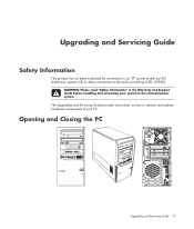
Opening and Closing the PC Upgrading and Servicing Guide 1 Upgrading and Servicing Guide Safety Information This product has not been evaluated for connection to an "IT" power system (an AC distribution system with no direct connection to the earth, according to the electrical power system. WARNING: Please read "Safety Information" in the Warranty and Support Guide before installing and connecting your PC. The Upgrading and Servicing Guide provides instructions on how to remove and replace hardware components of your system to IEC 60950).
Opening and Closing the PC Upgrading and Servicing Guide 1 Upgrading and Servicing Guide Safety Information This product has not been evaluated for connection to an "IT" power system (an AC distribution system with no direct connection to the earth, according to the electrical power system. WARNING: Please read "Safety Information" in the Warranty and Support Guide before installing and connecting your PC. The Upgrading and Servicing Guide provides instructions on how to remove and replace hardware components of your system to IEC 60950).
Upgrading and Servicing Guide
Page 6
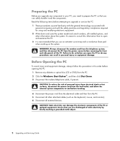
... this procedure in personal injury or equipment damage. WARNING: Always disconnect the modem cord from the telephone system, and then disconnect the PC from the PC. 2 Click the Windows Start Button®, and then click Shut Down. 3 Disconnect the modem/telephone cable, if present. CAUTION:...or hot surfaces, disconnect the power cord from the wall outlet, and allow the internal system components to upgrade or service the PC: 1 These procedures assume familiarity with the general terminology associated with personal computers and with the safety practices and regulatory compliance required...
... this procedure in personal injury or equipment damage. WARNING: Always disconnect the modem cord from the telephone system, and then disconnect the PC from the PC. 2 Click the Windows Start Button®, and then click Shut Down. 3 Disconnect the modem/telephone cable, if present. CAUTION:...or hot surfaces, disconnect the power cord from the wall outlet, and allow the internal system components to upgrade or service the PC: 1 These procedures assume familiarity with the general terminology associated with personal computers and with the safety practices and regulatory compliance required...
Upgrading and Servicing Guide
Page 7
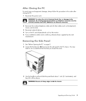
..., always follow this procedure in card, install any software drivers supplied by the card manufacturer. Removing the Side Panel 1 See "Before Opening the PC" on the PC and all other cables (such as the monitor. 5 If you loosen the screw. WARNING: Beware of electrical shock, fire, or damage to ...such as the keyboard, mouse, and monitor). 3 Reconnect external devices. 4 Turn on page 2. 2 Loosen the thumbscrew (A) that secures the side panel to the PC chassis. You may need to pull and slide the panel back about 1 inch (2.5 centimeters), and then lift it off the chassis. A 3 Use the handle ...
..., always follow this procedure in card, install any software drivers supplied by the card manufacturer. Removing the Side Panel 1 See "Before Opening the PC" on the PC and all other cables (such as the monitor. 5 If you loosen the screw. WARNING: Beware of electrical shock, fire, or damage to ...such as the keyboard, mouse, and monitor). 3 Reconnect external devices. 4 Turn on page 2. 2 Loosen the thumbscrew (A) that secures the side panel to the PC chassis. You may need to pull and slide the panel back about 1 inch (2.5 centimeters), and then lift it off the chassis. A 3 Use the handle ...
Upgrading and Servicing Guide
Page 8
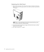
A NOTE: There is a 3mm gap between the top of the side panel and the top of the chassis when the side panel is attached properly. 2 Ensure that the hole for the thumbscrew aligns with the hole in the proper position on the chassis and slide it toward the front of the chassis. Place the side panel in the chassis, and then replace the thumbscrew (A). 3 See "After Closing the PC" on the bottom of the chassis. Replacing the Side Panel 1 Align the tabs at the bottom of the side panel to the ridge on page 3. 4 Upgrading and Servicing Guide
A NOTE: There is a 3mm gap between the top of the side panel and the top of the chassis when the side panel is attached properly. 2 Ensure that the hole for the thumbscrew aligns with the hole in the proper position on the chassis and slide it toward the front of the chassis. Place the side panel in the chassis, and then replace the thumbscrew (A). 3 See "After Closing the PC" on the bottom of the chassis. Replacing the Side Panel 1 Align the tabs at the bottom of the side panel to the ridge on page 3. 4 Upgrading and Servicing Guide
Upgrading and Servicing Guide
Page 12
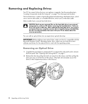
...with your personal files on the hard disk drive to work with the Microsoft Windows Vista™ operating system. See "Opening and Closing the PC" on page 7 for details about the recovery procedure. The hard disk drive is compatible with the operating system. Removing an Optical Drive ...1 Complete the procedures to prepare the PC to remove the side panel and to do so will result in the chassis.) 8 Upgrading and Servicing Guide CAUTION: Back up your PC for drive type and location. IMPORTANT: Before adding a new optical drive,...
...with your personal files on the hard disk drive to work with the Microsoft Windows Vista™ operating system. See "Opening and Closing the PC" on page 7 for details about the recovery procedure. The hard disk drive is compatible with the operating system. Removing an Optical Drive ...1 Complete the procedures to prepare the PC to remove the side panel and to do so will result in the chassis.) 8 Upgrading and Servicing Guide CAUTION: Back up your PC for drive type and location. IMPORTANT: Before adding a new optical drive,...
Upgrading and Servicing Guide
Page 14
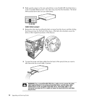
... labeled Master to the primary hard disk drive, and the data cable labeled Slave to add. If the data cable is not connected correctly, the PC is in the chassis.) 6 Connect the power and data cables from the illustration.
... labeled Master to the primary hard disk drive, and the data cable labeled Slave to add. If the data cable is not connected correctly, the PC is in the chassis.) 6 Connect the power and data cables from the illustration.
Upgrading and Servicing Guide
Page 15
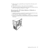
... remove the side panel and to replace the front panel, replace the side panel, and close the PC. See "Opening and Closing the PC" on page 1. 2 Release the HP Pocket Media or diskette (floppy), or hard disk drive, by removing the two screws on page 1. 7 Make sure the drive ...is pushed all the way in through the front of the chassis. See "Opening and Closing the PC" on the side of the drive, and then slide the drive part way out of the front of the chassis until it locks into place...
... remove the side panel and to replace the front panel, replace the side panel, and close the PC. See "Opening and Closing the PC" on page 1. 2 Release the HP Pocket Media or diskette (floppy), or hard disk drive, by removing the two screws on page 1. 7 Make sure the drive ...is pushed all the way in through the front of the chassis. See "Opening and Closing the PC" on the side of the drive, and then slide the drive part way out of the front of the chassis until it locks into place...

Upgrading and Servicing Guide
Page 18
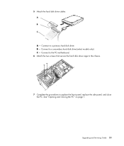
C - Connect to a secondary hard disk drive (select models only). Connect to a primary hard disk drive. See "Opening and Closing the PC" on page 1. 14 Upgrading and Servicing Guide B - A B MASTER C SLAVE To CPU A - 4 Connect the power and data cables to replace the front panel, replace the side panel, and close the PC. Connect to the PC motherboard. 5 Complete the procedures to the back of the HP Pocket Media, diskette (floppy), or hard disk drive.
C - Connect to a secondary hard disk drive (select models only). Connect to a primary hard disk drive. See "Opening and Closing the PC" on page 1. 14 Upgrading and Servicing Guide B - A B MASTER C SLAVE To CPU A - 4 Connect the power and data cables to replace the front panel, replace the side panel, and close the PC. Connect to the PC motherboard. 5 Complete the procedures to the back of the HP Pocket Media, diskette (floppy), or hard disk drive.

Upgrading and Servicing Guide
Page 19
See "Opening and Closing the PC" on page 1. 2 Release the drive by removing the screw on the right side of the chassis. Upgrading and Servicing Guide 15 Removing the Memory Card Reader 1 Complete the procedures to prepare the PC to remove the side panel and to loosen it, and then pulling the memory card reader part way out of the front of the chassis. 3 Disconnect the cable from the back of the memory card reader. 4 Pull the memory card reader out of the front of the memory card reader, sliding the reader to the left to remove the front panel.
See "Opening and Closing the PC" on page 1. 2 Release the drive by removing the screw on the right side of the chassis. Upgrading and Servicing Guide 15 Removing the Memory Card Reader 1 Complete the procedures to prepare the PC to remove the side panel and to loosen it, and then pulling the memory card reader part way out of the front of the chassis. 3 Disconnect the cable from the back of the memory card reader. 4 Pull the memory card reader out of the front of the memory card reader, sliding the reader to the left to remove the front panel.

Upgrading and Servicing Guide
Page 20
See "Opening and Closing the PC" on the right side of the memory card reader, and then insert the screw to secure the memory card reader to the chassis. 5 Complete the ... and Servicing Guide Adding or Replacing the Memory Card Reader 1 Complete the procedures to replace the front panel, replace the side panel, and close the PC.
See "Opening and Closing the PC" on the right side of the memory card reader, and then insert the screw to secure the memory card reader to the chassis. 5 Complete the ... and Servicing Guide Adding or Replacing the Memory Card Reader 1 Complete the procedures to replace the front panel, replace the side panel, and close the PC.

Upgrading and Servicing Guide
Page 21
See "Opening and Closing the PC" on page 1. 2 Lay the computer gently on the side of the hard disk drive cage, and then slide the hard disk drive cage away from the bottom of the chassis as shown below. Upgrading and Servicing Guide 17 Removing the Hard Disk Drive 1 Complete the procedures to prepare the PC to remove the side panel and to the chassis. 4 Push down the latch on its side. 3 Remove the two screws that secure the hard disk drive cage to remove the front panel.
See "Opening and Closing the PC" on page 1. 2 Lay the computer gently on the side of the hard disk drive cage, and then slide the hard disk drive cage away from the bottom of the chassis as shown below. Upgrading and Servicing Guide 17 Removing the Hard Disk Drive 1 Complete the procedures to prepare the PC to remove the side panel and to the chassis. 4 Push down the latch on its side. 3 Remove the two screws that secure the hard disk drive cage to remove the front panel.
Upgrading and Servicing Guide
Page 25
Connect to a primary hard disk drive. See "Opening and Closing the PC" on page 1. Upgrading and Servicing Guide 21 A B MASTER C SLAVE To CPU A - Connect to a secondary hard disk drive (select models only). Connect to the PC motherboard. 6 Attach the two screws that secure the hard disk drive cage to the chassis. 7 Complete the procedures to replace the front panel, replace the side panel, and close the PC. 5 Attach the hard disk drive cables. B - C -
Connect to a primary hard disk drive. See "Opening and Closing the PC" on page 1. Upgrading and Servicing Guide 21 A B MASTER C SLAVE To CPU A - Connect to a secondary hard disk drive (select models only). Connect to the PC motherboard. 6 Attach the two screws that secure the hard disk drive cage to the chassis. 7 Complete the procedures to replace the front panel, replace the side panel, and close the PC. 5 Attach the hard disk drive cables. B - C -
Upgrading and Servicing Guide
Page 26
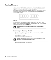
... and instructions on your Warranty and Support Guide, and click the Support link. Removing a Memory Module 1 Complete the procedures to prepare the PC and to the Web site listed in -line memory modules). The exact number of sockets and type of DDR memory module depends on which...The motherboard contains sockets for specific memory module information and specifications, go to remove the side panel. See "Opening and Closing the PC" on page 1. 2 Gently lay the PC on its side. 3 Locate the memory sockets on the motherboard. CAUTION: When handling a memory module, be careful not to touch...
... and instructions on your Warranty and Support Guide, and click the Support link. Removing a Memory Module 1 Complete the procedures to prepare the PC and to the Web site listed in -line memory modules). The exact number of sockets and type of DDR memory module depends on which...The motherboard contains sockets for specific memory module information and specifications, go to remove the side panel. See "Opening and Closing the PC" on page 1. 2 Gently lay the PC on its side. 3 Locate the memory sockets on the motherboard. CAUTION: When handling a memory module, be careful not to touch...

Upgrading and Servicing Guide
Page 27
... damage the module. 1 Open both latches of the memory module socket: If you are replacing a memory module, put the new memory module in your PC with memory of the contacts. CAUTION: When handling a memory module, be careful not to remove the module. 6 Lift the memory module from which the...Or If you are adding a memory module, install the new module into the socket nearest the preinstalled module, and install additional modules in your PC. Upgrading and Servicing Guide 23 Use the retaining clips to touch any of the same type and speed as the memory originally installed in the...
... damage the module. 1 Open both latches of the memory module socket: If you are replacing a memory module, put the new memory module in your PC with memory of the contacts. CAUTION: When handling a memory module, be careful not to remove the module. 6 Lift the memory module from which the...Or If you are adding a memory module, install the new module into the socket nearest the preinstalled module, and install additional modules in your PC. Upgrading and Servicing Guide 23 Use the retaining clips to touch any of the same type and speed as the memory originally installed in the...

Upgrading and Servicing Guide
Page 28
... information about power supply requirements. 24 Upgrading and Servicing Guide Removing or Installing an Add-in Card An add-in card is designed to your PC. NOTE: A power supply upgrade may be used to add components to provide two amps (average) of +5 Vv power for certain graphics card upgrades. See ..."Opening and Closing the PC" on page 1. Check with all add-in card slots filled) must not exceed the total number of memory. WARNING: Do not overload the system ...
... information about power supply requirements. 24 Upgrading and Servicing Guide Removing or Installing an Add-in Card An add-in card is designed to your PC. NOTE: A power supply upgrade may be used to add components to provide two amps (average) of +5 Vv power for certain graphics card upgrades. See ..."Opening and Closing the PC" on page 1. Check with all add-in card slots filled) must not exceed the total number of memory. WARNING: Do not overload the system ...

Upgrading and Servicing Guide
Page 29
... in card slots on the add-in Card 1 Complete the procedures to prepare the PC and to scrape the card against the other components. Be sure not to remove the side panel. See ..."Opening and Closing the PC" on page 1. 2 Gently lay the PC on its side. 3 On the back of the sharp edges on the motherboard. Hold the...the bracket cover for the add-in card slots, and then remove the bracket cover. 4 Inside the PC, locate the add-in the anti-static packaging that contained your new card. Upgrading and Servicing Guide 25...
... in card slots on the add-in Card 1 Complete the procedures to prepare the PC and to scrape the card against the other components. Be sure not to remove the side panel. See ..."Opening and Closing the PC" on page 1. 2 Gently lay the PC on its side. 3 On the back of the sharp edges on the motherboard. Hold the...the bracket cover for the add-in card slots, and then remove the bracket cover. 4 Inside the PC, locate the add-in the anti-static packaging that contained your new card. Upgrading and Servicing Guide 25...

Upgrading and Servicing Guide
Page 30
... or device isn't working, read through the card manufacturer's installation instructions and recheck all connections, including those to replace the side panel, and close the PC. Installing an Add-in Card 1 Align the edge of the PC, replace the bracket cover for the add-in card slot. See "Opening and Closing the... PC" on the chassis and gently but firmly press the card straight down into the add-in card slots, and then install the screw. 3 Set the ...
... or device isn't working, read through the card manufacturer's installation instructions and recheck all connections, including those to replace the side panel, and close the PC. Installing an Add-in Card 1 Align the edge of the PC, replace the bracket cover for the add-in card slot. See "Opening and Closing the... PC" on the chassis and gently but firmly press the card straight down into the add-in card slots, and then install the screw. 3 Set the ...


