
Service Guide
Page 4
... 4-5 5 Removal and Replacement Procedures 5.1 Serial Number 5-1 5.2 Disassembly Sequence Chart 5-2 5.3 Preparing the Notebook for Disassembly 5-4 5.4 Notebook Feet 5-9 5.5 Memory Module 5-10 5.6 Mini PCI Communications Board 5-12 5.7 Keyboard Cover 5-14 5.8 Keyboard 5-16 5.9 Switch Board 5-19 5.10 Speakers 5-21 5.11 Optical Drive 5-22 5.12 Display Assembly 5-23 5.13 Top Cover 5-27 5.14 Heat Sink 5-31 5.15 Processor...
... 4-5 5 Removal and Replacement Procedures 5.1 Serial Number 5-1 5.2 Disassembly Sequence Chart 5-2 5.3 Preparing the Notebook for Disassembly 5-4 5.4 Notebook Feet 5-9 5.5 Memory Module 5-10 5.6 Mini PCI Communications Board 5-12 5.7 Keyboard Cover 5-14 5.8 Keyboard 5-16 5.9 Switch Board 5-19 5.10 Speakers 5-21 5.11 Optical Drive 5-22 5.12 Display Assembly 5-23 5.13 Top Cover 5-27 5.14 Heat Sink 5-31 5.15 Processor...
Service Guide
Page 16
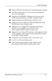
Product Description ■ Full-size Windows keyboard with embedded numeric keypad ■ TouchPad pointing device with on button and dedicated...■ Support for 1 or 2 Type II PC Card slots, with support for both 32-bit (CardBus) and 16-bit PC Cards (HP Compaq nx9040 notebook models only) ■ Support for 2 or 2 Type I PC Card slots, with support for both 32...-bit (CardBus) and 16-bit PC Cards (all notebook models except HP Compaq nx9040) ■ External 65-watt AC adapter with 3-wire power cord ■ 6-cell or 8-cell Li...
Product Description ■ Full-size Windows keyboard with embedded numeric keypad ■ TouchPad pointing device with on button and dedicated...■ Support for 1 or 2 Type II PC Card slots, with support for both 32-bit (CardBus) and 16-bit PC Cards (HP Compaq nx9040 notebook models only) ■ Support for 2 or 2 Type I PC Card slots, with support for both 32...-bit (CardBus) and 16-bit PC Cards (all notebook models except HP Compaq nx9040) ■ External 65-watt AC adapter with 3-wire power cord ■ 6-cell or 8-cell Li...
Service Guide
Page 26
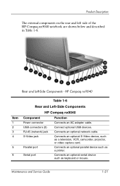
Product Description The external components on the rear and left side of the HP Compaq nx9040 notebook are shown below and described in Table 1-6. Connects an optional network cable. Connects an optional serial device such as a television, ...and Service Guide 1-21 Connect optional USB devices. Connects an optional S-Video device, such as keyboard or mouse. Rear and Left-Side Components - HP Compaq nx9040 Item 1 2 3 4 5 6 Table 1-6 Rear and Left-Side Components HP Compaq nx9040 Component Power connector USB connectors (2) RJ-45 (network) jack S-Video jack Parallel port ...
Product Description The external components on the rear and left side of the HP Compaq nx9040 notebook are shown below and described in Table 1-6. Connects an optional network cable. Connects an optional serial device such as a television, ...and Service Guide 1-21 Connect optional USB devices. Connects an optional S-Video device, such as keyboard or mouse. Rear and Left-Side Components - HP Compaq nx9040 Item 1 2 3 4 5 6 Table 1-6 Rear and Left-Side Components HP Compaq nx9040 Component Power connector USB connectors (2) RJ-45 (network) jack S-Video jack Parallel port ...

Service Guide
Page 28
Product Description The notebook keyboard components on the HP Pavilion ze4900 notebook are shown below and described in Table 1-7. HP Pavilion ze4900 Maintenance and Service Guide 1-23 Keyboard Components -
Product Description The notebook keyboard components on the HP Pavilion ze4900 notebook are shown below and described in Table 1-7. HP Pavilion ze4900 Maintenance and Service Guide 1-23 Keyboard Components -

Service Guide
Page 29
...) Perform system and application tasks. Keypad keys (15) In Windows, can be used like the keys on the caps lock light. Product Description Item 1 2 3 4 5 6 7 8 Table 1-7 Keyboard Components HP Pavilion ze4900 Component Function num lock key Enables numeric lock, turns on the embedded numeric keypad, and turns on the num lock light...
...) Perform system and application tasks. Keypad keys (15) In Windows, can be used like the keys on the caps lock light. Product Description Item 1 2 3 4 5 6 7 8 Table 1-7 Keyboard Components HP Pavilion ze4900 Component Function num lock key Enables numeric lock, turns on the embedded numeric keypad, and turns on the num lock light...
Service Guide
Page 30
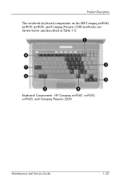
HP Compaq nx9040, nx9030, nx9020, and Compaq Presario 2200 Maintenance and Service Guide 1-25 Keyboard Components - Product Description The notebook keyboard components on the HP Compaq nx9040, nx9030, nx9020, and Compaq Presario 2200 notebooks are shown below and described in Table 1-8.
HP Compaq nx9040, nx9030, nx9020, and Compaq Presario 2200 Maintenance and Service Guide 1-25 Keyboard Components - Product Description The notebook keyboard components on the HP Compaq nx9040, nx9030, nx9020, and Compaq Presario 2200 notebooks are shown below and described in Table 1-8.

Service Guide
Page 31
caps lock key Enables caps lock and turns on the num lock light. Product Description Item 1 2 3 4 5 6 7 8 Table 1-8 Keyboard Components HP Compaq nx9040, nx9030, nx9020, and Compaq Presario 2200 Component Function num lock key Enables numeric lock, turns on the embedded numeric keypad, and turns on the caps lock light. For example, pressing fn+...
caps lock key Enables caps lock and turns on the num lock light. Product Description Item 1 2 3 4 5 6 7 8 Table 1-8 Keyboard Components HP Compaq nx9040, nx9030, nx9020, and Compaq Presario 2200 Component Function num lock key Enables numeric lock, turns on the embedded numeric keypad, and turns on the caps lock light. For example, pressing fn+...
Service Guide
Page 38
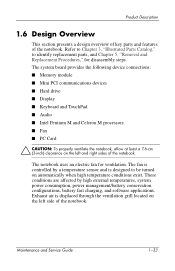
... for disassembly steps. The system board provides the following device connections: ■ Memory module ■ Mini PCI communications devices ■ Hard drive ■ Display ■ Keyboard and TouchPad ■ Audio ■ Intel Pentium M and Celeron M processors ■ Fan ■ PC Card Ä CAUTION: To properly ventilate the notebook, allow at least...
... for disassembly steps. The system board provides the following device connections: ■ Memory module ■ Mini PCI communications devices ■ Hard drive ■ Display ■ Keyboard and TouchPad ■ Audio ■ Intel Pentium M and Celeron M processors ■ Fan ■ PC Card Ä CAUTION: To properly ventilate the notebook, allow at least...

Service Guide
Page 45
... "Flowchart 2.14-No Audio." Y Go to Y "Flowchart 2.8-No Operating System (OS) Loading." End Go to "Flowchart 2.16-Nonfunction ing Keyboard" or "Flowchart 2.17-Nonfunction ing Pointing Device." Go to "Flowchart 2.15-Nonfunction ing Device." Troubleshooting Flowchart 2.1-Initial Troubleshooting Begin ...2.2-No Power, Part 1." Maintenance and Service Guide 2-7 Y Go to "Flowchart 2.18-No Network/Modem Connection." N Keyboard/ pointing device working ? Go to "Flowchart 2.6-No Video, Part 1." Y N Is there video? (no boot) Y N Is the OS loading? N ...
... "Flowchart 2.14-No Audio." Y Go to Y "Flowchart 2.8-No Operating System (OS) Loading." End Go to "Flowchart 2.16-Nonfunction ing Keyboard" or "Flowchart 2.17-Nonfunction ing Pointing Device." Go to "Flowchart 2.15-Nonfunction ing Device." Troubleshooting Flowchart 2.1-Initial Troubleshooting Begin ...2.2-No Power, Part 1." Maintenance and Service Guide 2-7 Y Go to "Flowchart 2.18-No Network/Modem Connection." N Keyboard/ pointing device working ? Go to "Flowchart 2.6-No Video, Part 1." Y N Is there video? (no boot) Y N Is the OS loading? N ...

Service Guide
Page 60
Connect notebook to good external keyboard. Y Replace system board. Y Done OK? Troubleshooting Flowchart 2.16-Nonfunctioning Keyboard Keyboard not operating properly. Reseat internal keyboard connector (if applicable). N Replace system board. Done 2-22 Maintenance and Service Guide Y Replace internal keyboard or cable. N External device works? N OK?
Connect notebook to good external keyboard. Y Replace system board. Y Done OK? Troubleshooting Flowchart 2.16-Nonfunctioning Keyboard Keyboard not operating properly. Reseat internal keyboard connector (if applicable). N Replace system board. Done 2-22 Maintenance and Service Guide Y Replace internal keyboard or cable. N External device works? N OK?
Service Guide
Page 65
...15.0-inch, XGA 14.1-inch, XGA 371772-001 371771-001 for use on Compaq Presario 2200 notebook models 15.0-inch, XGA 14.1-inch, XGA 371770-001 371769-001 Display screw covers (not illustrated) 371813-001 Keyboard covers (includes speaker grilles and switch board) for use on HP Pavilion ...ze4900 notebook models for use on HP Compaq nx9040, nx9030, and nx9020 notebook models for use on Compaq Presario 2200 notebook models 371802-001 371804-001 371803-001 ...
...15.0-inch, XGA 14.1-inch, XGA 371772-001 371771-001 for use on Compaq Presario 2200 notebook models 15.0-inch, XGA 14.1-inch, XGA 371770-001 371769-001 Display screw covers (not illustrated) 371813-001 Keyboard covers (includes speaker grilles and switch board) for use on HP Pavilion ...ze4900 notebook models for use on HP Compaq nx9040, nx9030, and nx9020 notebook models for use on Compaq Presario 2200 notebook models 371802-001 371804-001 371803-001 ...
Service Guide
Page 67
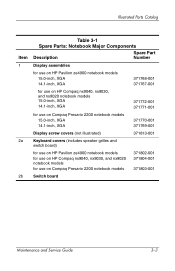
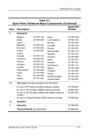
Illustrated Parts Catalog Table 3-1 Spare Parts: Notebook Major Components (Continued) Item Description Spare Part Number 3 Keyboards Belgium Brazil Czech Republic Denmark France French Canada Germany Greece Hungary Iceland International Israel Italy Japan 371787-181 371787-201 371787...includes speakers and TouchPad) for use in HP Pavilion ze4900 notebook models for use in HP Compaq nx9040 notebook models for use in HP Compaq nx9030 and nx9020 notebook models for use in Compaq Presario 2200 notebook models 371799-001 373291-001 371801-001 371800-001 4b Speakers 5 Heat sink 371796-...
Illustrated Parts Catalog Table 3-1 Spare Parts: Notebook Major Components (Continued) Item Description Spare Part Number 3 Keyboards Belgium Brazil Czech Republic Denmark France French Canada Germany Greece Hungary Iceland International Israel Italy Japan 371787-181 371787-201 371787...includes speakers and TouchPad) for use in HP Pavilion ze4900 notebook models for use in HP Compaq nx9040 notebook models for use in HP Compaq nx9030 and nx9020 notebook models for use in Compaq Presario 2200 notebook models 371799-001 373291-001 371801-001 371800-001 4b Speakers 5 Heat sink 371796-...

Service Guide
Page 85
... Chart Use the chart below to determine the section number to remove hard drive bezel Notebook feet 0 Memory module 2 loosened Mini PCI communications board 2 loosened Keyboard cover 2 Keyboard 4 Switch board 2 on all notebook models except HP Pavilion ze4900 1 on HP Pavilion ze4900 Speakers 4 Optical drive 2 Display assembly 10 Top cover 20 Heat...
... Chart Use the chart below to determine the section number to remove hard drive bezel Notebook feet 0 Memory module 2 loosened Mini PCI communications board 2 loosened Keyboard cover 2 Keyboard 4 Switch board 2 on all notebook models except HP Pavilion ze4900 1 on HP Pavilion ze4900 Speakers 4 Optical drive 2 Display assembly 10 Top cover 20 Heat...
Service Guide
Page 97
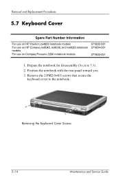
Removing the Keyboard Cover Screws 5-14 Maintenance and Service Guide Position the notebook with the rear panel toward you. 3. Prepare the notebook for disassembly (Section 5.3). 2. Remove the 2 PM2.0×6.0 screws that secure the keyboard cover to the notebook. Removal and Replacement Procedures 5.7 Keyboard Cover Spare Part Number Information For use on HP Pavilion ze4900 notebook models For use on HP Compaq nx9040, nx9030, and nx9020 notebook models For use on Compaq Presario 2200 notebook models 371802-001 371804-001 371803-001 1.
Removing the Keyboard Cover Screws 5-14 Maintenance and Service Guide Position the notebook with the rear panel toward you. 3. Prepare the notebook for disassembly (Section 5.3). 2. Remove the 2 PM2.0×6.0 screws that secure the keyboard cover to the notebook. Removal and Replacement Procedures 5.7 Keyboard Cover Spare Part Number Information For use on HP Pavilion ze4900 notebook models For use on HP Compaq nx9040, nx9030, and nx9020 notebook models For use on Compaq Presario 2200 notebook models 371802-001 371804-001 371803-001 1.

Service Guide
Page 98
Press and hold the f8 key 2 and use a flat tool to separate the cover from the notebook. 9. Removing the Keyboard Cover Reverse the above procedure to separate the cover from the notebook. 10. Open the notebook as far as possible. 6. Press and hold the f11 ... the notebook display-side up to separate the cover from the notebook 5. Press and hold the f3 key 1 and use a flat tool to install an keyboard cover.
Press and hold the f8 key 2 and use a flat tool to separate the cover from the notebook. 9. Removing the Keyboard Cover Reverse the above procedure to separate the cover from the notebook. 10. Open the notebook as far as possible. 6. Press and hold the f11 ... the notebook display-side up to separate the cover from the notebook 5. Press and hold the f3 key 1 and use a flat tool to install an keyboard cover.

Service Guide
Page 99
Remove the keyboard cover (Section 5.7). 5-16 Maintenance and Service Guide Prepare the notebook for disassembly (Section 5.3). 2. Removal and Replacement Procedures 5.8 Keyboard Spare Part Number Information Belgium Brazil Czech Republic Denmark France French Canada Germany Greece Hungary Iceland International Israel Italy Japan Korea 371787-181 371787-201 ...
Remove the keyboard cover (Section 5.7). 5-16 Maintenance and Service Guide Prepare the notebook for disassembly (Section 5.3). 2. Removal and Replacement Procedures 5.8 Keyboard Spare Part Number Information Belgium Brazil Czech Republic Denmark France French Canada Germany Greece Hungary Iceland International Israel Italy Japan Korea 371787-181 371787-201 ...

Service Guide
Page 100
Lift the back edge of the keyboard and swing it forward until it rests on the palm rest 3. Remove the 3 PM2.0×4.0 screws 1 and 1 PM2.0×3.0 screw 2 that secure the keyboard to the notebook. 4. Releasing the Keyboard Maintenance and Service Guide 5-17 Removal and Replacement Procedures 3.
Lift the back edge of the keyboard and swing it forward until it rests on the palm rest 3. Remove the 3 PM2.0×4.0 screws 1 and 1 PM2.0×3.0 screw 2 that secure the keyboard to the notebook. 4. Releasing the Keyboard Maintenance and Service Guide 5-17 Removal and Replacement Procedures 3.

Service Guide
Page 101
Removal and Replacement Procedures 5. Release the zero insertion force (ZIF) connector 1 to install the keyboard. 5-18 Maintenance and Service Guide Remove the keyboard. Removing the Keyboard Reverse the above procedure to which the keyboard cable is attached and disconnect the cable 2. 6.
Removal and Replacement Procedures 5. Release the zero insertion force (ZIF) connector 1 to install the keyboard. 5-18 Maintenance and Service Guide Remove the keyboard. Removing the Keyboard Reverse the above procedure to which the keyboard cable is attached and disconnect the cable 2. 6.

Service Guide
Page 102
Remove the keyboard (Section 5.8). 4. Refer to Section 5.7, "Keyboard Cover," for disassembly (Section 5.3). 2. Remove the keyboard cover (Section 5.7). 3. Removing the Switch Board Maintenance and Service Guide 5-19 Removal and Replacement Procedures 5.9 Switch Board ✎ The switch board is included with the keyboard cover. Disconnect the display lid switch 1 and speaker cables 2 from the switch board. Prepare the notebook for spare part number information. 1.
Remove the keyboard (Section 5.8). 4. Refer to Section 5.7, "Keyboard Cover," for disassembly (Section 5.3). 2. Remove the keyboard cover (Section 5.7). 3. Removing the Switch Board Maintenance and Service Guide 5-19 Removal and Replacement Procedures 5.9 Switch Board ✎ The switch board is included with the keyboard cover. Disconnect the display lid switch 1 and speaker cables 2 from the switch board. Prepare the notebook for spare part number information. 1.

Service Guide
Page 104
Remove the keyboard (Section 5.8). 4. Removal and Replacement Procedures 5.10 Speakers ✎ The speakers are included with the top cover. Remove the 4 PM2.0×3.0 screws 2 that secure the left .... Maintenance and Service Guide 5-21 Prepare the notebook for spare part number information. 1. Removing the Speakers Reverse the above procedure to the notebook. 6. Remove the keyboard cover (Section 5.7). 3. Disconnect the speaker cable from the switch board 1. 5.
Remove the keyboard (Section 5.8). 4. Removal and Replacement Procedures 5.10 Speakers ✎ The speakers are included with the top cover. Remove the 4 PM2.0×3.0 screws 2 that secure the left .... Maintenance and Service Guide 5-21 Prepare the notebook for spare part number information. 1. Removing the Speakers Reverse the above procedure to the notebook. 6. Remove the keyboard cover (Section 5.7). 3. Disconnect the speaker cable from the switch board 1. 5.


