Instruction Manual
Page 2
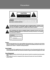
...These servicing instructions are qualified to do not perform any servicing other end to constitute a risk of electric shock, do so. Power Management: •• Before plugging the power cord into the AC outlet, make sure that is intended to alert the user to persons. Model No. If the unit will...the unit rear panel and the other than that may be used for a long period of time, disconnect the power and remove the batteries from the outlet. Power Supply: Connect one end of the supplied power cord to manual for a long time, disconnect the plug from the remote. Refer to the...
...These servicing instructions are qualified to do not perform any servicing other end to constitute a risk of electric shock, do so. Power Management: •• Before plugging the power cord into the AC outlet, make sure that is intended to alert the user to persons. Model No. If the unit will...the unit rear panel and the other than that may be used for a long period of time, disconnect the power and remove the batteries from the outlet. Power Supply: Connect one end of the supplied power cord to manual for a long time, disconnect the plug from the remote. Refer to the...
Instruction Manual
Page 4
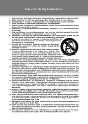
... of the plug. See the operating instructions for replacement or directions to qualified service personnel. This will only fit into such power lines or circuits. Do not use a mounting accessory recommended by the manufacturer. 999 A product and cart combination should be moved with them ... or near a bath tub, washbowl, kitchen sink, laundry tub, in the cabinet are unable to protect it can fall into the power outlet in the operating instructions should be routed so that has one direction. Important Safety Instructions 111 Read Instructions: All the safety and ...
... of the plug. See the operating instructions for replacement or directions to qualified service personnel. This will only fit into such power lines or circuits. Do not use a mounting accessory recommended by the manufacturer. 999 A product and cart combination should be moved with them ... or near a bath tub, washbowl, kitchen sink, laundry tub, in the cabinet are unable to protect it can fall into the power outlet in the operating instructions should be routed so that has one direction. Important Safety Instructions 111 Read Instructions: All the safety and ...
Instruction Manual
Page 5
... the service technician to perform safety checks to ensure that your service technician has used replacement parts specified by following conditions: a) when the power-supply or plug is in damage and will often require extensive work by a qualified technician to restore the product to its normal operation...
... the service technician to perform safety checks to ensure that your service technician has used replacement parts specified by following conditions: a) when the power-supply or plug is in damage and will often require extensive work by a qualified technician to restore the product to its normal operation...
Instruction Manual
Page 8
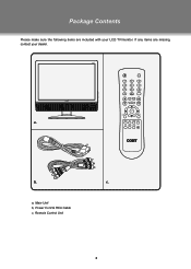
a. c. a, Main Unit b, Power Cord & RCA Cable c, Remote Control Unit 2 b. If any items are included with your dealer. Package Contents Please make sure the following items are missing, contact your LCD TV/monitor.
a. c. a, Main Unit b, Power Cord & RCA Cable c, Remote Control Unit 2 b. If any items are included with your dealer. Package Contents Please make sure the following items are missing, contact your LCD TV/monitor.
Instruction Manual
Page 9
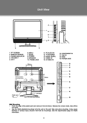
... Wall Mounting •• Pinch the edge of the plastic part and remove it fall from its mountings. POWER INDICATOR 4. AUDIO IN((R/L) 14. TFTV1923 Rear Cabinet) 16. See the Specification page for VESA informaiton. 3 TV ANTENNA 13. S-VIDEO IN < > > VESA Standard mounting thread x 4 < 100mm > Plastic part x 2 Unit Stand (e.g. SPEAKER 10. VOLUME-/+ 5. Unit...
... Wall Mounting •• Pinch the edge of the plastic part and remove it fall from its mountings. POWER INDICATOR 4. AUDIO IN((R/L) 14. TFTV1923 Rear Cabinet) 16. See the Specification page for VESA informaiton. 3 TV ANTENNA 13. S-VIDEO IN < > > VESA Standard mounting thread x 4 < 100mm > Plastic part x 2 Unit Stand (e.g. SPEAKER 10. VOLUME-/+ 5. Unit...
Instruction Manual
Page 10
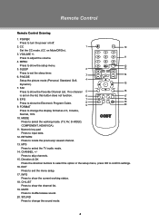
... 9. MTS Press to input data. 12. MODE Press to show the Favorite Channel List. Numeric key pad Press to select the TV audio mode. 14. RETURN Press to skip channels. 15. Press to locate the previously viewed channel. 13. INFO Press to select...Normal, 16:9. 10. If no channel 5 16 is set the sleep timer. 3 14 6. FORMAT 9 19 20 Press to turn the power on Mute/Off/On). 3. CHANNEL +/- FAV Press to confirm settings. 16. Direction & OK Press the direction buttons to select the option in...
... 9. MTS Press to input data. 12. MODE Press to show the Favorite Channel List. Numeric key pad Press to select the TV audio mode. 14. RETURN Press to skip channels. 15. Press to locate the previously viewed channel. 13. INFO Press to select...Normal, 16:9. 10. If no channel 5 16 is set the sleep timer. 3 14 6. FORMAT 9 19 20 Press to turn the power on Mute/Off/On). 3. CHANNEL +/- FAV Press to confirm settings. 16. Direction & OK Press the direction buttons to select the option in...
Instruction Manual
Page 12
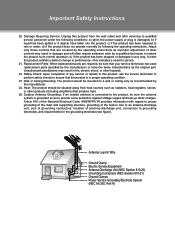
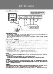
Cable Connections Figure. Cable connections Set the unit into the relative input mode to the antenna port. External AV Source Antenna/Power Connection 111 Connect TV RF sources to enable the signal pass. These HDMI input connectors are capable of the AV cable is for the audio conneciton ... to the player's power jack and the other end to connect outdoor antenna. 222 Insert one end of connection that transmits digital audio and video signals simultaneously over a single cable. VGA Input The VGA port of the TV is required for the video connection. A HDMI cable is capable of...
Cable Connections Figure. Cable connections Set the unit into the relative input mode to the antenna port. External AV Source Antenna/Power Connection 111 Connect TV RF sources to enable the signal pass. These HDMI input connectors are capable of the AV cable is for the audio conneciton ... to the player's power jack and the other end to connect outdoor antenna. 222 Insert one end of connection that transmits digital audio and video signals simultaneously over a single cable. VGA Input The VGA port of the TV is required for the video connection. A HDMI cable is capable of...
Instruction Manual
Page 13
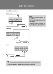
The white/red plug of the external sources as well. 7 AV Input NOTE: 111 Be sure to have all necessary connections properly done before connect the power supply. 222 When input the AV signal, refer to the manual of the AV cable can also be used separately to input the audio signal in the S-video/Component connection. Cable connections Component Input S-Video Input NOTE: We supply the AV cable and the power cord with this product. The white/red plug of the AV cable is for the audio connection and the yellow plug for the video connection. Cable Connections Figure.
The white/red plug of the external sources as well. 7 AV Input NOTE: 111 Be sure to have all necessary connections properly done before connect the power supply. 222 When input the AV signal, refer to the manual of the AV cable can also be used separately to input the audio signal in the S-video/Component connection. Cable connections Component Input S-Video Input NOTE: We supply the AV cable and the power cord with this product. The white/red plug of the AV cable is for the audio connection and the yellow plug for the video connection. Cable Connections Figure.
Instruction Manual
Page 14
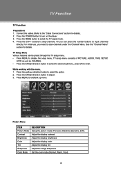
... Adjust the image sharpness Set the color mode (Normal, Warm, Cool). 8 See the "Channel Menu" section for details). 222 Press the POWER button to turn on the player. 333 Press the MODE button to input channels directly. buttons to scan channels under the Channel Menu.... TV Function TV Function Preparations 111 Connect the cables.(Refer to the "Cable Connections" section for details. TV Setup Menu Various features can press the number buttons to select the TV signal mode. 444 Press the CH+/- While working with ...
... Adjust the image sharpness Set the color mode (Normal, Warm, Cool). 8 See the "Channel Menu" section for details). 222 Press the POWER button to turn on the player. 333 Press the MODE button to input channels directly. buttons to scan channels under the Channel Menu.... TV Function TV Function Preparations 111 Connect the cables.(Refer to the "Cable Connections" section for details. TV Setup Menu Various features can press the number buttons to select the TV signal mode. 444 Press the CH+/- While working with ...
Instruction Manual
Page 20
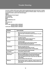
Address COBY Electronics Technical Support 56-65 Rust Street Maspeth, NY 11378 Email [email protected] Web www.cobyusa.com Phone 800-727-3592: Weekdays 8:30AM -9:00PM EST Saturdays 9:00AM -5:30PM EST 718-416-3197: Weekdays 8:00AM -5:30PM EST Symptom No Power No Picture No Sound Color ... •• Make sure the unit has been powered on manually. •• Check if the power cord has been properly connected to the power outlet. •• Check if the main power has been switched on. •• Try another TV channel •• Check if the system connection...
Address COBY Electronics Technical Support 56-65 Rust Street Maspeth, NY 11378 Email [email protected] Web www.cobyusa.com Phone 800-727-3592: Weekdays 8:30AM -9:00PM EST Saturdays 9:00AM -5:30PM EST 718-416-3197: Weekdays 8:00AM -5:30PM EST Symptom No Power No Picture No Sound Color ... •• Make sure the unit has been powered on manually. •• Check if the power cord has been properly connected to the power outlet. •• Check if the main power has been switched on. •• Try another TV channel •• Check if the system connection...
Instruction Manual
Page 21
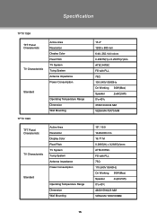
Specification TFTV 1524 TFT Panel Characteristic TV Charactoristic Active Area Resolution Display Color Pixel Pitch TV System Tuing System Antenna Impedance Power Consumption Standard TFTV 1923 Operating Temperature Range Dimension Wall Mounting TFT Panel Characteristic TV Charactoristic Active Area Resolution Display Color Pixel Pitch TV System Tuing System Antenna Impedance Power Consumption Standard Operating Temperature Range Dimension...
Specification TFTV 1524 TFT Panel Characteristic TV Charactoristic Active Area Resolution Display Color Pixel Pitch TV System Tuing System Antenna Impedance Power Consumption Standard TFTV 1923 Operating Temperature Range Dimension Wall Mounting TFT Panel Characteristic TV Charactoristic Active Area Resolution Display Color Pixel Pitch TV System Tuing System Antenna Impedance Power Consumption Standard Operating Temperature Range Dimension...
Instruction Manual
Page 22
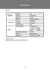
Specification TFTV 2224 TFT Panel Characteristic TV Charactoristic Active Area Resolution Display Color Pixel Pitch TV System Tuing System Antenna Impedance Power Consumption Standard Operating Temperature Range Dimension Wall Mounting 22" 1680x1050 mm 16.77 M 0.282(H) x 0.282(V)mm ATSC/NTSC FS with PLL 75Ω 110-240V 50/60Hz On Working 60W(Max) Speaker 2x(4Ω,5W) 0ºc-40ºc 527x167x444 MM VESA M4, 100 X 100 MM P/N: 907-FV15-2400-00R Specifications and manual are subject to change without prior notice. 16
Specification TFTV 2224 TFT Panel Characteristic TV Charactoristic Active Area Resolution Display Color Pixel Pitch TV System Tuing System Antenna Impedance Power Consumption Standard Operating Temperature Range Dimension Wall Mounting 22" 1680x1050 mm 16.77 M 0.282(H) x 0.282(V)mm ATSC/NTSC FS with PLL 75Ω 110-240V 50/60Hz On Working 60W(Max) Speaker 2x(4Ω,5W) 0ºc-40ºc 527x167x444 MM VESA M4, 100 X 100 MM P/N: 907-FV15-2400-00R Specifications and manual are subject to change without prior notice. 16


