User Manual
Page 9
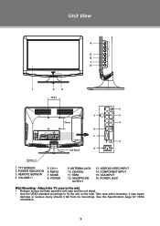
... COAXIAL 11. COMPONENT INPUT 15. See the Specification page for VESA informaiton. 3 HDMI 12. Attach the TV case to the wall •• Release screws and take apart the unit case and the unit stand. •• Use the VESA standard mountings to fix the unit on the wall. CH...or serious injury should it fall from its mountings. Unit View 4 5 6 7 8 1 2 3 75mm < > > < 12 9 13 75mm 14 10 > 11 15 16 Unit Stand Screw x 2 1. REMOTE SENSOR 4. VGA INPUT 16. ANTENNA JACK 10. TFT SCREEN 2. MENU 7. POWER JACK Wall Mounting - POWER 9. VIDEO/S-VIDEO INPUT 14.
... COAXIAL 11. COMPONENT INPUT 15. See the Specification page for VESA informaiton. 3 HDMI 12. Attach the TV case to the wall •• Release screws and take apart the unit case and the unit stand. •• Use the VESA standard mountings to fix the unit on the wall. CH...or serious injury should it fall from its mountings. Unit View 4 5 6 7 8 1 2 3 75mm < > > < 12 9 13 75mm 14 10 > 11 15 16 Unit Stand Screw x 2 1. REMOTE SENSOR 4. VGA INPUT 16. ANTENNA JACK 10. TFT SCREEN 2. MENU 7. POWER JACK Wall Mounting - POWER 9. VIDEO/S-VIDEO INPUT 14.


