User Manual
Page 2
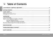
English ÂÂ Table of Contents Location of Controls and Parts 3 Getting Started...5 Power Supply...5 Battery Back-Up...5 Setting the Correct Time...5 Operation...6 Using the Radio...6 Alarm Timer (Wake to Radio or Buzzer 6 Snooze Delayed Alarm...6 Sleep or Sleep-and-Wake to Radio 7 Auxiliary Audio Input From External Device 7 Specifications...8 Troubleshooting & Support...9 Safety Notices...11 Page 2 Table Of Contents
English ÂÂ Table of Contents Location of Controls and Parts 3 Getting Started...5 Power Supply...5 Battery Back-Up...5 Setting the Correct Time...5 Operation...6 Using the Radio...6 Alarm Timer (Wake to Radio or Buzzer 6 Snooze Delayed Alarm...6 Sleep or Sleep-and-Wake to Radio 7 Auxiliary Audio Input From External Device 7 Specifications...8 Troubleshooting & Support...9 Safety Notices...11 Page 2 Table Of Contents
User Manual
Page 3
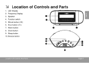
Hour button ( H ) 7. Sleep button 10. Snooze button 6 5 4 10 Location Of Controls And Parts 3 7 8 9 Page 3 English Function switch 2 5. Alarm button 3 8. ÂÂ Location of Controls and Parts 1. LED Display 2. Minute button ( M ) 6. Speaker 1 4. Frequency Display 3. Clock button 9.
Hour button ( H ) 7. Sleep button 10. Snooze button 6 5 4 10 Location Of Controls And Parts 3 7 8 9 Page 3 English Function switch 2 5. Alarm button 3 8. ÂÂ Location of Controls and Parts 1. LED Display 2. Minute button ( M ) 6. Speaker 1 4. Frequency Display 3. Clock button 9.
User Manual
Page 4
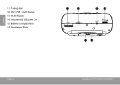
AUX IN jack 14. Volume dial ( Buzzer On ) 15. Tuning dial 12. Battery compartment 16. AM / FM / AUX Switch 13. Ventilation Slots 11 12 13 14 15 16 Page 4 Location Of Controls And Parts English 11.
AUX IN jack 14. Volume dial ( Buzzer On ) 15. Tuning dial 12. Battery compartment 16. AM / FM / AUX Switch 13. Ventilation Slots 11 12 13 14 15 16 Page 4 Location Of Controls And Parts English 11.
User Manual
Page 5
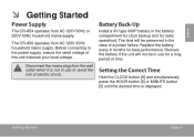
... is displayed. Battery Back-Up Install a 9V type 006P battery in use for a long period of a power failure. Setting the Correct Time Hold the CLOCK button [8] and simultaneously press the HOUR button [6] or MINUTE button [5] until the desired time is not in the battery compartment for clock backup (not for best performance. Getting Started Page 5 Replace the battery every 6 months for radio operation). English ÂÂ Getting Started Power Supply The CR-A54 operates from...
... is displayed. Battery Back-Up Install a 9V type 006P battery in use for a long period of a power failure. Setting the Correct Time Hold the CLOCK button [8] and simultaneously press the HOUR button [6] or MINUTE button [5] until the desired time is not in the battery compartment for clock backup (not for best performance. Getting Started Page 5 Replace the battery every 6 months for radio operation). English ÂÂ Getting Started Power Supply The CR-A54 operates from...
User Manual
Page 6
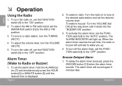
... sound again 9 minutes later. To adjust the volume level, turn the radio off the alarm timer, set the alarm timer: hold the ALARM button [7] and simultaneously press the HOUR button [6] or MINUTE button [5] until it clicks into the "BUZZER ON" position. 3. To wake to the "ON" position. 2. The alarm timer will light up . 4. When the alarm timer reaches the set time, the radio or buzzer will activate to the desired radio station and set the FUNCTION switch [4] to the "AUTO" position. Operation...
... sound again 9 minutes later. To adjust the volume level, turn the radio off the alarm timer, set the alarm timer: hold the ALARM button [7] and simultaneously press the HOUR button [6] or MINUTE button [5] until it clicks into the "BUZZER ON" position. 3. To wake to the "ON" position. 2. The alarm timer will light up . 4. When the alarm timer reaches the set time, the radio or buzzer will activate to the desired radio station and set the FUNCTION switch [4] to the "AUTO" position. Operation...
User Manual
Page 7
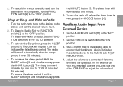
... SLEEP button [9] and simultaneously press Operation the MINUTE button [5]. Use a 3.5mm male to male audio cable to connect the Headphone / Audio Out jack of the external device to the AUX IN jack [13] of the CRA-54/50 to "1:59" (1 hour and 59 minutes). To Sleep-and-Wake to Radio: Set the FUNCTION switch [4] to indicate the default sleep period. The clock will decrease by one minute. 5. Page 7 English 2. The sleep timer will display...
... SLEEP button [9] and simultaneously press Operation the MINUTE button [5]. Use a 3.5mm male to male audio cable to connect the Headphone / Audio Out jack of the external device to the AUX IN jack [13] of the CRA-54/50 to "1:59" (1 hour and 59 minutes). To Sleep-and-Wake to Radio: Set the FUNCTION switch [4] to indicate the default sleep period. The clock will decrease by one minute. 5. Page 7 English 2. The sleep timer will display...
User Manual
Page 8
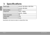
Page 8 Specifications English ÂÂ Specifications Power supply: Back-up battery: Frequencies: Power consumption: Output power: Speaker: CR-A54: 120V 60Hz or 220V 50Hz CR-A50: 120V 60Hz DC 9 V FM 88 - 108MHz AM 530 - 1700KHz 3W 0.5W 8 ohm Specifications and manual are subject to change without notice.
Page 8 Specifications English ÂÂ Specifications Power supply: Back-up battery: Frequencies: Power consumption: Output power: Speaker: CR-A54: 120V 60Hz or 220V 50Hz CR-A50: 120V 60Hz DC 9 V FM 88 - 108MHz AM 530 - 1700KHz 3W 0.5W 8 ohm Specifications and manual are subject to change without notice.

User Manual
Page 9
... do not resolve the problem, please contact Technical Support. English ÂÂ Troubleshooting & Support If you have a problem with this unit, please read the troubleshooting guide below and check our website at www.cobyusa.com for Frequently Asked Questions (FAQ) and product updates. Address Email Web Phone Coby Electronics Technical Support 150 Knowlton Way Savannah, Georgia 31407 [email protected] www.cobyusa.com 800-727...
... do not resolve the problem, please contact Technical Support. English ÂÂ Troubleshooting & Support If you have a problem with this unit, please read the troubleshooting guide below and check our website at www.cobyusa.com for Frequently Asked Questions (FAQ) and product updates. Address Email Web Phone Coby Electronics Technical Support 150 Knowlton Way Savannah, Georgia 31407 [email protected] www.cobyusa.com 800-727...
User Manual
Page 10
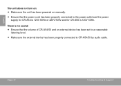
English The unit does not turn on. Make sure the unit has been powered on manually. Ensure that the volume of CR-A54/50 and or external device has been set to a reasonable listening level. Make sure the external device has been properly connected to the power outlet and the power supply for CR-A54 is 120V 60Hz or 220V 50Hz and for CR-A50 is 120V 60Hz. Page 10 Troubleshooting & Support There is no sound. Ensure that the power cord has been properly connected to CR-A54/50 by audio cable.
English The unit does not turn on. Make sure the unit has been powered on manually. Ensure that the volume of CR-A54/50 and or external device has been set to a reasonable listening level. Make sure the external device has been properly connected to the power outlet and the power supply for CR-A54 is 120V 60Hz or 220V 50Hz and for CR-A50 is 120V 60Hz. Page 10 Troubleshooting & Support There is no sound. Ensure that the power cord has been properly connected to CR-A54/50 by audio cable.
User Manual
Page 11
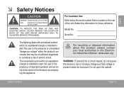
... to alert the user to the presence of important operation and servicing instructions in the literature accompanying the appliance. Dangerous high voltage is located on the rear of the unit. For recycling or disposal information about this information for future reference. Retain this product, please contact your local authorities or the Electronics Industries Alliance: www.eiae.org...
... to alert the user to the presence of important operation and servicing instructions in the literature accompanying the appliance. Dangerous high voltage is located on the rear of the unit. For recycling or disposal information about this information for future reference. Retain this product, please contact your local authorities or the Electronics Industries Alliance: www.eiae.org...
User Manual
Page 12
... interference in a particular installation. This equipment generates, uses and can be required to the following measures: • Reorient or relocate the receiving antenna. • Increase the separation between the equipment and receiver. • Connect the equipment into an outlet on , the user is subject to stop operation of the FCC Rules. If such changes or modifications should be...
... interference in a particular installation. This equipment generates, uses and can be required to the following measures: • Reorient or relocate the receiving antenna. • Increase the separation between the equipment and receiver. • Connect the equipment into an outlet on , the user is subject to stop operation of the FCC Rules. If such changes or modifications should be...
User Manual
Page 13
... to your home, consult your product dealer or local power company. Use a damp cloth for ventilation to ensure reliable operation of the product and to the operating instructions. 12. Water and Moisture: Do not use this product from battery power or other attachments may be followed. 5. This plug will only fit into the outlet, try reversing the direction of power supply to insert the plug fully into...
... to your home, consult your product dealer or local power company. Use a damp cloth for ventilation to ensure reliable operation of the product and to the operating instructions. 12. Water and Moisture: Do not use this product from battery power or other attachments may be followed. 5. This plug will only fit into the outlet, try reversing the direction of power supply to insert the plug fully into...
User Manual
Page 14
... been exposed to qualified service personnel. 19. Replacement Parts: When replacement parts are not likely to its normal operation; This will often require extensive work by following conditions: a) when the power-supply or plug is left unattended and unused for service. 20. When installing an outside antenna system should not be walked on the product. 18. Servicing: Do not attempt to cords at plugs, convenience receptacles, and...
... been exposed to qualified service personnel. 19. Replacement Parts: When replacement parts are not likely to its normal operation; This will often require extensive work by following conditions: a) when the power-supply or plug is left unattended and unused for service. 20. When installing an outside antenna system should not be walked on the product. 18. Servicing: Do not attempt to cords at plugs, convenience receptacles, and...
User Manual
Page 15
Safety Notices Page 15 English Wall or Ceiling Mounting: The product should be mounted to ensure that produce heat. Heat: The product should be situated away from heat sources such as recommended by the manufacturer. 23. 21. Safety Check: Upon completion of any service or repairs to this product, ask the service technician to perform safety checks to a wall or ceiling only as radiators, heat registers, stoves, or other products (including amplifiers) that the product is in proper operating condition. 22.
Safety Notices Page 15 English Wall or Ceiling Mounting: The product should be mounted to ensure that produce heat. Heat: The product should be situated away from heat sources such as recommended by the manufacturer. 23. 21. Safety Check: Upon completion of any service or repairs to this product, ask the service technician to perform safety checks to a wall or ceiling only as radiators, heat registers, stoves, or other products (including amplifiers) that the product is in proper operating condition. 22.


