29LTDCHR_MANL
Page 1
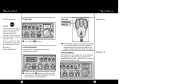
Mic Cord • RF Gain 1 How to Use Your Contents Cobra 29 LTD CHR Features 1 The CB Story A1 FCC Regulations FCC Warnings Included Accessories Controls & Indicators A2 Our Thanks to You A3 Customer Support Installation Location 2 Mounting and Connection 2 Antennas CB Antenna 6 Marine Installation 6 Ignition Noise Interference 7 Operating Your 29 LTD CHR Turning On Your CB 8 Setting Channel Selector 9 Calibrate For SWR (Standing Wave Ratio 10 To Receive 13...
Mic Cord • RF Gain 1 How to Use Your Contents Cobra 29 LTD CHR Features 1 The CB Story A1 FCC Regulations FCC Warnings Included Accessories Controls & Indicators A2 Our Thanks to You A3 Customer Support Installation Location 2 Mounting and Connection 2 Antennas CB Antenna 6 Marine Installation 6 Ignition Noise Interference 7 Operating Your 29 LTD CHR Turning On Your CB 8 Setting Channel Selector 9 Calibrate For SWR (Standing Wave Ratio 10 To Receive 13...
29LTDCHR_MANL
Page 2
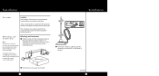
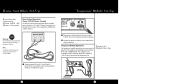
... not interfere with the driver or passenger. The mounting must be mechanically strong, conveniently located. 3 Connect the antenna cable plug to the receptacle marked "ANT" on the back of transceiver and microphone bracket before starting the installation. The transceiver is no interference, remove the bracket and use it . Mounting and Connection 1 Hold the radio with the microphone bracket beside it as...
... not interfere with the driver or passenger. The mounting must be mechanically strong, conveniently located. 3 Connect the antenna cable plug to the receptacle marked "ANT" on the back of transceiver and microphone bracket before starting the installation. The transceiver is no interference, remove the bracket and use it . Mounting and Connection 1 Hold the radio with the microphone bracket beside it as...
29LTDCHR_MANL
Page 3
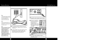
Be sure to observe polarity markings. 7 Mount the microphone bracket on bracket securely. 5 Bracket should be used. 4 6 Plug power cable into back of the two) to the negative side of the unit (driver's left on accidentally, and also permits operating the unit without running...power cord to an accessory 12 volt fuse. 5 Connect the black lead to the engine block (or chassis). This is the larger of unit marked "Power". Installation Installation Note Connecting to receptacle, on the front of unit and install unit on either side of the vehicle. Note Before installing the CB radio...
Be sure to observe polarity markings. 7 Mount the microphone bracket on bracket securely. 5 Bracket should be used. 4 6 Plug power cable into back of the two) to the negative side of the unit (driver's left on accidentally, and also permits operating the unit without running...power cord to an accessory 12 volt fuse. 5 Connect the black lead to the engine block (or chassis). This is the larger of unit marked "Power". Installation Installation Note Connecting to receptacle, on the front of unit and install unit on either side of the vehicle. Note Before installing the CB radio...
29LTDCHR_MANL
Page 4
... critical in affecting transmission distance. Cobra loaded type antenna models are also available which allow maximum power output. Even though the Cobra 29 LTD CHR has an automatic noise limiter, in some installations ignition interference may be grounded to the chassis via a ground strap when antenna is mounted on the mirror bracket. CB Antenna Since the maximum allowable power output of the transmitter is limited by...
... critical in affecting transmission distance. Cobra loaded type antenna models are also available which allow maximum power output. Even though the Cobra 29 LTD CHR has an automatic noise limiter, in some installations ignition interference may be grounded to the chassis via a ground strap when antenna is mounted on the mirror bracket. CB Antenna Since the maximum allowable power output of the transmitter is limited by...
29LTDCHR_MANL
Page 5
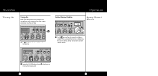
Operation Turning On Turning On Make sure the power cord, antenna and microphone are connected to a normal listening level. 8 9 Setting Channel Selector Operation Setting Channel Selector 1 The CB/PA button should be in the CB position. 1 Select one of forty channels and adjust volume. The selected channel is indicated by the LED readout directly above the channel selector knob 2 Rotate the On/Off Volume knob clockwise to their proper connectors before starting.
Operation Turning On Turning On Make sure the power cord, antenna and microphone are connected to a normal listening level. 8 9 Setting Channel Selector Operation Setting Channel Selector 1 The CB/PA button should be in the CB position. 1 Select one of forty channels and adjust volume. The selected channel is indicated by the LED readout directly above the channel selector knob 2 Rotate the On/Off Volume knob clockwise to their proper connectors before starting.

29LTDCHR_MANL
Page 6
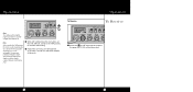
...complete information). 2 Switch to the CAL position. 10 4 While holding mic button adjust the SWR CAL knob so the meter needle swings to the CAL M mark on the meter (located on the right). Note Antenna Indicator LED will illuminate when TX if SWR ...antenna directions for SWR (Standing Wave Ratio) SWR calibration is done to properly adjust the length of the antenna and to achieve optimum performance. Operation Note Calibration must be made in an open area (never in order to monitor the quality of the coaxial cable and all RF connections. This calibration is high. 1 Select channel...
...complete information). 2 Switch to the CAL position. 10 4 While holding mic button adjust the SWR CAL knob so the meter needle swings to the CAL M mark on the meter (located on the right). Note Antenna Indicator LED will illuminate when TX if SWR ...antenna directions for SWR (Standing Wave Ratio) SWR calibration is done to properly adjust the length of the antenna and to achieve optimum performance. Operation Note Calibration must be made in an open area (never in order to monitor the quality of the coaxial cable and all RF connections. This calibration is high. 1 Select channel...
29LTDCHR_MANL
Page 7
... SWR position the meter needle should ideally be as possible. A slight antenna height adjustment (higher or lower) may be illuminated. 12 13 Anything over 3 is not acceptable. Operation To Receive Operation To Receive Note The reading will be slightly higher on Channel 1 and 40. Repeat relcalibration steps. 5 While still holding down the mic button, set the S/RF SWR...
... SWR position the meter needle should ideally be as possible. A slight antenna height adjustment (higher or lower) may be illuminated. 12 13 Anything over 3 is not acceptable. Operation To Receive Operation To Receive Note The reading will be slightly higher on Channel 1 and 40. Repeat relcalibration steps. 5 While still holding down the mic button, set the S/RF SWR...

29LTDCHR_MANL
Page 8
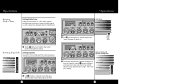
... Operation Selecting A Channel Selecting A Channel Operation NB-ANL/ANL/OFF (Noise Blanker/Automatic Noise Limiter) Switch NB-ANL/ANL/ OFF (Noise Blanker / Automatic Noise Limiter) Switch S-Meter 1 Switch to NOR to OFF position all noise filtration will be turned off. 1 The S/RF-SWR-CAL switch must... be in reducing repetitive noises such as ignition interference. When switched to select desired channel.
... Operation Selecting A Channel Selecting A Channel Operation NB-ANL/ANL/OFF (Noise Blanker/Automatic Noise Limiter) Switch NB-ANL/ANL/ OFF (Noise Blanker / Automatic Noise Limiter) Switch S-Meter 1 Switch to NOR to OFF position all noise filtration will be turned off. 1 The S/RF-SWR-CAL switch must... be in reducing repetitive noises such as ignition interference. When switched to select desired channel.

29LTDCHR_MANL
Page 9
Note The RF Gain is used to optimize reception in weak signal areas. 1 Rotate the RF Gain knob counterclockwise to reduce gain in strong or weak signal areas. In weak signal areas turn clockwise to control brightness of the channel indicator and multi-function meter for day or nighttime driving. RF Gain Control 1 Switch to BRT or DIM to increase gain. 16 17 Operation Bright/Dim Switch Bright/Dim Switch Operation RF Gain Control The RF Gain is used to optimize reception in strong signal areas.
Note The RF Gain is used to optimize reception in weak signal areas. 1 Rotate the RF Gain knob counterclockwise to reduce gain in strong or weak signal areas. In weak signal areas turn clockwise to control brightness of the channel indicator and multi-function meter for day or nighttime driving. RF Gain Control 1 Switch to BRT or DIM to increase gain. 16 17 Operation Bright/Dim Switch Bright/Dim Switch Operation RF Gain Control The RF Gain is used to optimize reception in strong signal areas.
29LTDCHR_MANL
Page 10
... to enter. 18 Gate set to Desired Squelch Setting (DSS) 3 To achieve the Desired Squelch Setting (DSS), turn the control clockwise just until you to capture a more readable signal, as well as a "fine tune" control enabling you hear noise. This is the "control gate" for optimum tuning. Operation Setting Delta-Tune Setting Delta-Tune Delta-Tune functions as eliminate adjacent channel interference.
... to enter. 18 Gate set to Desired Squelch Setting (DSS) 3 To achieve the Desired Squelch Setting (DSS), turn the control clockwise just until you to capture a more readable signal, as well as a "fine tune" control enabling you hear noise. This is the "control gate" for optimum tuning. Operation Setting Delta-Tune Setting Delta-Tune Delta-Tune functions as eliminate adjacent channel interference.
29LTDCHR_MANL
Page 11
Prolonged transmitting without an antenna, or a poorly matched antenna, could cause damage to read the F.C.C. Transmit Operation Transmit 1 Push and hold the microphone two inches from your mouth and speak in some conditions. 20 21 Be sure the antenna is now activated.When transmitting, hold mic button to transmit.Transmitter is properly connected to adjust the desired amount of modulation talk back that...
Prolonged transmitting without an antenna, or a poorly matched antenna, could cause damage to read the F.C.C. Transmit Operation Transmit 1 Push and hold the microphone two inches from your mouth and speak in some conditions. 20 21 Be sure the antenna is now activated.When transmitting, hold mic button to transmit.Transmitter is properly connected to adjust the desired amount of modulation talk back that...

29LTDCHR_MANL
Page 12
...Cobra external speakers are rated at least 4.0 watts. External Speaker 1 Connect an external speaker to handle at 10 watts. 22 23 Note The external speaker should have 8-ohm impedance and be in , the internal speaker is automatically disconnected. Operation RF Meter RF Meter This meter swings proportionately to the RF output (outgoing signal) while transmitting.... 1 The S/RF-SWR-CAL switch must be rated to the external...
...Cobra external speakers are rated at least 4.0 watts. External Speaker 1 Connect an external speaker to handle at 10 watts. 22 23 Note The external speaker should have 8-ohm impedance and be in , the internal speaker is automatically disconnected. Operation RF Meter RF Meter This meter swings proportionately to the RF output (outgoing signal) while transmitting.... 1 The S/RF-SWR-CAL switch must be rated to the external...
29LTDCHR_MANL
Page 14
... (-) leads of the transceiver to observe polarity markings. 3 Connect properly installed and matched base station antenna. Note For further information call Cobra Customer Service 773.889.3087. 2 Plug power cable into back of the power pack. 26 27 This adapter and a magnetic mount antenna allow you will need a 13.8 volt DC Power Pack rated at a minimum of 2 amps, and a properly...
... (-) leads of the transceiver to observe polarity markings. 3 Connect properly installed and matched base station antenna. Note For further information call Cobra Customer Service 773.889.3087. 2 Plug power cable into back of the power pack. 26 27 This adapter and a magnetic mount antenna allow you will need a 13.8 volt DC Power Pack rated at a minimum of 2 amps, and a properly...
29LTDCHR_MANL
Page 15
... Messages Note If no response on channel 9, try channels 19 or 14. • Warn of traffic problems • Provide weather and road data • Provide help needed. C. You cannot use CB to channel 9 for channel 9. F. Set to promote illegal activities. Type. Bring sailboat into port." No "Attention motorists. All quiet." 29 Number. Yes "Out of an emergency...
... Messages Note If no response on channel 9, try channels 19 or 14. • Warn of traffic problems • Provide weather and road data • Provide help needed. C. You cannot use CB to channel 9 for channel 9. F. Set to promote illegal activities. Type. Bring sailboat into port." No "Attention motorists. All quiet." 29 Number. Yes "Out of an emergency...
29LTDCHR_MANL
Page 16
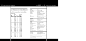
...mic 10-93 Check my frequency on this station 10-35 Confidential information 10-36 Correct time is up for contact 10-30 Does not conform to FCC rules 10-33 Emergency traffic 10-34 Trouble at this channel... 10-94 Give me a long count 10-99 Mission completed, all units secure 10-200 Police needed 10-39 Message delivered 10-41 Turn to 10-64 Net clear 10-65 Awaiting your station 30 How Your CB Can Serve You Code Meaning 10-29...poorly Receiving well Stop transmitting OK, message received Relay message Busy, stand by Out of service, leaving In service, subject to call ...
...mic 10-93 Check my frequency on this station 10-35 Confidential information 10-36 Correct time is up for contact 10-30 Does not conform to FCC rules 10-33 Emergency traffic 10-34 Trouble at this channel... 10-94 Give me a long count 10-99 Mission completed, all units secure 10-200 Police needed 10-39 Message delivered 10-41 Turn to 10-64 Net clear 10-65 Awaiting your station 30 How Your CB Can Serve You Code Meaning 10-29...poorly Receiving well Stop transmitting OK, message received Relay message Busy, stand by Out of service, leaving In service, subject to call ...
29LTDCHR_MANL
Page 17
... Control Adjustable for inputs from 10 to cause cancer and birth defects or other reproductive harm.. SO-239 Meter Illuminated; Wash hands after handling. 32 33 Frequency Ranges 29 LTD CHR Specifications The COBRA 29 LTD CHR transceiver represents one of all 40 CB channels. indicates relative power output, received signal strength and VSWR TRANSMITTER Power Output 4 watts Modulation AM (Amplitude Modulation) Frequency Response 300 to 3000 Hz Output Impedance...
... Control Adjustable for inputs from 10 to cause cancer and birth defects or other reproductive harm.. SO-239 Meter Illuminated; Wash hands after handling. 32 33 Frequency Ranges 29 LTD CHR Specifications The COBRA 29 LTD CHR transceiver represents one of all 40 CB channels. indicates relative power output, received signal strength and VSWR TRANSMITTER Power Output 4 watts Modulation AM (Amplitude Modulation) Frequency Response 300 to 3000 Hz Output Impedance...

29LTDCHR_MANL
Page 18
... COBRA ELECTRONICS CORPORATION warrants that the product is repaired or replaced under warranty. This warranty may also have other damages; This warranty gives you specific legal rights, and you . 34 Replacement DC Power Cord For in vehicle use 426-002-N-001 Replacement Mounting Bracket For in vehicle use 251-353-9-001 Replacement Thumb Screws For in vehicle use 634-081-9-001 Replacement Microphone Bracket...
... COBRA ELECTRONICS CORPORATION warrants that the product is repaired or replaced under warranty. This warranty may also have other damages; This warranty gives you specific legal rights, and you . 34 Replacement DC Power Cord For in vehicle use 426-002-N-001 Replacement Mounting Bracket For in vehicle use 251-353-9-001 Replacement Thumb Screws For in vehicle use 634-081-9-001 Replacement Microphone Bracket...
29LTDCHR_MANL
Page 19
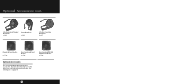
See ordering info on page 37. 36 Optional Accessories cont. 4 Pin Replacement Dynamic Microphone HG M73 Power Microphone HG M75 4 Pin Noise Canceling Microphone HG M77 Dynamic External Speaker HG S100 Noise Canceling External Speaker HG S300 Noise Canceling With Talk Back External Speaker HG S500 Optional Accessories • You can find quality Cobra products and accessories at your local Cobra dealer, or in the U.S.A., you can order directly from Cobra.
See ordering info on page 37. 36 Optional Accessories cont. 4 Pin Replacement Dynamic Microphone HG M73 Power Microphone HG M75 4 Pin Noise Canceling Microphone HG M77 Dynamic External Speaker HG S100 Noise Canceling External Speaker HG S300 Noise Canceling With Talk Back External Speaker HG S500 Optional Accessories • You can find quality Cobra products and accessories at your local Cobra dealer, or in the U.S.A., you can order directly from Cobra.

29LTDCHR_MANL
Page 20
... to be returned. 4. Microphone bracket 5. A Consumer Service Representative can assist you by e-mail to obtain an operator's license. Ship prepaid and insured by Cobra, may be asked questions about Cobra products. (773) 889-3087 24 hours a day, 7 days a week. Replacement or substitution of transistors, regular diodes or other parts of a unique nature, with Your 29 LTD CHR 1. What's Included with...
... to be returned. 4. Microphone bracket 5. A Consumer Service Representative can assist you by e-mail to obtain an operator's license. Ship prepaid and insured by Cobra, may be asked questions about Cobra products. (773) 889-3087 24 hours a day, 7 days a week. Replacement or substitution of transistors, regular diodes or other parts of a unique nature, with Your 29 LTD CHR 1. What's Included with...
29LTDCHR_MANL
Page 21
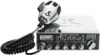
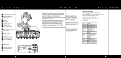
.... Customer Support Should you for pricing or visit www.cobra.com. Call 773-889-3087 for purchasing the Cobra 29 LTD CHR CB Radio. For Credit Card Orders Call 773-889-3087 [Press one from the main menu] 8:00 a.m. RX (Receive)/ TX (Transmit) LED Indicator 15 14 13 12 11 10 11. Antenna Connector 21. to You 1. 4-Pin Microphone Connector...
.... Customer Support Should you for pricing or visit www.cobra.com. Call 773-889-3087 for purchasing the Cobra 29 LTD CHR CB Radio. For Credit Card Orders Call 773-889-3087 [Press one from the main menu] 8:00 a.m. RX (Receive)/ TX (Transmit) LED Indicator 15 14 13 12 11 10 11. Antenna Connector 21. to You 1. 4-Pin Microphone Connector...


