
Hardware Maintenance Manual
Page 2
...other technical information regarding the products contained in accordance with Cisco's installation instructions, it is , make certain the equipment and the television or radio are on a different circuit from this software without specific prior written permission. All rights reserved. Copyright ©... interference to radio or television reception, try to correct the interference by Cisco Systems, Inc. The X Window System is causing interference by Madge Networks Limited. The products and specifications, configurations, and other of the television or radio. • Move ...
...other technical information regarding the products contained in accordance with Cisco's installation instructions, it is , make certain the equipment and the television or radio are on a different circuit from this software without specific prior written permission. All rights reserved. Copyright ©... interference to radio or television reception, try to correct the interference by Cisco Systems, Inc. The X Window System is causing interference by Madge Networks Limited. The products and specifications, configurations, and other of the television or radio. • Move ...

Hardware Maintenance Manual
Page 3
...to cooperate with the Documentation, for such tests. Further, Customer agrees to the published specifications for a remedy, Customer must report all copyright, confidentiality, and proprietary notices that Cisco or its networks without payment of the hardware less depreciation calculated on a straight-line... basis. In no event does Cisco warrant that aspects of the licensed materials, including the specific design and structure of individual programs, constitute trade secrets and/or copyrighted material of their ...
...to cooperate with the Documentation, for such tests. Further, Customer agrees to the published specifications for a remedy, Customer must report all copyright, confidentiality, and proprietary notices that Cisco or its networks without payment of the hardware less depreciation calculated on a straight-line... basis. In no event does Cisco warrant that aspects of the licensed materials, including the specific design and structure of individual programs, constitute trade secrets and/or copyrighted material of their ...

Hardware Maintenance Manual
Page 5
TABLE OF CONTENTS About This Manual xv Document Objectives xv Audience xv Document Organization xv Document Conventions xvi Chapter 1 Cisco 4000 Series Overview 1-1 External Differences in Models of the Cisco 4000 Series 1-1 Series Specifications 1-2 Memory Systems 1-4 Chapter 2 Preparing for Installation 2-1 Safety Recommendations 2-2 Safety with Electricity 2-2 Preventing Electrostatic Discharge Damage 2-3 General Site Requirements 2-3 Site Environment...
TABLE OF CONTENTS About This Manual xv Document Objectives xv Audience xv Document Organization xv Document Conventions xvi Chapter 1 Cisco 4000 Series Overview 1-1 External Differences in Models of the Cisco 4000 Series 1-1 Series Specifications 1-2 Memory Systems 1-4 Chapter 2 Preparing for Installation 2-1 Safety Recommendations 2-2 Safety with Electricity 2-2 Preventing Electrostatic Discharge Damage 2-3 General Site Requirements 2-3 Site Environment...

Hardware Maintenance Manual
Page 7
Testing Your Installation 5-20 Recovering a Lost Password 5-21 Appendix A Cabling Specifications A-1 EIA/TIA-232 Console and Auxiliary Port Pinouts A-2 Serial Cable Pinouts A-3 EIA/TIA-232 Dual Serial Module Cable ...Changing Configuration Register Settings B-2 Configuring the Boot Field B-3 Enabling Booting from Flash Memory B-6 Appendix C Cisco 4000-M ROM Monitor C-1 Entering the Cisco 4000-M ROM Monitor Program C-1 Available ROM Monitor Commands C-2 Appendix D Cisco 4500-M and Cisco 4700 ROM Monitor D-1 Entering the ROM Monitor Program D-1 Available ROM Monitor Commands D-2 ROM Monitor ...
Testing Your Installation 5-20 Recovering a Lost Password 5-21 Appendix A Cabling Specifications A-1 EIA/TIA-232 Console and Auxiliary Port Pinouts A-2 Serial Cable Pinouts A-3 EIA/TIA-232 Dual Serial Module Cable ...Changing Configuration Register Settings B-2 Configuring the Boot Field B-3 Enabling Booting from Flash Memory B-6 Appendix C Cisco 4000-M ROM Monitor C-1 Entering the Cisco 4000-M ROM Monitor Program C-1 Available ROM Monitor Commands C-2 Appendix D Cisco 4500-M and Cisco 4700 ROM Monitor D-1 Entering the ROM Monitor Program D-1 Available ROM Monitor Commands D-2 ROM Monitor ...

Hardware Maintenance Manual
Page 13
... A-10 Table A-11 Table A-12 Table A-13 Table A-14 Table A-15 Table A-16 Table A-17 Table A-18 Table A-19 Table A-20 Cisco 4000 Series Physical Specifications 1-3 Cisco 4000 Series Processor and Memory Specifications 1-3 Unit Numbering for Dual Serial, Ethernet, and Token Ring Modules 2-7 Unit Numbering Addresses for Dual Serial and Two Ethernet Modules 2-8 Unit...
... A-10 Table A-11 Table A-12 Table A-13 Table A-14 Table A-15 Table A-16 Table A-17 Table A-18 Table A-19 Table A-20 Cisco 4000 Series Physical Specifications 1-3 Cisco 4000 Series Processor and Memory Specifications 1-3 Unit Numbering for Dual Serial, Ethernet, and Token Ring Modules 2-7 Unit Numbering Addresses for Dual Serial and Two Ethernet Modules 2-8 Unit...

Hardware Maintenance Manual
Page 15
Use this publication follow: • Chapter 1, "Cisco 4000 Series Overview," contains an overview of the Cisco 4000 series features and physical specifications. • Chapter 2, "Preparing for Installation," includes safety recommendations, tools and equipment, site requirements, an ...practices and have experience as an annual subscription. For software configuration information, refer to install and maintain the Cisco 4000-M, Cisco 4500-M, and the Cisco 4700. Audience This publication is available both as a single CD and as an electronic or electromechanical technician...
Use this publication follow: • Chapter 1, "Cisco 4000 Series Overview," contains an overview of the Cisco 4000 series features and physical specifications. • Chapter 2, "Preparing for Installation," includes safety recommendations, tools and equipment, site requirements, an ...practices and have experience as an annual subscription. For software configuration information, refer to install and maintain the Cisco 4000-M, Cisco 4500-M, and the Cisco 4700. Audience This publication is available both as a single CD and as an electronic or electromechanical technician...

Hardware Maintenance Manual
Page 16
...([ ]) are optional. • Alternative but required keywords are grouped in the paragraph. Note Means reader take note. xvi Cisco 4000 Series Hardware Installation and Maintenance Document Conventions • Chapter 4, "Troubleshooting the Initial Hardware Configuration," includes a troubleshooting overview, ...or adding network processor modules, and replacing single in-line memory modules (SIMMs). • Appendix A, "Cabling Specifications," provides cable illustrations, cable pinouts, and signal descriptions for the console and auxiliary ports, synchronous serial cables, and Ethernet ...
...([ ]) are optional. • Alternative but required keywords are grouped in the paragraph. Note Means reader take note. xvi Cisco 4000 Series Hardware Installation and Maintenance Document Conventions • Chapter 4, "Troubleshooting the Initial Hardware Configuration," includes a troubleshooting overview, ...or adding network processor modules, and replacing single in-line memory modules (SIMMs). • Appendix A, "Cabling Specifications," provides cable illustrations, cable pinouts, and signal descriptions for the console and auxiliary ports, synchronous serial cables, and Ethernet ...

Hardware Maintenance Manual
Page 20
...Channelized E1/ISDN PRI network interface module ((NP-CE1). Series Specifications Figure 1-1 shows the front panel of the single and dual Token Ring, dual Ethernet, and FDDI modules. 1-2 Cisco 4000 Series Hardware Installation and Maintenance Network processor modules can support... Ethernet network processor module and early versions of a Cisco 4000 series router. Figure 1-1 Cisco 4000 Series Chassis-Front Panel 1 DATA OK 2 DATA OK 3 DATA OK OK POWER SERIES H3590 Series Specifications Design specifications for the Cisco 4000 series follow: • Modular router platform &#...
...Channelized E1/ISDN PRI network interface module ((NP-CE1). Series Specifications Figure 1-1 shows the front panel of the single and dual Token Ring, dual Ethernet, and FDDI modules. 1-2 Cisco 4000 Series Hardware Installation and Maintenance Network processor modules can support... Ethernet network processor module and early versions of a Cisco 4000 series router. Figure 1-1 Cisco 4000 Series Chassis-Front Panel 1 DATA OK 2 DATA OK 3 DATA OK OK POWER SERIES H3590 Series Specifications Design specifications for the Cisco 4000 series follow: • Modular router platform &#...

Hardware Maintenance Manual
Page 21
... Series Processor and Memory Specifications Description Processor Main Memory (DRAM)2 Cisco 4000-M Cisco 4500-M Cisco 4700 40-MHz Motorola 68EC030 100-MHz IDT Orion RISC1 133-MHz...pin-compatible. 2. Cisco 4000 Series Overview 1-3 Table 1-2 lists the processor and memory specifications for the Cisco 4000 series routers. ROM-Read-only memory. AWG-American Wire Gauge 2. Series Specifications Table 1-1 lists the physical specifications for the Cisco 4000 series routers. Table 1-1 Cisco 4000 Series Physical Specifications Description Design Specification Dimensions (W x D...
... Series Processor and Memory Specifications Description Processor Main Memory (DRAM)2 Cisco 4000-M Cisco 4500-M Cisco 4700 40-MHz Motorola 68EC030 100-MHz IDT Orion RISC1 133-MHz...pin-compatible. 2. Cisco 4000 Series Overview 1-3 Table 1-2 lists the processor and memory specifications for the Cisco 4000 series routers. ROM-Read-only memory. AWG-American Wire Gauge 2. Series Specifications Table 1-1 lists the physical specifications for the Cisco 4000 series routers. Table 1-1 Cisco 4000 Series Physical Specifications Description Design Specification Dimensions (W x D...

Hardware Maintenance Manual
Page 25
... circuitry. They protect the chassis and provide a nonskid surface. Preventing Electrostatic Discharge Damage Electrostatic discharge (ESD) can result in wet locations unless the jack is specifically designed for wet locations. • Never touch uninsulated telephone wires or terminals unless the telephone line is properly prepared before beginning installation. If you isolate...
... circuitry. They protect the chassis and provide a nonskid surface. Preventing Electrostatic Discharge Damage Electrostatic discharge (ESD) can result in wet locations unless the jack is specifically designed for wet locations. • Never touch uninsulated telephone wires or terminals unless the telephone line is properly prepared before beginning installation. If you isolate...

Hardware Maintenance Manual
Page 27
... completed Initial system operation verified Verified by Router name Router serial number Notes: Date Preparing for each system Background information placed in Site Log Environmental specifications verified Site power voltages verified Installation site prepower check completed Required tools available Additional equipment available Router received Printed documentation or UniverCD received (if ordered...
... completed Initial system operation verified Verified by Router name Router serial number Notes: Date Preparing for each system Background information placed in Site Log Environmental specifications verified Site power voltages verified Installation site prepower check completed Required tools available Additional equipment available Router received Printed documentation or UniverCD received (if ordered...

Hardware Maintenance Manual
Page 31
...baud • 8 data bits • No parity generated or checked • 2 stop bits In the appendix "Cabling Specifications," Table A-1 lists the pinout for the Cisco 4000-M console port and Table A-2 lists the pinout for Installation 2-9 Auxiliary Port Connections A male DB-25 connector auxiliary port... port (female DB-25 connector) wired as a data communications equipment (DCE) device. In the appendix "Cabling Specifications," Table A-1 lists the pinout for the Cisco 4000-M and Table A-2 lists the pinout for network access. Figure 2-4 Slot Filler Panel Console Port and Auxiliary ...
...baud • 8 data bits • No parity generated or checked • 2 stop bits In the appendix "Cabling Specifications," Table A-1 lists the pinout for the Cisco 4000-M console port and Table A-2 lists the pinout for Installation 2-9 Auxiliary Port Connections A male DB-25 connector auxiliary port... port (female DB-25 connector) wired as a data communications equipment (DCE) device. In the appendix "Cabling Specifications," Table A-1 lists the pinout for the Cisco 4000-M and Table A-2 lists the pinout for network access. Figure 2-4 Slot Filler Panel Console Port and Auxiliary ...
Hardware Maintenance Manual
Page 39
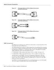
.../TIA-449, EIA-530 refers to the DTE and DCE interfaces and, as either DTE (DB-15 plug) or DCE (DB-15 receptacle). Although the specification recommends a maximum speed of the EIA-530 adapter cable is used in DTE mode only. The network end of 2 Mbps, EIA-530 is a standard ...DB-25 plug commonly used for EIA/TIA-232 connections. X.21 relocates some of the logic functions to the electrical specifications of the 37-pin connectors used for EIA/TIA-449. Figure 2-16 X.21 Adapter Cable Connectors, Network End 8 1 15 9 DTE DCE H1346a EIA-530 ...
.../TIA-449, EIA-530 refers to the DTE and DCE interfaces and, as either DTE (DB-15 plug) or DCE (DB-15 receptacle). Although the specification recommends a maximum speed of the EIA-530 adapter cable is used in DTE mode only. The network end of 2 Mbps, EIA-530 is a standard ...DB-25 plug commonly used for EIA/TIA-232 connections. X.21 relocates some of the logic functions to the electrical specifications of the 37-pin connectors used for EIA/TIA-449. Figure 2-16 X.21 Adapter Cable Connectors, Network End 8 1 15 9 DTE DCE H1346a EIA-530 ...

Hardware Maintenance Manual
Page 43
... configuration file, then dte-invert-timing must be manually changed. Network Connection Considerations If the network processor module is not configured. See the appendix "Cabling Specifications." An error message will be generated if there is a mismatch between the cable and the software configuration of the dte-invert-timing command must be...
... configuration file, then dte-invert-timing must be manually changed. Network Connection Considerations If the network processor module is not configured. See the appendix "Cabling Specifications." An error message will be generated if there is a mismatch between the cable and the software configuration of the dte-invert-timing command must be...
Hardware Maintenance Manual
Page 52
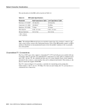
...(10 m) 32.8' (10 m) 1. If the BRI module connects to 24 virtual channels. kHz = kilohertz. 2. Network Connection Considerations The specifications for transmitting and receiving data bidirectionally at the T1 rate of 1.544 Mbps. On the CT1, the controller provides up to ISDN interfaces which... interfaces will occasionally lose some packets. This interface is presented to a channel service unit (CSU). Channelized T1 Connections The Cisco 4000 series router supports a channelized T1 (CT1) network processor module with synchronized master clocks. For wide-area networking, the...
...(10 m) 32.8' (10 m) 1. If the BRI module connects to 24 virtual channels. kHz = kilohertz. 2. Network Connection Considerations The specifications for transmitting and receiving data bidirectionally at the T1 rate of 1.544 Mbps. On the CT1, the controller provides up to ISDN interfaces which... interfaces will occasionally lose some packets. This interface is presented to a channel service unit (CSU). Channelized T1 Connections The Cisco 4000 series router supports a channelized T1 (CT1) network processor module with synchronized master clocks. For wide-area networking, the...
Hardware Maintenance Manual
Page 53
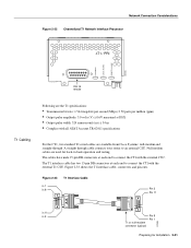
Null modem cables are available from Cisco Systems: null-modem and straight-through cable connects your router to an external CSU. Figure 2-33 shows the T1 interface cable, connectors and pin-outs. ... Considerations Figure 2-32 Channelized T1 Network Interface Processor cT1 / PRI LOOPBACK LOCAL ALARM REMOTE ALARM H3155 DB-15 female T1 Cabling Following are the T1 specifications: • Transmission bit rate: 1.544 megabits per second (Mbps) ± 50 parts per million (ppm) • Output pulse amplitude: 3.0 volts (V) ± 0.6V measured at DSX...
Null modem cables are available from Cisco Systems: null-modem and straight-through cable connects your router to an external CSU. Figure 2-33 shows the T1 interface cable, connectors and pin-outs. ... Considerations Figure 2-32 Channelized T1 Network Interface Processor cT1 / PRI LOOPBACK LOCAL ALARM REMOTE ALARM H3155 DB-15 female T1 Cabling Following are the T1 specifications: • Transmission bit rate: 1.544 megabits per second (Mbps) ± 50 parts per million (ppm) • Output pulse amplitude: 3.0 volts (V) ± 0.6V measured at DSX...

Hardware Maintenance Manual
Page 54
... Mbps. The figure shows the cable impedance set to a channel service unit (CSU). Jumper J2 (see G.703 / Section 6.3 (CCITT specification) • Jitter attenuation starting at the E1 rate of jumpers J1, J3, J4, J5, and J7. For wide-area networking, the... which meets or exceeds G.823 for a remote site. The CE1, shown in the G.703 specification. LOOPBACK LOCAL ALARM REMOTE ALARM H3154 Network Connection Considerations Channelized E1 Connections The Cisco 4000 series router supports a channelized E1 (CE1) network processor module with capacitive coupling between the receive...
... Mbps. The figure shows the cable impedance set to a channel service unit (CSU). Jumper J2 (see G.703 / Section 6.3 (CCITT specification) • Jitter attenuation starting at the E1 rate of jumpers J1, J3, J4, J5, and J7. For wide-area networking, the... which meets or exceeds G.823 for a remote site. The CE1, shown in the G.703 specification. LOOPBACK LOCAL ALARM REMOTE ALARM H3154 Network Connection Considerations Channelized E1 Connections The Cisco 4000 series router supports a channelized E1 (CE1) network processor module with capacitive coupling between the receive...
Hardware Maintenance Manual
Page 56
An ATM processor module can be installed in a back-to ATM switching fabrics for a Cisco 4000 series router provides a user network interface (UNI) between the router and an ATM network. Network Connection Considerations Figure 2-37 E1 Interface Cable for 120-...-mode fiber optical-STS-3c or STM-1 (See Figure 2-40) All ATM interfaces are full-duplex. If the middle slot is not occupied by the specific physical layer). You must use this slot for the ATM NPM. 2-34 Cisco 4000 Series Hardware Installation and Maintenance
An ATM processor module can be installed in a back-to ATM switching fabrics for a Cisco 4000 series router provides a user network interface (UNI) between the router and an ATM network. Network Connection Considerations Figure 2-37 E1 Interface Cable for 120-...-mode fiber optical-STS-3c or STM-1 (See Figure 2-40) All ATM interfaces are full-duplex. If the middle slot is not occupied by the specific physical layer). You must use this slot for the ATM NPM. 2-34 Cisco 4000 Series Hardware Installation and Maintenance

Hardware Maintenance Manual
Page 58
... desktop mounting • Optional equipment (which might be emitted from CDRH FDDI. Inspecting the System Note The ATM processor module for the Cisco 4000 series router uses identical duplex SC connectors for shipping damage. If the final installation site is connected. Also, please complete and mail... container, check the packing list to tell the difference is the yellow laser warning label on the single-mode module's front panel, or the specific part number visible on the upper surface of all of the following items: • Router • 6-foot (1.8-meter) power cord •...
... desktop mounting • Optional equipment (which might be emitted from CDRH FDDI. Inspecting the System Note The ATM processor module for the Cisco 4000 series router uses identical duplex SC connectors for shipping damage. If the final installation site is connected. Also, please complete and mail... container, check the packing list to tell the difference is the yellow laser warning label on the single-mode module's front panel, or the specific part number visible on the upper surface of all of the following items: • Router • 6-foot (1.8-meter) power cord •...
Hardware Maintenance Manual
Page 61
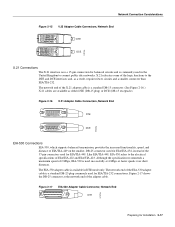
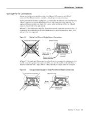
... to two connectors on the same port. For dual-port Ethernet modules (see Figure 3-3), connect either the Ethernet AUI connector or the 10BaseT connector on a specific Ethernet port, but not both on the right shows a supported connection with a single 10BaseT cable connecting to transceiver Installing the Router 3-3 the configuration on the...
... to two connectors on the same port. For dual-port Ethernet modules (see Figure 3-3), connect either the Ethernet AUI connector or the 10BaseT connector on a specific Ethernet port, but not both on the right shows a supported connection with a single 10BaseT cable connecting to transceiver Installing the Router 3-3 the configuration on the...