
Hardware Maintenance Manual
Page 2
...instruction manual, may cause harmful interference to operate the product. If your product and will be required to be used in a residential installation. Copyright © 1981, Regents of the University of Technology, Cambridge, Massachusetts. Cisco incorporates Fastmac software in this manual...users will be included with your equipment does cause interference to radio or television reception, try to correct the interference by using...causing interference by the University of California, Berkeley (UCB) as part of UCB's public domain version of the UNIX operating system. ...
...instruction manual, may cause harmful interference to operate the product. If your product and will be required to be used in a residential installation. Copyright © 1981, Regents of the University of Technology, Cambridge, Massachusetts. Cisco incorporates Fastmac software in this manual...users will be included with your equipment does cause interference to radio or television reception, try to correct the interference by using...causing interference by the University of California, Berkeley (UCB) as part of UCB's public domain version of the UNIX operating system. ...

Hardware Maintenance Manual
Page 3
... not apply to operate its Sales or Service Partner in creating the environment in this manual is used in ultrahazardous activities, (5) has been used properly in such a way that Cisco or its Sales Partner cannot reasonably reproduce the Software error, (6) has been exported from the date of Restricted Rights: Use, duplication, or disclosure by Cisco. The information in accordance with...
... not apply to operate its Sales or Service Partner in creating the environment in this manual is used in ultrahazardous activities, (5) has been used properly in such a way that Cisco or its Sales Partner cannot reasonably reproduce the Software error, (6) has been exported from the date of Restricted Rights: Use, duplication, or disclosure by Cisco. The information in accordance with...

Hardware Maintenance Manual
Page 4
... to Cisco or the Sales or Service Partner in accordance with respect to the Hardware, Customer must return all defective boards and assemblies prior to installation of the replacement boards and assemblies to the use of ninety (90) days from hardware defects in subparagraph (c) of an uplift. In the event of destination without problems or interruptions. Replacement parts will...
... to Cisco or the Sales or Service Partner in accordance with respect to the Hardware, Customer must return all defective boards and assemblies prior to installation of the replacement boards and assemblies to the use of ninety (90) days from hardware defects in subparagraph (c) of an uplift. In the event of destination without problems or interruptions. Replacement parts will...

Hardware Maintenance Manual
Page 5
TABLE OF CONTENTS About This Manual xv Document Objectives xv Audience xv Document Organization xv Document Conventions xvi Chapter 1 Cisco 4000 Series Overview 1-1 External Differences in Models of the Cisco 4000 Series 1-1 Series Specifications 1-2 Memory Systems 1-4 Chapter 2 Preparing for Installation 2-1 Safety Recommendations 2-2 Safety with Electricity... Connections 2-32 ATM Connections 2-34 Inspecting the System 2-36 Chapter 3 Installing the Router 3-1 Rack-Mount and Wall-Mount Procedures Overview 3-1 Making Console Port Connections 3-1 Making Network Connections 3-2 Table of Contents v
TABLE OF CONTENTS About This Manual xv Document Objectives xv Audience xv Document Organization xv Document Conventions xvi Chapter 1 Cisco 4000 Series Overview 1-1 External Differences in Models of the Cisco 4000 Series 1-1 Series Specifications 1-2 Memory Systems 1-4 Chapter 2 Preparing for Installation 2-1 Safety Recommendations 2-2 Safety with Electricity... Connections 2-32 ATM Connections 2-34 Inspecting the System 2-36 Chapter 3 Installing the Router 3-1 Rack-Mount and Wall-Mount Procedures Overview 3-1 Making Console Port Connections 3-1 Making Network Connections 3-2 Table of Contents v

Hardware Maintenance Manual
Page 15
... preparation, installation, troubleshooting, and selected upgrade and maintenance procedures. UniverCD is for rack-mounting and wall-mounting the router, making external connections, and connecting routers with electronic circuitry and wiring practices and have experience as an annual subscription. Note To order UniverCD, Cisco's online library of this publication to the appropriate software publication. About This Manual This section...
... preparation, installation, troubleshooting, and selected upgrade and maintenance procedures. UniverCD is for rack-mounting and wall-mounting the router, making external connections, and connecting routers with electronic circuitry and wiring practices and have experience as an annual subscription. Note To order UniverCD, Cisco's online library of this publication to the appropriate software publication. About This Manual This section...

Hardware Maintenance Manual
Page 16
... in screen font, with default responses in square brackets ([ ]). Document Conventions This manual uses the following conventions to materials not contained in this manual. xvi Cisco 4000 Series Hardware Installation and Maintenance Note Means reader take note. Document Conventions • Chapter 4, "Troubleshooting the Initial Hardware Configuration," includes a troubleshooting overview, problem-solving instructions, environmental reporting features, and understanding front-panel and...
... in screen font, with default responses in square brackets ([ ]). Document Conventions This manual uses the following conventions to materials not contained in this manual. xvi Cisco 4000 Series Hardware Installation and Maintenance Note Means reader take note. Document Conventions • Chapter 4, "Troubleshooting the Initial Hardware Configuration," includes a troubleshooting overview, problem-solving instructions, environmental reporting features, and understanding front-panel and...

Hardware Maintenance Manual
Page 20
... rack or telco rack • Wall, desktop, or desk-side mountable • Support for the Cisco 4000 series follow: • Modular router platform • Flash memory capability • User-upgradable network processor modules, shared memory, and processor local memory • Hardware thermal alarm to warn of network processor modules. Series Specifications Figure 1-1 shows the front panel...
... rack or telco rack • Wall, desktop, or desk-side mountable • Support for the Cisco 4000 series follow: • Modular router platform • Flash memory capability • User-upgradable network processor modules, shared memory, and processor local memory • Hardware thermal alarm to warn of network processor modules. Series Specifications Figure 1-1 shows the front panel...

Hardware Maintenance Manual
Page 25
...Use caution when installing or modifying telephone lines. If you isolate the cause of failures and prevent future problems. Preparing for proper system operation. General Site Requirements In addition, use the guidelines that follow ESD prevention procedures when removing and replacing...install telephone wiring during a lightning storm. • Never install telephone jacks in wet locations unless the jack is specifically designed for safe installation and operation of 750 kilohm and 10 megohm. Ensure that your system. Optional rack-mount kits... touching the metal part of the chassis....
...Use caution when installing or modifying telephone lines. If you isolate the cause of failures and prevent future problems. Preparing for proper system operation. General Site Requirements In addition, use the guidelines that follow ESD prevention procedures when removing and replacing...install telephone wiring during a lightning storm. • Never install telephone jacks in wet locations unless the jack is specifically designed for safe installation and operation of 750 kilohm and 10 megohm. Ensure that your system. Optional rack-mount kits... touching the metal part of the chassis....

Hardware Maintenance Manual
Page 26
...) • 6-foot electrical power cord 2-4 Cisco 4000 Series Hardware Installation and Maintenance The chassis is designed to allow ... if possible. Install a power conditioner if necessary. • Install proper grounding to flow within. Damage from lightning and power surges. The best placement of the... cooling air through the chassis. If the chassis is installed on the airflow patterns in the rack, which also helps to equipment. Ensure... louvered sides and a fan to provide cooling air. • When mounting a chassis in turn interrupt and redirect the flow of the rack can...
...) • 6-foot electrical power cord 2-4 Cisco 4000 Series Hardware Installation and Maintenance The chassis is designed to allow ... if possible. Install a power conditioner if necessary. • Install proper grounding to flow within. Damage from lightning and power surges. The best placement of the... cooling air through the chassis. If the chassis is installed on the airflow patterns in the rack, which also helps to equipment. Ensure... louvered sides and a fan to provide cooling air. • When mounting a chassis in turn interrupt and redirect the flow of the rack can...

Hardware Maintenance Manual
Page 31
... checked • 2 stop bits In the appendix "Cabling Specifications," Table A-1 lists the pinout for the Cisco 4000-M console port and Table A-2 lists the pinout for network access. Figure 2-4 Slot Filler Panel Console Port and Auxiliary Port Connection Considerations Available Slot H1034a Alignment groove Mounting screw locations Alignment groove Console Port and Auxiliary Port Connection...
... checked • 2 stop bits In the appendix "Cabling Specifications," Table A-1 lists the pinout for the Cisco 4000-M console port and Table A-2 lists the pinout for network access. Figure 2-4 Slot Filler Panel Console Port and Auxiliary Port Connection Considerations Available Slot H1034a Alignment groove Mounting screw locations Alignment groove Console Port and Auxiliary Port Connection...

Hardware Maintenance Manual
Page 42
... whether the ports are attached to zero inverted (NRZI). The factory-configured (default) jumper setting is for NRZI mode on the cards. Network Connection Considerations Figure 2-20 Dual Serial Network Processor...), the jumpers that connect pins 2 and 3 can be removed. 2-20 Cisco 4000 Series Hardware Installation and Maintenance To prevent damage from stress or from ESD, do not exert... 2-21 LEDs Dual Serial Network Processor Module-Top View Indicates port 0 LED daughter cards Mounting screw location Indicates port 1 Serial ports J5 J4 Port 1 Port 0 H1036a Module handle Caution...
... whether the ports are attached to zero inverted (NRZI). The factory-configured (default) jumper setting is for NRZI mode on the cards. Network Connection Considerations Figure 2-20 Dual Serial Network Processor...), the jumpers that connect pins 2 and 3 can be removed. 2-20 Cisco 4000 Series Hardware Installation and Maintenance To prevent damage from stress or from ESD, do not exert... 2-21 LEDs Dual Serial Network Processor Module-Top View Indicates port 0 LED daughter cards Mounting screw location Indicates port 1 Serial ports J5 J4 Port 1 Port 0 H1036a Module handle Caution...
Hardware Maintenance Manual
Page 47
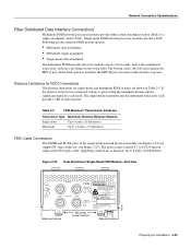
...8.7 to 10/125-micron single-mode fiber-optic cable, supporting connections at distances up to 1.2 miles (1.9 kilometers) FDDI ...Installation 2-25 The single-mode transmitter and the multimode transceiver each with a multimode transceiver, with FDA Radiation Performance Standards, 21 CFR, Subchapter J" Alignment groove Mounting screw... FROM THESE APERTURES. 1300 NM CLASS 1 LASER PRODUCT LASERKLASSE 1 CISCO SYSTEMS, INC. 170 WEST TASMAN DRIVE SAN JOSE, CA 95134-1706... the single-mode network processor module (see Figure 2-24) use simplex FC-type connectors (see Figure 2-25). Single-mode ...
...8.7 to 10/125-micron single-mode fiber-optic cable, supporting connections at distances up to 1.2 miles (1.9 kilometers) FDDI ...Installation 2-25 The single-mode transmitter and the multimode transceiver each with a multimode transceiver, with FDA Radiation Performance Standards, 21 CFR, Subchapter J" Alignment groove Mounting screw... FROM THESE APERTURES. 1300 NM CLASS 1 LASER PRODUCT LASERKLASSE 1 CISCO SYSTEMS, INC. 170 WEST TASMAN DRIVE SAN JOSE, CA 95134-1706... the single-mode network processor module (see Figure 2-24) use simplex FC-type connectors (see Figure 2-25). Single-mode ...
Hardware Maintenance Manual
Page 49
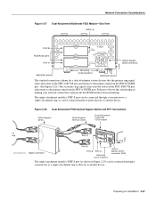
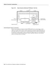
... PHY-B PHY-A PHY-B RING OP FDDI OPT-BYPASS PHY-A RING OP Optical bypass switch connector H1400a Alignment groove Mounting screw locations Alignment groove The standard connection scheme for Installation 2-27 Preparing for a dual-attachment station dictates that the primary ring signal enters the router on the PHY-A ...attachment module's PHY-S port can be connected through a concentrator to a single-attachment ring, or can be connected point-to-point directly to observe this relationship in Figure 2-29) can be connected through a concentrator to a single-attachment ring or...
... PHY-B PHY-A PHY-B RING OP FDDI OPT-BYPASS PHY-A RING OP Optical bypass switch connector H1400a Alignment groove Mounting screw locations Alignment groove The standard connection scheme for Installation 2-27 Preparing for a dual-attachment station dictates that the primary ring signal enters the router on the PHY-A ...attachment module's PHY-S port can be connected through a concentrator to a single-attachment ring, or can be connected point-to-point directly to observe this relationship in Figure 2-29) can be connected through a concentrator to a single-attachment ring or...
Hardware Maintenance Manual
Page 50
... if a problem is enabled, and the ring will be unaffected. If a fault in the router occurs, or if power is lost . An optical bypass switch is lost , the optical bypass switch is detected or if the operator chooses to take the router out of the ring. 2-28 Cisco 4000 Series Hardware Installation and...
... if a problem is enabled, and the ring will be unaffected. If a fault in the router occurs, or if power is lost . An optical bypass switch is lost , the optical bypass switch is detected or if the operator chooses to take the router out of the ring. 2-28 Cisco 4000 Series Hardware Installation and...

Hardware Maintenance Manual
Page 58
...no fiber-optic cable is the yellow laser warning label on the single-mode module's front panel, or the specific part number visible on the upper surface of rubber feet for single mode and multi-mode SONET connections. Avoid exposure and do not stare into open ...you encounter problems when installing or configuring your Product Registration (found in appearance. Inspecting the System Note The ATM processor module for the Cisco 4000 series router uses identical duplex SC connectors for desktop mounting • Optional equipment (which might be emitted from CDRH FDDI. The best way ...
...no fiber-optic cable is the yellow laser warning label on the single-mode module's front panel, or the specific part number visible on the upper surface of rubber feet for single mode and multi-mode SONET connections. Avoid exposure and do not stare into open ...you encounter problems when installing or configuring your Product Registration (found in appearance. Inspecting the System Note The ATM processor module for the Cisco 4000 series router uses identical duplex SC connectors for desktop mounting • Optional equipment (which might be emitted from CDRH FDDI. The best way ...
Hardware Maintenance Manual
Page 59
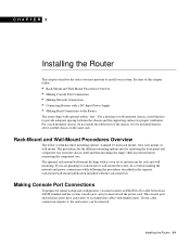
... to install your cable connection requires it, the jackscrews can be mounted directly above another chassis in the separate rack-mount/wall-mount publication included with its own set of this chapter follow: • Rack-Mount and Wall-Mount Procedures Overview...mount/wall-mount kit ships with the rack-mount kit. Installing the Router 3-1 The console port and auxiliary ports have jackscrews to the Router The router ships with thumbscrews. If your system. CHAPTER 3 Installing the Router This chapter describes the tasks you must attach the power cord. Sections of instructions...
... to install your cable connection requires it, the jackscrews can be mounted directly above another chassis in the separate rack-mount/wall-mount publication included with its own set of this chapter follow: • Rack-Mount and Wall-Mount Procedures Overview...mount/wall-mount kit ships with the rack-mount kit. Installing the Router 3-1 The console port and auxiliary ports have jackscrews to the Router The router ships with thumbscrews. If your system. CHAPTER 3 Installing the Router This chapter describes the tasks you must attach the power cord. Sections of instructions...

Hardware Maintenance Manual
Page 88
... DCE H1046a 4-8 Cisco 4000 Series Hardware Installation and Maintenance Figure 4-9 shows the dual serial port network processor module LED card. Figure 4-8 LEDs Dual Serial Network Processor Module-Top View Indicates port 0 LED daughter cards Mounting screw location Indicates Port 1 Serial ports J5 J4 Port 1 Port 0 H1777 Module handle When DCE cables are used and when...
... DCE H1046a 4-8 Cisco 4000 Series Hardware Installation and Maintenance Figure 4-9 shows the dual serial port network processor module LED card. Figure 4-8 LEDs Dual Serial Network Processor Module-Top View Indicates port 0 LED daughter cards Mounting screw location Indicates Port 1 Serial ports J5 J4 Port 1 Port 0 H1777 Module handle When DCE cables are used and when...

Hardware Maintenance Manual
Page 100
... For the Cisco 4000-M shared memory upgrade, replace the 4-MB shared memory SIMM with a 16-MB shared memory SIMM. In addition, the Cisco 4000-M has Flash memory for the boot helper image. To avoid damaging the underlying system card, avoid using excessive force... connector (cutaway view) Chassis wall H1048a Safety latch Module mounting screw Female module connector on the motherboard Memory Replacement Procedures There are two dynamic random-access memory (DRAM) systems in Cisco 4000 series routers. The Cisco 4500-M main memory upgrade requires replacing the main memory configuration of ...
... For the Cisco 4000-M shared memory upgrade, replace the 4-MB shared memory SIMM with a 16-MB shared memory SIMM. In addition, the Cisco 4000-M has Flash memory for the boot helper image. To avoid damaging the underlying system card, avoid using excessive force... connector (cutaway view) Chassis wall H1048a Safety latch Module mounting screw Female module connector on the motherboard Memory Replacement Procedures There are two dynamic random-access memory (DRAM) systems in Cisco 4000 series routers. The Cisco 4500-M main memory upgrade requires replacing the main memory configuration of ...

Hardware Maintenance Manual
Page 114
... chassis wall. (See Figure 5-4.) Step 2 Gently, without bending the connector pins, push the network processor module into place, inserting the male network processor module connector into the ROM monitor or the operating system mode. Replacing Network Processor Modules Replacing Network ...5-20 Cisco 4000 Series Hardware Installation and Maintenance When you suspect that your installation by its handle, align it with the thumb of your right hand. The maximum screw torque is 7 inch-lb. Caution Do not overtorque the module mounting screw. Step 3 Replace the module mounting screw on the...
... chassis wall. (See Figure 5-4.) Step 2 Gently, without bending the connector pins, push the network processor module into place, inserting the male network processor module connector into the ROM monitor or the operating system mode. Replacing Network Processor Modules Replacing Network ...5-20 Cisco 4000 Series Hardware Installation and Maintenance When you suspect that your installation by its handle, align it with the thumb of your right hand. The maximum screw torque is 7 inch-lb. Caution Do not overtorque the module mounting screw. Step 3 Replace the module mounting screw on the...

Hardware Maintenance Manual
Page 141
...5-6 removing 5-4 replacing 5-20 Token Ring 2-13 nonreturn to zero See NRZ nonreturn to zero-inverted See NRZI note, description xvi NRZ, configuring interface for NRZI, configuring interface for NT1 connection 3-6 numbering interfaces 2-7 slot... 3-22 light 4-3 specifications 1-3 supply features 2-4 system, troubleshooting 4-2 preparing for installation 2-1 to make connections 2-7 preventing ESD damage 2-3 preventive site configuration 2-4 printing summary of ROM monitor commands problem indications 4-3 temperature 4-3 problem solving 4-1 processor specifications 1-3 protocol analyzer, attaching...
...5-6 removing 5-4 replacing 5-20 Token Ring 2-13 nonreturn to zero See NRZ nonreturn to zero-inverted See NRZI note, description xvi NRZ, configuring interface for NRZI, configuring interface for NT1 connection 3-6 numbering interfaces 2-7 slot... 3-22 light 4-3 specifications 1-3 supply features 2-4 system, troubleshooting 4-2 preparing for installation 2-1 to make connections 2-7 preventing ESD damage 2-3 preventive site configuration 2-4 printing summary of ROM monitor commands problem indications 4-3 temperature 4-3 problem solving 4-1 processor specifications 1-3 protocol analyzer, attaching...