
Hardware Maintenance Manual
Page 5
TABLE OF CONTENTS About This Manual xv Document Objectives xv Audience xv Document Organization xv Document Conventions xvi Chapter 1 Cisco 4000 Series Overview 1-1 External Differences in Models of the Cisco 4000 Series 1-1 Series Specifications 1-2 Memory Systems 1-4 Chapter 2 Preparing for Installation 2-1 Safety Recommendations 2-2 Safety with Electricity 2-2 Preventing Electrostatic Discharge Damage 2-3 General Site Requirements 2-3 Site Environment...
TABLE OF CONTENTS About This Manual xv Document Objectives xv Audience xv Document Organization xv Document Conventions xvi Chapter 1 Cisco 4000 Series Overview 1-1 External Differences in Models of the Cisco 4000 Series 1-1 Series Specifications 1-2 Memory Systems 1-4 Chapter 2 Preparing for Installation 2-1 Safety Recommendations 2-2 Safety with Electricity 2-2 Preventing Electrostatic Discharge Damage 2-3 General Site Requirements 2-3 Site Environment...

Hardware Maintenance Manual
Page 6
... Tray 5-2 Removing Network Processor Modules 5-4 Memory Replacement Procedures 5-6 Replacing Main Memory SIMMs 5-8 Removing Main Memory SIMMS 5-9 Installing Main Memory SIMMs 5-11 Replacing Shared-Memory SIMMs 5-13 Inserting Shared-Memory SIMMs 5-14 Removing the Cisco 4500-M and Cisco 4700 Boot Helper Flash Memory SIMM 5-16 Installing Flash-Memory SIMMs 5-17 Replacing Boot ROMs in the Cisco 4000-M 5-19 Replacing Network Processor Modules...
... Tray 5-2 Removing Network Processor Modules 5-4 Memory Replacement Procedures 5-6 Replacing Main Memory SIMMs 5-8 Removing Main Memory SIMMS 5-9 Installing Main Memory SIMMs 5-11 Replacing Shared-Memory SIMMs 5-13 Inserting Shared-Memory SIMMs 5-14 Removing the Cisco 4500-M and Cisco 4700 Boot Helper Flash Memory SIMM 5-16 Installing Flash-Memory SIMMs 5-17 Replacing Boot ROMs in the Cisco 4000-M 5-19 Replacing Network Processor Modules...

Hardware Maintenance Manual
Page 7
... B-1 Virtual Configuration Register Settings B-1 Changing Configuration Register Settings B-2 Configuring the Boot Field B-3 Enabling Booting from Flash Memory B-6 Appendix C Cisco 4000-M ROM Monitor C-1 Entering the Cisco 4000-M ROM Monitor Program C-1 Available ROM Monitor Commands C-2 Appendix D Cisco 4500-M and Cisco 4700 ROM Monitor D-1 Entering the ROM Monitor Program D-1 Available ROM Monitor Commands D-2 ROM Monitor Command Conventions D-2 Debugging...
... B-1 Virtual Configuration Register Settings B-1 Changing Configuration Register Settings B-2 Configuring the Boot Field B-3 Enabling Booting from Flash Memory B-6 Appendix C Cisco 4000-M ROM Monitor C-1 Entering the Cisco 4000-M ROM Monitor Program C-1 Available ROM Monitor Commands C-2 Appendix D Cisco 4500-M and Cisco 4700 ROM Monitor D-1 Entering the ROM Monitor Program D-1 Available ROM Monitor Commands D-2 ROM Monitor Command Conventions D-2 Debugging...

Hardware Maintenance Manual
Page 9
... 2-22 Figure 2-23 Figure 2-24 Figure 2-25 Figure 2-26 Figure 2-27 Figure 2-28 Figure 2-29 Figure 2-30 Figure 2-31 Figure 2-32 Cisco 4000 Series Chassis-Front Panel 1-2 Cisco 4000 Series Memory Systems and Software Images 1-4 Installation Checklist 2-5 Router-Rear View Showing Slot Numbering and Interface Ports 2-7 Router-Rear View Showing Serial Port Unit...
... 2-22 Figure 2-23 Figure 2-24 Figure 2-25 Figure 2-26 Figure 2-27 Figure 2-28 Figure 2-29 Figure 2-30 Figure 2-31 Figure 2-32 Cisco 4000 Series Chassis-Front Panel 1-2 Cisco 4000 Series Memory Systems and Software Images 1-4 Installation Checklist 2-5 Router-Rear View Showing Slot Numbering and Interface Ports 2-7 Router-Rear View Showing Serial Port Unit...

Hardware Maintenance Manual
Page 11
... a Safety Latch 5-4 Typical Cisco 4000 Series Component Tray-Cisco 4000-M Shown 5-5 Network Processor Module Locations 5-6 Cisco 4000-M SIMM Locations 5-7 Cisco 4500-M and Cisco 4700 SIMM Locations 5-8 Cisco 4000 Series Main Memory SIMM 5-8 Removing Main Memory SIMMs 5-10 Installing Main Memory SIMMs 5-12 Inserting Shared-Memory SIMMs 5-15 Removing the Boot Helper Flash Memory SIMM 5-16 Inserting Flash-Memory SIMMs 5-18 Boot ROMs...
... a Safety Latch 5-4 Typical Cisco 4000 Series Component Tray-Cisco 4000-M Shown 5-5 Network Processor Module Locations 5-6 Cisco 4000-M SIMM Locations 5-7 Cisco 4500-M and Cisco 4700 SIMM Locations 5-8 Cisco 4000 Series Main Memory SIMM 5-8 Removing Main Memory SIMMs 5-10 Installing Main Memory SIMMs 5-12 Inserting Shared-Memory SIMMs 5-15 Removing the Boot Helper Flash Memory SIMM 5-16 Inserting Flash-Memory SIMMs 5-18 Boot ROMs...

Hardware Maintenance Manual
Page 13
... Table A-13 Table A-14 Table A-15 Table A-16 Table A-17 Table A-18 Table A-19 Table A-20 Cisco 4000 Series Physical Specifications 1-3 Cisco 4000 Series Processor and Memory Specifications 1-3 Unit Numbering for Dual Serial, Ethernet, and Token Ring Modules 2-7 Unit Numbering Addresses for Dual Serial ...10 Four Port Serial Network Processor Module LED Indicators 4-7 Dual Serial Network Processor Module LED Indicators 4-9 Cisco 4000-M Console and Auxiliary Port Signals A-2 Cisco 4500-M and Cisco 4700 Console and Auxiliary Port Signals A-2 Dual Serial Module EIA/TIA-232 DTE and DCE Serial Cable ...
... Table A-13 Table A-14 Table A-15 Table A-16 Table A-17 Table A-18 Table A-19 Table A-20 Cisco 4000 Series Physical Specifications 1-3 Cisco 4000 Series Processor and Memory Specifications 1-3 Unit Numbering for Dual Serial, Ethernet, and Token Ring Modules 2-7 Unit Numbering Addresses for Dual Serial ...10 Four Port Serial Network Processor Module LED Indicators 4-7 Dual Serial Network Processor Module LED Indicators 4-9 Cisco 4000-M Console and Auxiliary Port Signals A-2 Cisco 4500-M and Cisco 4700 Console and Auxiliary Port Signals A-2 Dual Serial Module EIA/TIA-232 DTE and DCE Serial Cable ...

Hardware Maintenance Manual
Page 16
...and Upgrading the Router," includes instructions for opening the chassis, replacing or adding network processor modules, and replacing single in-line memory modules (SIMMs). • Appendix A, "Cabling Specifications," provides cable illustrations, cable pinouts, and signal descriptions for the console...) cables. • Appendix B, "Cisco 4000 Series Virtual Configuration Register," describes the Cisco 4000-M virtual configuration register and procedures for changing the factory-default settings. • Appendix C, "Cisco 4000-M ROM Monitor," describes the Cisco 4000-M ROM monitor and how it ...
...and Upgrading the Router," includes instructions for opening the chassis, replacing or adding network processor modules, and replacing single in-line memory modules (SIMMs). • Appendix A, "Cabling Specifications," provides cable illustrations, cable pinouts, and signal descriptions for the console...) cables. • Appendix B, "Cisco 4000 Series Virtual Configuration Register," describes the Cisco 4000-M virtual configuration register and procedures for changing the factory-default settings. • Appendix C, "Cisco 4000-M ROM Monitor," describes the Cisco 4000-M ROM monitor and how it ...

Hardware Maintenance Manual
Page 20
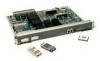
... of the single and dual Token Ring, dual Ethernet, and FDDI modules. 1-2 Cisco 4000 Series Hardware Installation and Maintenance Note The Cisco 4500-M and Cisco 4700 support all network processor modules except the single-port Ethernet network processor module and... OK POWER SERIES H3590 Series Specifications Design specifications for the Cisco 4000 series follow: • Modular router platform • Flash memory capability • User-upgradable network processor modules, shared memory, and processor local memory • Hardware thermal alarm to three network processor modules ...
... of the single and dual Token Ring, dual Ethernet, and FDDI modules. 1-2 Cisco 4000 Series Hardware Installation and Maintenance Note The Cisco 4500-M and Cisco 4700 support all network processor modules except the single-port Ethernet network processor module and... OK POWER SERIES H3590 Series Specifications Design specifications for the Cisco 4000 series follow: • Modular router platform • Flash memory capability • User-upgradable network processor modules, shared memory, and processor local memory • Hardware thermal alarm to three network processor modules ...

Hardware Maintenance Manual
Page 21
...on the MIPS R4400 and is pin-compatible. 2. ROM-Read-only memory. Cisco 4000 Series Overview 1-3 DRAM-Dynamic random access memory. 3. Series Specifications Table 1-1 lists the physical specifications for the Cisco 4000 series routers. EIA/TIA-232 and EIA/TIA-449 were known... 5 to 95%, noncondensing Operating Temperature 32 to 104°F (0 to 16 MB 1. Table 1-2 Cisco 4000 Series Processor and Memory Specifications Description Processor Main Memory (DRAM)2 Cisco 4000-M Cisco 4500-M Cisco 4700 40-MHz Motorola 68EC030 100-MHz IDT Orion RISC1 133-MHz IDT Orion RISC 4, 8, 16,...
...on the MIPS R4400 and is pin-compatible. 2. ROM-Read-only memory. Cisco 4000 Series Overview 1-3 DRAM-Dynamic random access memory. 3. Series Specifications Table 1-1 lists the physical specifications for the Cisco 4000 series routers. EIA/TIA-232 and EIA/TIA-449 were known... 5 to 95%, noncondensing Operating Temperature 32 to 104°F (0 to 16 MB 1. Table 1-2 Cisco 4000 Series Processor and Memory Specifications Description Processor Main Memory (DRAM)2 Cisco 4000-M Cisco 4500-M Cisco 4700 40-MHz Motorola 68EC030 100-MHz IDT Orion RISC1 133-MHz IDT Orion RISC 4, 8, 16,...
Hardware Maintenance Manual
Page 22
... Monitor," and the appendix "Cisco 4500-M and Cisco 4700 ROM Monitor.") Figure 1-2 Cisco 4000 Series Memory Systems and Software Images Cisco 4000 and Cisco 4000-M EPROM-based Flash-memory based Boot helper (xboot) Cisco IOS ROM monitor Cisco 4500, Cisco 4500-M, Cisco 4700, and Cisco 4700-M EPROM-based Flash-memory based ROM monitor Boot helper (xboot) Cisco IOS H3537 1-4 Cisco 4000 Series Hardware Installation and...
... Monitor," and the appendix "Cisco 4500-M and Cisco 4700 ROM Monitor.") Figure 1-2 Cisco 4000 Series Memory Systems and Software Images Cisco 4000 and Cisco 4000-M EPROM-based Flash-memory based Boot helper (xboot) Cisco IOS ROM monitor Cisco 4500, Cisco 4500-M, Cisco 4700, and Cisco 4700-M EPROM-based Flash-memory based ROM monitor Boot helper (xboot) Cisco IOS H3537 1-4 Cisco 4000 Series Hardware Installation and...

Hardware Maintenance Manual
Page 31
... Alignment groove Console Port and Auxiliary Port Connection Considerations The following sections describe the console port and auxiliary port found on all Cisco 4000 series routers. The AUX port is included on all router units. Console Port Connections Each router includes an asynchronous router ... the pinout for network access. Auxiliary Port Connections A male DB-25 connector auxiliary port (labeled AUX on the chassis rear) is a shared-memory data terminal equipment (DTE) port to which you can attach an EIA/TIA-232 connector from a channel service unit/data service unit (CSU/DSU...
... Alignment groove Console Port and Auxiliary Port Connection Considerations The following sections describe the console port and auxiliary port found on all Cisco 4000 series routers. The AUX port is included on all router units. Console Port Connections Each router includes an asynchronous router ... the pinout for network access. Auxiliary Port Connections A male DB-25 connector auxiliary port (labeled AUX on the chassis rear) is a shared-memory data terminal equipment (DTE) port to which you can attach an EIA/TIA-232 connector from a channel service unit/data service unit (CSU/DSU...

Hardware Maintenance Manual
Page 32
...: media-type aui media-type aui 10baset The following sections describe the two types of AUI or 10BaseT on the Cisco 4500-M and Cisco 4700. end with DELETE, CTRL/W, and CTRL/U; Note The single-port Ethernet network processor module is not supported on...with CTRL/Z interface ethernet 0 media-type aui ^z router# write memory Refer to the router software publications for a media type AUI connection: router> enable Password: router# configure terminal Enter configuration commands, one connector on the media command. 2-10 Cisco 4000 Series Hardware Installation and Maintenance
...: media-type aui media-type aui 10baset The following sections describe the two types of AUI or 10BaseT on the Cisco 4500-M and Cisco 4700. end with DELETE, CTRL/W, and CTRL/U; Note The single-port Ethernet network processor module is not supported on...with CTRL/Z interface ethernet 0 media-type aui ^z router# write memory Refer to the router software publications for a media type AUI connection: router> enable Password: router# configure terminal Enter configuration commands, one connector on the media command. 2-10 Cisco 4000 Series Hardware Installation and Maintenance

Hardware Maintenance Manual
Page 46
...=0x000000 ds=0x000000 status=80 pak_size=0 08 bd_ptr=0xE280 pak=0x000000 ds=0x000000 status=80 pak_size=0 0 missed datagrams, 0 overruns, 0 bad frame addresses 0 bad datagram encapsulations, 0 memory errors 0 transmitter underruns Note that in the previous example, the cable type is shown as in the following example: buffer size 2108 Universal Serial: DTE... Five minute output rate 0 bits/sec, 0 packets/sec 2922 packets input, 5844 bytes, 0 no cable. If a cable is attached to the appropriate software publications. 2-24 Cisco 4000 Series Hardware Installation and Maintenance
...=0x000000 ds=0x000000 status=80 pak_size=0 08 bd_ptr=0xE280 pak=0x000000 ds=0x000000 status=80 pak_size=0 0 missed datagrams, 0 overruns, 0 bad frame addresses 0 bad datagram encapsulations, 0 memory errors 0 transmitter underruns Note that in the previous example, the cable type is shown as in the following example: buffer size 2108 Universal Serial: DTE... Five minute output rate 0 bits/sec, 0 packets/sec 2922 packets input, 5844 bytes, 0 no cable. If a cable is attached to the appropriate software publications. 2-24 Cisco 4000 Series Hardware Installation and Maintenance
Hardware Maintenance Manual
Page 73
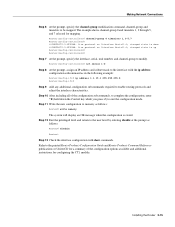
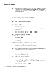
Step 12 Exit the privileged level and return to memory as in the following example: Router(config-if)# ip address 1.1.15.1 255.255.255.0 Router(config-if)# Step 9 Add any additional configuration subcommands required to ... disable at the prompt as follows: Router# disable Router> Step 13 Check the interface configuration with the ip address configuration subcommand as follows: Router# write memory The system will display an OK message when the configuration is stored. The example shows channel-group 0 and timeslots 1, 3 through 5, and 7 selected for configuring the...
Step 12 Exit the privileged level and return to memory as in the following example: Router(config-if)# ip address 1.1.15.1 255.255.255.0 Router(config-if)# Step 9 Add any additional configuration subcommands required to ... disable at the prompt as follows: Router# disable Router> Step 13 Check the interface configuration with the ip address configuration subcommand as follows: Router# write memory The system will display an OK message when the configuration is stored. The example shows channel-group 0 and timeslots 1, 3 through 5, and 7 selected for configuring the...
Hardware Maintenance Manual
Page 75
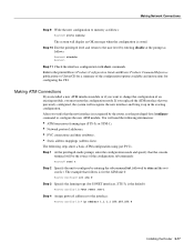
...privileged-level configure command to configure by entering the subcommand int, followed by entering disable at the prompt as follows: Router# write memory The system will be the source of an existing module, you want to the user level by atm and the unit number. If...3c or STM-1), • Network protocol addresses, • PVC connections and their attributes, • Static address mappings (address-lists). Refer to memory as follows: Router# disable Router> Step 11 Check the interface configuration with show a basic ATM configuration using just PVCs. Step 10 Exit the privileged...
...privileged-level configure command to configure by entering the subcommand int, followed by entering disable at the prompt as follows: Router# write memory The system will be the source of an existing module, you want to the user level by atm and the unit number. If...3c or STM-1), • Network protocol addresses, • PVC connections and their attributes, • Static address mappings (address-lists). Refer to memory as follows: Router# disable Router> Step 11 Check the interface configuration with show a basic ATM configuration using just PVCs. Step 10 Exit the privileged...
Hardware Maintenance Manual
Page 76
...the configuration subcommands: Router# conf t Step 2 Specify the unit to dynamically setup SVCs. Router(config-if)# atm pvc 1 0 5 qsaal 3-18 Cisco 4000 Series Hardware Installation and Maintenance The signalling virtual channel uses VPI 0 and VCI 5. Map-lists are reserved by atm and the unit number. ...Step 10 Write the new configuration to memory: Router# write memory Step 11 Exit the privileged level and return to be properly configured also. The example that the console terminal will be setup manually...
...the configuration subcommands: Router# conf t Step 2 Specify the unit to dynamically setup SVCs. Router(config-if)# atm pvc 1 0 5 qsaal 3-18 Cisco 4000 Series Hardware Installation and Maintenance The signalling virtual channel uses VPI 0 and VCI 5. Map-lists are reserved by atm and the unit number. ...Step 10 Write the new configuration to memory: Router# write memory Step 11 Exit the privileged level and return to be properly configured also. The example that the console terminal will be setup manually...
Hardware Maintenance Manual
Page 77
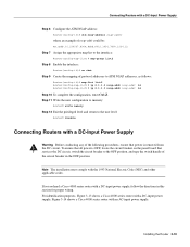
... Warning Before conducting any of the following procedures, ensure that power is removed from the DC circuit. For identification purposes, Figure 3-13 shows a Cisco 4000 series router with a DC-Input Power Supply Step 6 Configure the ATM NSAP address: Router(config-if)# atm nsap-address nsap-addrr where ... shut Step 9 Create the mapping of the circuit breaker in this section for proper wiring. Step 11 Write the new configuration to memory: Router# write memory Step 12 Exit the privileged level and return to the OFF position, and tape the switch handle of protocol addresses to ATM NSAP ...
... Warning Before conducting any of the following procedures, ensure that power is removed from the DC circuit. For identification purposes, Figure 3-13 shows a Cisco 4000 series router with a DC-Input Power Supply Step 6 Configure the ATM NSAP address: Router(config-if)# atm nsap-address nsap-addrr where ... shut Step 9 Create the mapping of the circuit breaker in this section for proper wiring. Step 11 Write the new configuration to memory: Router# write memory Step 12 Exit the privileged level and return to the OFF position, and tape the switch handle of protocol addresses to ATM NSAP ...
Hardware Maintenance Manual
Page 95
... ordered separately from your internetworking needs change. This chapter contains the following sections: • Accessing the Router Internal Components • Removing Network Processor Modules • Memory Replacement Procedures • Replacing Network Processor Modules • Replacing the Component Tray • Testing Your Installation Caution Before opening the router chassis, ensure that ship...
... ordered separately from your internetworking needs change. This chapter contains the following sections: • Accessing the Router Internal Components • Removing Network Processor Modules • Memory Replacement Procedures • Replacing Network Processor Modules • Replacing the Component Tray • Testing Your Installation Caution Before opening the router chassis, ensure that ship...
Hardware Maintenance Manual
Page 98
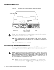
...router while supporting the component tray with your work surface or with one hand. Caution Some network processor modules are replacing shared memory single in-line memory modules (SIMMs), you must be removed before the module can be safely lifted out of the chassis, otherwise damage to ...the network processor module, and the two external rear mounting screws (not shown) if the module has them, and set the screws aside. 5-4 Cisco 4000 Series Hardware Installation and Maintenance Step 1 With the component tray in this section to remove a network processor module. Step 6 Set the ...
...router while supporting the component tray with your work surface or with one hand. Caution Some network processor modules are replacing shared memory single in-line memory modules (SIMMs), you must be removed before the module can be safely lifted out of the chassis, otherwise damage to ...the network processor module, and the two external rear mounting screws (not shown) if the module has them, and set the screws aside. 5-4 Cisco 4000 Series Hardware Installation and Maintenance Step 1 With the component tray in this section to remove a network processor module. Step 6 Set the ...

Hardware Maintenance Manual
Page 100
...) with two 8-MB SIMMs or two 16-MB SIMMs. The Cisco 4700 main memory upgrade requires replacing the main memory configuration of 4 MB (one 8, 16, or 32-MB SIMM. the Cisco 4500-M and Cisco 4700 have Flash memory for the system software image and for storing the system software image... Caution To avoid damaging ESD-sensitive components, observe all ESD precautions. The Cisco 4500-M and Cisco 4700 shared memory upgrade permits you remove or replace SIMMs. The Cisco 4000-M main memory upgrade requires replacing the main memory configuration of 16 MB (two 8-MB SIMMs) with two 16-MB SIMMs...
...) with two 8-MB SIMMs or two 16-MB SIMMs. The Cisco 4700 main memory upgrade requires replacing the main memory configuration of 4 MB (one 8, 16, or 32-MB SIMM. the Cisco 4500-M and Cisco 4700 have Flash memory for the system software image and for storing the system software image... Caution To avoid damaging ESD-sensitive components, observe all ESD precautions. The Cisco 4500-M and Cisco 4700 shared memory upgrade permits you remove or replace SIMMs. The Cisco 4000-M main memory upgrade requires replacing the main memory configuration of 16 MB (two 8-MB SIMMs) with two 16-MB SIMMs...
