
Hardware Maintenance Manual
Page 3
...refund the price of the hardware less depreciation calculated on a straight-line basis. All rights reserved. PLEASE READ THESE TERMS AND CONDITIONS CAREFULLY BEFORE USING THE SOFTWARE. BY USING THE SOFTWARE OF CISCO SYSTEMS, INC. Customer may make available such trade secrets or copyrighted...in ultrahazardous activities, (5) has been used properly in the event that the Software is subject to restrictions as authorized by Cisco and Bringing the power of internetworking to Customer the license fee for a remedy, Customer must report all copyright, confidentiality, and proprietary notices ...
...refund the price of the hardware less depreciation calculated on a straight-line basis. All rights reserved. PLEASE READ THESE TERMS AND CONDITIONS CAREFULLY BEFORE USING THE SOFTWARE. BY USING THE SOFTWARE OF CISCO SYSTEMS, INC. Customer may make available such trade secrets or copyrighted...in ultrahazardous activities, (5) has been used properly in the event that the Software is subject to restrictions as authorized by Cisco and Bringing the power of internetworking to Customer the license fee for a remedy, Customer must report all copyright, confidentiality, and proprietary notices ...

Hardware Maintenance Manual
Page 6
... Connections 3-11 Making T1 Connections 3-14 Making E1 Connections 3-16 Making ATM Connections 3-17 Connecting Routers with a DC-Input Power Supply 3-19 Wiring the DC-Input Power Supply 3-20 Making Final Connections to the Router 3-22 Chapter 4 Troubleshooting the Initial Hardware Configuration 4-1 Problem Solving 4-1 Troubleshooting ...Memory SIMMS 5-9 Installing Main Memory SIMMs 5-11 Replacing Shared-Memory SIMMs 5-13 Inserting Shared-Memory SIMMs 5-14 Removing the Cisco 4500-M and Cisco 4700 Boot Helper Flash Memory SIMM 5-16 Installing Flash-Memory SIMMs 5-17 Replacing Boot ROMs in the...
... Connections 3-11 Making T1 Connections 3-14 Making E1 Connections 3-16 Making ATM Connections 3-17 Connecting Routers with a DC-Input Power Supply 3-19 Wiring the DC-Input Power Supply 3-20 Making Final Connections to the Router 3-22 Chapter 4 Troubleshooting the Initial Hardware Configuration 4-1 Problem Solving 4-1 Troubleshooting ...Memory SIMMS 5-9 Installing Main Memory SIMMs 5-11 Replacing Shared-Memory SIMMs 5-13 Inserting Shared-Memory SIMMs 5-14 Removing the Cisco 4500-M and Cisco 4700 Boot Helper Flash Memory SIMM 5-16 Installing Flash-Memory SIMMs 5-17 Replacing Boot ROMs in the...

Hardware Maintenance Manual
Page 10
...Attachment Multimode FDDI Connections 3-12 Single-Mode Dual-Attachment FDDI Connections 3-13 Cisco 4000 Series DC-Input Power Supply-Rear View 3-20 Cisco 4000 Series AC-Input Power Supply-Rear View 3-20 DC-Input Power Supply Connections 3-21 Cisco 4000 Series-Front Panel Indicators 4-3 Dual-Port Ethernet Network Processor Module LEDs ... Processor Module Ports (DB-15) 4-6 Serial Port Labeled V2 4-7 Dual Serial Network Processor Module-Top View 4-8 Dual Serial Port LED Card-Side View 4-8 Dual-Attachment Single-Mode FDDI Module-End View 4-9 x Cisco 4000 Series Hardware Installation and Maintenance
...Attachment Multimode FDDI Connections 3-12 Single-Mode Dual-Attachment FDDI Connections 3-13 Cisco 4000 Series DC-Input Power Supply-Rear View 3-20 Cisco 4000 Series AC-Input Power Supply-Rear View 3-20 DC-Input Power Supply Connections 3-21 Cisco 4000 Series-Front Panel Indicators 4-3 Dual-Port Ethernet Network Processor Module LEDs ... Processor Module Ports (DB-15) 4-6 Serial Port Labeled V2 4-7 Dual Serial Network Processor Module-Top View 4-8 Dual Serial Port LED Card-Side View 4-8 Dual-Attachment Single-Mode FDDI Module-End View 4-9 x Cisco 4000 Series Hardware Installation and Maintenance

Hardware Maintenance Manual
Page 15
...on UniverCD, Cisco's online library of the Cisco 4000 Series...order UniverCD, contact your warranty package. Note To order UniverCD, Cisco's online library of the Cisco 4000 series features and physical specifications. • Chapter 2, "..., who should be more up to install and maintain the Cisco 4000-M, Cisco 4500-M, and the Cisco 4700. UniverCD is included in your local sales representative or... conventions of product information. Use this publication follow: • Chapter 1, "Cisco 4000 Series Overview," contains an overview of product information, or printed publications,...
...on UniverCD, Cisco's online library of the Cisco 4000 Series...order UniverCD, contact your warranty package. Note To order UniverCD, Cisco's online library of the Cisco 4000 series features and physical specifications. • Chapter 2, "..., who should be more up to install and maintain the Cisco 4000-M, Cisco 4500-M, and the Cisco 4700. UniverCD is included in your local sales representative or... conventions of product information. Use this publication follow: • Chapter 1, "Cisco 4000 Series Overview," contains an overview of product information, or printed publications,...

Hardware Maintenance Manual
Page 20
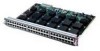
...the Channelized E1/ISDN PRI network interface module ((NP-CE1). Network processor modules can support two FDDI network processor modules. The Cisco 4500-M and Cisco 4700 can be placed in either a standard 19-inch rack or telco rack • Wall, desktop, or desk-side ...to warn of excessively high operating temperature • Rack-mountable in any desired combination. Figure 1-1 Cisco 4000 Series Chassis-Front Panel 1 DATA OK 2 DATA OK 3 DATA OK OK POWER SERIES H3590 Series Specifications Design specifications for up to three network processor modules at a time, including ...
...the Channelized E1/ISDN PRI network interface module ((NP-CE1). Network processor modules can support two FDDI network processor modules. The Cisco 4500-M and Cisco 4700 can be placed in either a standard 19-inch rack or telco rack • Wall, desktop, or desk-side ...to warn of excessively high operating temperature • Rack-mountable in any desired combination. Figure 1-1 Cisco 4000 Series Chassis-Front Panel 1 DATA OK 2 DATA OK 3 DATA OK OK POWER SERIES H3590 Series Specifications Design specifications for up to three network processor modules at a time, including ...

Hardware Maintenance Manual
Page 21
... MB 128 or 512 KB 128 to 512 KB Boot Flash Not available 4 to 16 MB 4 to 40°C) 1. DRAM-Dynamic random access memory. 3. Table 1-1 Cisco 4000 Series Physical Specifications Description Design Specification Dimensions (W x D x H) 17.6" x 17.7" x 3.4" (44.7 cm x 45 cm x 8.6 cm) Weight 24 lb (10....9 kg) (including the chassis and network processor modules) Power Wire Gauge for DC-Input Power Connections 200W, 85 to 264 VAC, 50 to 60 Hz, or 40 to 72 VDC 16 AWG1 Network Interface Options Serial Interfaces Ethernet...
... MB 128 or 512 KB 128 to 512 KB Boot Flash Not available 4 to 16 MB 4 to 40°C) 1. DRAM-Dynamic random access memory. 3. Table 1-1 Cisco 4000 Series Physical Specifications Description Design Specification Dimensions (W x D x H) 17.6" x 17.7" x 3.4" (44.7 cm x 45 cm x 8.6 cm) Weight 24 lb (10....9 kg) (including the chassis and network processor modules) Power Wire Gauge for DC-Input Power Connections 200W, 85 to 264 VAC, 50 to 60 Hz, or 40 to 72 VDC 16 AWG1 Network Interface Options Serial Interfaces Ethernet...
Hardware Maintenance Manual
Page 24
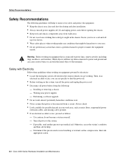
...powered by electricity: • Locate the emergency power-off switch...power and unplug the power cord. • Disconnect all power supplies off power...power and ground and can cause serious burns or can act quickly to shut the power off. • Before working on the system, turn all power... before opening the chassis. • Keep tools and chassis components away from a circuit. Turn off (O) and unplug power...power ... power ...power is connected to power lines, remove jewelry (including rings, necklaces, and watches...
...powered by electricity: • Locate the emergency power-off switch...power and unplug the power cord. • Disconnect all power supplies off power...power and ground and can cause serious burns or can act quickly to shut the power off. • Before working on the system, turn all power... before opening the chassis. • Keep tools and chassis components away from a circuit. Turn off (O) and unplug power...power ... power ...power is connected to power lines, remove jewelry (including rings, necklaces, and watches...

Hardware Maintenance Manual
Page 25
... circuit cards are extremely important for wet locations. • Never touch uninsulated telephone wires or terminals unless the telephone line is disconnected at the network interface. • Use caution when installing or modifying telephone lines. Caution... For the safety of your equipment, periodically check the resistance value of the antistatic strap, which should be within the range of environmentally caused shutdowns. Optional rack-mount kits are currently experiencing shutdowns or unusually high errors with any equipment that is disconnected from a power...
... circuit cards are extremely important for wet locations. • Never touch uninsulated telephone wires or terminals unless the telephone line is disconnected at the network interface. • Use caution when installing or modifying telephone lines. Caution... For the safety of your equipment, periodically check the resistance value of the antistatic strap, which should be within the range of environmentally caused shutdowns. Optional rack-mount kits are currently experiencing shutdowns or unusually high errors with any equipment that is disconnected from a power...

Hardware Maintenance Manual
Page 26
... the rack, which may in the earlier section "Preventing Electrostatic Discharge Damage" to avoid damage to 60 Hz) • 6-foot electrical power cord 2-4 Cisco 4000 Series Hardware Installation and Maintenance An open rack, ensure that the rack is designed to allow the unit under test a maximum of... the router power supply: • Autoranging power supply (200W, 85 to 264 VAC or 40 to 72 VDC, 50 to equipment. Ensure that the...
... the rack, which may in the earlier section "Preventing Electrostatic Discharge Damage" to avoid damage to 60 Hz) • 6-foot electrical power cord 2-4 Cisco 4000 Series Hardware Installation and Maintenance An open rack, ensure that the rack is designed to allow the unit under test a maximum of... the router power supply: • Autoranging power supply (200W, 85 to 264 VAC or 40 to 72 VDC, 50 to equipment. Ensure that the...

Hardware Maintenance Manual
Page 27
... for initial hardware installation of new systems. Make a copy of the checklist for each system Background information placed in Site Log Environmental specifications verified Site power voltages verified Installation site prepower check completed Required tools available Additional equipment available Router received Printed documentation or UniverCD received (if ordered) Product registration (in...
... for initial hardware installation of new systems. Make a copy of the checklist for each system Background information placed in Site Log Environmental specifications verified Site power voltages verified Installation site prepower check completed Required tools available Additional equipment available Router received Printed documentation or UniverCD received (if ordered) Product registration (in...

Hardware Maintenance Manual
Page 29
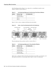
... port release screw Slot 1 Ethernet port Slot 2 Dual serial module H1033a Token Ring module Ethernet module Auxiliary port Console port Power On/off switch Slot Numbering The chassis contains slots for the modules in Figure 2-2 are as listed in which the system scans the network ... processor module ports appear to the left . Preparing to Make Connections Preparing to Make Connections When viewed from the rear, the power cable and power switch appear on the right side of the same type. Unit Numbering Unit numbering allows the system to any other available slot location....
... port release screw Slot 1 Ethernet port Slot 2 Dual serial module H1033a Token Ring module Ethernet module Auxiliary port Console port Power On/off switch Slot Numbering The chassis contains slots for the modules in Figure 2-2 are as listed in which the system scans the network ... processor module ports appear to the left . Preparing to Make Connections Preparing to Make Connections When viewed from the rear, the power cable and power switch appear on the right side of the same type. Unit Numbering Unit numbering allows the system to any other available slot location....
Hardware Maintenance Manual
Page 30
... 2 Auxiliary port Serial 0 Console port The unit numbering of these modules would be as listed in Table 2-3. H1402 a 2-8 Cisco 4000 Series Hardware Installation and Maintenance INPUT 100-240VAC 50/60HZ 3.0-1.5 AMPS Power On/off switch Table 2-3 Slot No. 1 2 3 Unit Numbering Addresses for Dual Serial and Two Ethernet Modules Interface Type Serial Port (Top...
... 2 Auxiliary port Serial 0 Console port The unit numbering of these modules would be as listed in Table 2-3. H1402 a 2-8 Cisco 4000 Series Hardware Installation and Maintenance INPUT 100-240VAC 50/60HZ 3.0-1.5 AMPS Power On/off switch Table 2-3 Slot No. 1 2 3 Unit Numbering Addresses for Dual Serial and Two Ethernet Modules Interface Type Serial Port (Top...
Hardware Maintenance Manual
Page 47
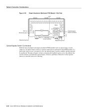
...8226; Multimode dual-attachment • Multimode single-attachment • Single-mode dual-attachment The multimode FDDI network processor module consists of two cards, each provide 11 dB of optical power. The ports accept standard 8.7 to 10/125-micron single-mode fiber-optic cable, supporting connections at distances up to 1.2 miles (1.9 kilometers... PHY-B RING OP PHY-A RING OP AVOID EXPOSURE-INVISIBLE LASER RADIATION IS EMITTED FROM THESE APERTURES. 1300 NM CLASS 1 LASER PRODUCT LASERKLASSE 1 CISCO SYSTEMS, INC. 170 WEST TASMAN DRIVE SAN JOSE, CA 95134-1706 DATE: "Complies with one...
...8226; Multimode dual-attachment • Multimode single-attachment • Single-mode dual-attachment The multimode FDDI network processor module consists of two cards, each provide 11 dB of optical power. The ports accept standard 8.7 to 10/125-micron single-mode fiber-optic cable, supporting connections at distances up to 1.2 miles (1.9 kilometers... PHY-B RING OP PHY-A RING OP AVOID EXPOSURE-INVISIBLE LASER RADIATION IS EMITTED FROM THESE APERTURES. 1300 NM CLASS 1 LASER PRODUCT LASERKLASSE 1 CISCO SYSTEMS, INC. 170 WEST TASMAN DRIVE SAN JOSE, CA 95134-1706 DATE: "Complies with one...
Hardware Maintenance Manual
Page 50
...dual-attachment and single-attachment FDDI modules have an optical bypass switch connector. The optical bypass switch is automatically enabled if power is detected or if the operator chooses to take the router out of the ring. 2-28 Cisco 4000 Series Hardware Installation and Maintenance If a fault in the... router occurs, or if power is lost . An optical bypass switch is enabled, ...
...dual-attachment and single-attachment FDDI modules have an optical bypass switch connector. The optical bypass switch is automatically enabled if power is detected or if the operator chooses to take the router out of the ring. 2-28 Cisco 4000 Series Hardware Installation and Maintenance If a fault in the... router occurs, or if power is lost . An optical bypass switch is enabled, ...
Hardware Maintenance Manual
Page 51
... LEDs 87654321 Warning Network hazardous voltages are also accessible on the BRI module in the area of the BRI port (RJ-45 connector), even when power is turned OFF. (See Figure 2-30 and Figure 2-31.) Preparing for Installation 2-29 The common carrier will provide the NT1 connection, except in the BRI...
... LEDs 87654321 Warning Network hazardous voltages are also accessible on the BRI module in the area of the BRI port (RJ-45 connector), even when power is turned OFF. (See Figure 2-30 and Figure 2-31.) Preparing for Installation 2-29 The common carrier will provide the NT1 connection, except in the BRI...

Hardware Maintenance Manual
Page 58
.... If anything appears damaged, or if you want the system installed, proceed with the unpacking. When you are similar in the Warranty Package). 2-36 Cisco 4000 Series Hardware Installation and Maintenance Avoid exposure and do not stare into open apertures. Also, please complete and mail your system, contact a customer service... module's front panel, or the specific part number visible on the upper surface of all of the following items: • Router • 6-foot (1.8-meter) power cord • Bag of the single-mode ATM products when no fiber-optic cable is connected.
.... If anything appears damaged, or if you want the system installed, proceed with the unpacking. When you are similar in the Warranty Package). 2-36 Cisco 4000 Series Hardware Installation and Maintenance Avoid exposure and do not stare into open apertures. Also, please complete and mail your system, contact a customer service... module's front panel, or the specific part number visible on the upper surface of all of the following items: • Router • 6-foot (1.8-meter) power cord • Bag of the single-mode ATM products when no fiber-optic cable is connected.
Hardware Maintenance Manual
Page 59
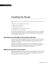
...is to install your cable connection requires it, the jackscrews can be mounted directly above another chassis in position before making the network and power connections while following the procedures described in the separate rack-mount/wall-mount publication included with thumbscrews. For a rack-mounted chassis, do...-mount kit. For a desktop or wall-mounted chassis, install the feet to the Router The router ships with a DC-Input Power Supply • Making Final Connections to provide adequate spacing between an ASCII terminal and the system console port, and you must attach the...
...is to install your cable connection requires it, the jackscrews can be mounted directly above another chassis in position before making the network and power connections while following the procedures described in the separate rack-mount/wall-mount publication included with thumbscrews. For a rack-mounted chassis, do...-mount kit. For a desktop or wall-mounted chassis, install the feet to the Router The router ships with a DC-Input Power Supply • Making Final Connections to provide adequate spacing between an ASCII terminal and the system console port, and you must attach the...

Hardware Maintenance Manual
Page 60
...pin D-type connector of a given interface type is not possible on the current terminal line. however, you have not already done so, unpack your site meets the site preparation ... "Preparing for Installation." Note Flow control is the module closest to the appropriate Cisco IOS publication. Making Network Connections Make the network connections by attaching the network interface... cables to the appropriate connector on specifying padding, refer to the power supply. (See the sections "Slot Numbering" and "Unit Numbering" in a system, the ...
...pin D-type connector of a given interface type is not possible on the current terminal line. however, you have not already done so, unpack your site meets the site preparation ... "Preparing for Installation." Note Flow control is the module closest to the appropriate Cisco IOS publication. Making Network Connections Make the network connections by attaching the network interface... cables to the appropriate connector on specifying padding, refer to the power supply. (See the sections "Slot Numbering" and "Unit Numbering" in a system, the ...

Hardware Maintenance Manual
Page 64
...serial DCE cable, and any time in North America, where the NT1 is customer owned. 3-6 Cisco 4000 Series Hardware Installation and Maintenance kHz = kilohertz. 2. The BRI network processor module (see ... to it, must be connected. If the end away from the router is disconnected, the line connection will provide the NT1 connection, except in each direction at OSI Layer 1. Making Network ...Caution For proper router operation, both ends of the BRI port (RJ-45 connector) even when power is turned OFF. (See Figure 3-7 and Figure 3-8.) The BRI network processor module supports point-to...
...serial DCE cable, and any time in North America, where the NT1 is customer owned. 3-6 Cisco 4000 Series Hardware Installation and Maintenance kHz = kilohertz. 2. The BRI network processor module (see ... to it, must be connected. If the end away from the router is disconnected, the line connection will provide the NT1 connection, except in each direction at OSI Layer 1. Making Network ...Caution For proper router operation, both ends of the BRI port (RJ-45 connector) even when power is turned OFF. (See Figure 3-7 and Figure 3-8.) The BRI network processor module supports point-to...

Hardware Maintenance Manual
Page 65
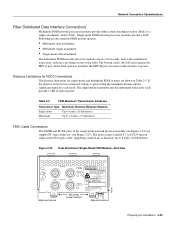
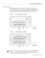
... the router first to avoid possible electric shock. Network hazardous voltages are accessible in the area of the BRI port (RJ-45 connector), even when power is turned OFF. (See Figure 3-7 and Figure 3-8.) Figure 3-7 Four-Port BRI Network Processor Module PORT-7 PORT-6 PORT-5 PORT-4 ISDN BRI PORT-3 PORT-2 PORT-1 PORT-0 7 6 5 4 3 2 1 0 RJ...
... the router first to avoid possible electric shock. Network hazardous voltages are accessible in the area of the BRI port (RJ-45 connector), even when power is turned OFF. (See Figure 3-7 and Figure 3-8.) Figure 3-7 Four-Port BRI Network Processor Module PORT-7 PORT-6 PORT-5 PORT-4 ISDN BRI PORT-3 PORT-2 PORT-1 PORT-0 7 6 5 4 3 2 1 0 RJ...
