
Hardware Maintenance Manual
Page 3
... original. All other remedy is error free or that aspects of the licensed materials, including the specific design and structure of individual programs, constitute trade secrets and/or copyrighted material of Cisco Systems, Inc. Cisco 4000 Series Hardware Installation and Maintenance Copyright © 1994-1995, Cisco Systems, Inc. Printed in subparagraph (c) of the Commercial Computer Software Restricted Rights clause at FAR...
... original. All other remedy is error free or that aspects of the licensed materials, including the specific design and structure of individual programs, constitute trade secrets and/or copyrighted material of Cisco Systems, Inc. Cisco 4000 Series Hardware Installation and Maintenance Copyright © 1994-1995, Cisco Systems, Inc. Printed in subparagraph (c) of the Commercial Computer Software Restricted Rights clause at FAR...

Hardware Maintenance Manual
Page 5
...Unit Numbering 2-7 Console Port and Auxiliary Port Connection Considerations 2-9 Console Port Connections 2-9 Auxiliary Port Connections 2-9 Network Connection Considerations 2-10 Ethernet Connections 2-10 Token Ring Connections 2-13 Serial Connections 2-15 Fiber Distributed Data Interface Connections 2-25 BRI Connections 2-29 Channelized T1 Connections 2-30 Channelized E1 Connections 2-32 ATM Connections 2-34 Inspecting the System 2-36 Chapter 3 Installing the Router 3-1 Rack-Mount and Wall-Mount Procedures Overview 3-1 Making Console Port Connections 3-1 Making Network Connections 3-2 Table...
...Unit Numbering 2-7 Console Port and Auxiliary Port Connection Considerations 2-9 Console Port Connections 2-9 Auxiliary Port Connections 2-9 Network Connection Considerations 2-10 Ethernet Connections 2-10 Token Ring Connections 2-13 Serial Connections 2-15 Fiber Distributed Data Interface Connections 2-25 BRI Connections 2-29 Channelized T1 Connections 2-30 Channelized E1 Connections 2-32 ATM Connections 2-34 Inspecting the System 2-36 Chapter 3 Installing the Router 3-1 Rack-Mount and Wall-Mount Procedures Overview 3-1 Making Console Port Connections 3-1 Making Network Connections 3-2 Table...

Hardware Maintenance Manual
Page 7
...-Port Serial Module Cable Assembly A-18 Ethernet Cable Pinouts A-19 Ethernet (AUI) Cable Pinouts A-19 RJ-45 10BaseT Connector Pinouts A-20 Token Ring Port Pinout A-21 BRI Pinout A-22 Channelized T1 Pinouts A-22 Channelized E1 Pinouts A-23 Appendix B Cisco 4000 Series Virtual Configuration Register B-1 Virtual Configuration Register Settings B-1 Changing Configuration Register Settings B-2 Configuring the Boot Field B-3 Enabling Booting from Flash Memory B-6 Appendix C Cisco 4000-M ROM Monitor C-1 Entering the Cisco 4000-M ROM Monitor Program C-1 Available ROM Monitor Commands C-2 Appendix...
...-Port Serial Module Cable Assembly A-18 Ethernet Cable Pinouts A-19 Ethernet (AUI) Cable Pinouts A-19 RJ-45 10BaseT Connector Pinouts A-20 Token Ring Port Pinout A-21 BRI Pinout A-22 Channelized T1 Pinouts A-22 Channelized E1 Pinouts A-23 Appendix B Cisco 4000 Series Virtual Configuration Register B-1 Virtual Configuration Register Settings B-1 Changing Configuration Register Settings B-2 Configuring the Boot Field B-3 Enabling Booting from Flash Memory B-6 Appendix C Cisco 4000-M ROM Monitor C-1 Entering the Cisco 4000-M ROM Monitor Program C-1 Available ROM Monitor Commands C-2 Appendix...

Hardware Maintenance Manual
Page 9
... 2-32 Cisco 4000 Series Chassis-Front Panel 1-2 Cisco 4000 Series Memory Systems and Software Images 1-4 Installation Checklist 2-5 Router-Rear View Showing Slot Numbering and Interface Ports 2-7 Router-Rear View Showing Serial Port Unit Numbering 2-8 Slot Filler Panel 2-9 Ethernet Network Processor Module with AUI and 10BaseT Connectors 2-11 Single-Port Ethernet Network Processor Module 10BaseT Port Connection 2-11 Single-Port Ethernet Network Processor Module AUI Port Connection 2-12 Extending the Transition Cable from the Ethernet Port 2-12 Dual-Port Ethernet Network Processor Module with...
... 2-32 Cisco 4000 Series Chassis-Front Panel 1-2 Cisco 4000 Series Memory Systems and Software Images 1-4 Installation Checklist 2-5 Router-Rear View Showing Slot Numbering and Interface Ports 2-7 Router-Rear View Showing Serial Port Unit Numbering 2-8 Slot Filler Panel 2-9 Ethernet Network Processor Module with AUI and 10BaseT Connectors 2-11 Single-Port Ethernet Network Processor Module 10BaseT Port Connection 2-11 Single-Port Ethernet Network Processor Module AUI Port Connection 2-12 Extending the Transition Cable from the Ethernet Port 2-12 Dual-Port Ethernet Network Processor Module with...

Hardware Maintenance Manual
Page 10
... AC-Input Power Supply-Rear View 3-20 DC-Input Power Supply Connections 3-21 Cisco 4000 Series-Front Panel Indicators 4-3 Dual-Port Ethernet Network Processor Module LEDs 4-4 Single-Port Ethernet Network Processor Module LEDs 4-4 Token Ring Module Network Connector 4-5 Four-Port Serial Network Processor Module Ports 4-6 G.703/G.704 Serial Network Processor Module Ports (DB-15) 4-6 Serial Port Labeled V2 4-7 Dual Serial Network Processor Module-Top View 4-8 Dual Serial Port LED Card-Side View 4-8 Dual-Attachment Single-Mode FDDI Module-End View 4-9 x Cisco 4000 Series Hardware Installation and...
... AC-Input Power Supply-Rear View 3-20 DC-Input Power Supply Connections 3-21 Cisco 4000 Series-Front Panel Indicators 4-3 Dual-Port Ethernet Network Processor Module LEDs 4-4 Single-Port Ethernet Network Processor Module LEDs 4-4 Token Ring Module Network Connector 4-5 Four-Port Serial Network Processor Module Ports 4-6 G.703/G.704 Serial Network Processor Module Ports (DB-15) 4-6 Serial Port Labeled V2 4-7 Dual Serial Network Processor Module-Top View 4-8 Dual Serial Port LED Card-Side View 4-8 Dual-Attachment Single-Mode FDDI Module-End View 4-9 x Cisco 4000 Series Hardware Installation and...

Hardware Maintenance Manual
Page 15
..., network connection considerations, and instructions for inspecting the new system. • Chapter 3, "Installing the Router," includes instructions for the router installer, who should be more up to date than printed documentation. Document Objectives This publication contains the initial site preparation, installation, troubleshooting, and selected upgrade and maintenance procedures. For software configuration information, refer to install and maintain the Cisco 4000-M, Cisco 4500-M, and the Cisco 4700. Use this publication follow: • Chapter 1, "Cisco 4000 Series...
..., network connection considerations, and instructions for inspecting the new system. • Chapter 3, "Installing the Router," includes instructions for the router installer, who should be more up to date than printed documentation. Document Objectives This publication contains the initial site preparation, installation, troubleshooting, and selected upgrade and maintenance procedures. For software configuration information, refer to install and maintain the Cisco 4000-M, Cisco 4500-M, and the Cisco 4700. Use this publication follow: • Chapter 1, "Cisco 4000 Series...

Hardware Maintenance Manual
Page 16
...-panel and network-processor module LED indicators. • Chapter 5, "Maintaining and Upgrading the Router," includes instructions for opening the chassis, replacing or adding network processor modules, and replacing single in-line memory modules (SIMMs). • Appendix A, "Cabling Specifications," provides cable illustrations, cable pinouts, and signal descriptions for the console and auxiliary ports, synchronous serial cables, and Ethernet (AUI) cables. • Appendix B, "Cisco 4000 Series Virtual Configuration Register," describes the Cisco 4000-M virtual configuration register and...
...-panel and network-processor module LED indicators. • Chapter 5, "Maintaining and Upgrading the Router," includes instructions for opening the chassis, replacing or adding network processor modules, and replacing single in-line memory modules (SIMMs). • Appendix A, "Cabling Specifications," provides cable illustrations, cable pinouts, and signal descriptions for the console and auxiliary ports, synchronous serial cables, and Ethernet (AUI) cables. • Appendix B, "Cisco 4000 Series Virtual Configuration Register," describes the Cisco 4000-M virtual configuration register and...

Hardware Maintenance Manual
Page 19
...hardware connections. External Differences in the router are all labeled Cisco 4000 Series on the chassis rear. For initial software configuration and operating information, refer to easily reconfigure the router when needs change. Cisco 4000 Series Overview 1-1 and the Cisco 4000-M contains a 40-MHz Motorola 68EC030 microprocessor. CHAPTER 1 Cisco 4000 Series Overview The Cisco 4000 series comprises the Cisco 4000-M, the Cisco 4500-M, and the Cisco 4700. All models provide a configurable modular router platform using network processor modules-individual modules that when installed...
...hardware connections. External Differences in the router are all labeled Cisco 4000 Series on the chassis rear. For initial software configuration and operating information, refer to easily reconfigure the router when needs change. Cisco 4000 Series Overview 1-1 and the Cisco 4000-M contains a 40-MHz Motorola 68EC030 microprocessor. CHAPTER 1 Cisco 4000 Series Overview The Cisco 4000 series comprises the Cisco 4000-M, the Cisco 4500-M, and the Cisco 4700. All models provide a configurable modular router platform using network processor modules-individual modules that when installed...

Hardware Maintenance Manual
Page 28
... - Removal or replacement of ongoing router maintenance and expansion history. Each time a procedure is completed. • Upgrades and removal or replacement procedures-Use the Site Log as additional equipment, and most provide either a V.35, EIA/TIA-449, or EIA-530 electrical interface. • Ethernet transceiver. • Token Ring media attachment unit (MAU). • Optical bypass switch or concentrator for multimode Fiber Distributed Data Interface (FDDI) connections. 2-6 Cisco 4000 Series Hardware Installation...
... - Removal or replacement of ongoing router maintenance and expansion history. Each time a procedure is completed. • Upgrades and removal or replacement procedures-Use the Site Log as additional equipment, and most provide either a V.35, EIA/TIA-449, or EIA-530 electrical interface. • Ethernet transceiver. • Token Ring media attachment unit (MAU). • Optical bypass switch or concentrator for multimode Fiber Distributed Data Interface (FDDI) connections. 2-6 Cisco 4000 Series Hardware Installation...

Hardware Maintenance Manual
Page 37
... distance limitations and potential electromagnetic interference (EMI) as a DB-25. (See Figure 2-13.) The router Console and Auxiliary ports also use EIA/TIA-232 connections; The recommended distance limits for Installation 2-15 All serial signals are also valid for them, you can support 4-Mbps rates. The network end of the adapter cable is completely lost. however, the serial module ports support synchronous connections, and the console and auxiliary ports support asynchronous connections.
... distance limitations and potential electromagnetic interference (EMI) as a DB-25. (See Figure 2-13.) The router Console and Auxiliary ports also use EIA/TIA-232 connections; The recommended distance limits for Installation 2-15 All serial signals are also valid for them, you can support 4-Mbps rates. The network end of the adapter cable is completely lost. however, the serial module ports support synchronous connections, and the console and auxiliary ports support asynchronous connections.

Hardware Maintenance Manual
Page 45
... command is for Installation 2-23 NRZI uses differential encoding to the related software documentation. NRZ format, which transmits streams of check digits per frame that follows, serial port 0 is an error-checking technique that the sender used for NRZI encoding: router# configure terminal interface serial 0 nrzi-encoding ^Z To disable NRZI encoding on the Four-Port Serial Module All Cisco 4000 series router serial interfaces support CRC-CCITT, a 16-bit cyclic redundancy check (CRC). CRC is configured for EIA/TIA-232 connections...
... command is for Installation 2-23 NRZI uses differential encoding to the related software documentation. NRZ format, which transmits streams of check digits per frame that follows, serial port 0 is an error-checking technique that the sender used for NRZI encoding: router# configure terminal interface serial 0 nrzi-encoding ^Z To disable NRZI encoding on the Four-Port Serial Module All Cisco 4000 series router serial interfaces support CRC-CCITT, a 16-bit cyclic redundancy check (CRC). CRC is configured for EIA/TIA-232 connections...

Hardware Maintenance Manual
Page 46
..., 0 underruns 0 output errors, 0 collisions, 1 interface resets, 0 restarts 880 carrier transitions The field underrun, in the output of the show interface command, may be shown, as in the example that universal serial means the four port serial module.) The following example: buffer size 2108 Universal Serial: DTE V.24 (RS-232) cable If the cable is attached to the appropriate software publications. 2-24 Cisco 4000 Series Hardware Installation and Maintenance If a cable is DCE...
..., 0 underruns 0 output errors, 0 collisions, 1 interface resets, 0 restarts 880 carrier transitions The field underrun, in the output of the show interface command, may be shown, as in the example that universal serial means the four port serial module.) The following example: buffer size 2108 Universal Serial: DTE V.24 (RS-232) cable If the cable is attached to the appropriate software publications. 2-24 Cisco 4000 Series Hardware Installation and Maintenance If a cable is DCE...
Hardware Maintenance Manual
Page 52
... specifications for the BRI cable are given in Figure 2-32, provides a controller for a remote site. 2-30 Cisco 4000 Series Hardware Installation and Maintenance Note The multiport BRI network processor module requires that supports ISDN PRI. nF = nanoFarad. On the CT1, the controller provides up to a channel service unit (CSU). This interface is presented to ISDN interfaces which have an unsynchronized master clock, the module's interfaces will occasionally lose some packets...
... specifications for the BRI cable are given in Figure 2-32, provides a controller for a remote site. 2-30 Cisco 4000 Series Hardware Installation and Maintenance Note The multiport BRI network processor module requires that supports ISDN PRI. nF = nanoFarad. On the CT1, the controller provides up to a channel service unit (CSU). This interface is presented to ISDN interfaces which have an unsynchronized master clock, the module's interfaces will occasionally lose some packets...

Hardware Maintenance Manual
Page 54
... J2 (see G.703 / Section 6.3 (CCITT specification) • Jitter attenuation starting at the E1 rate of jumpers J1, J3, J4, J5, and J7. The figure shows the cable impedance set the cable impedance to 120-ohm. 2-32 Cisco 4000 Series Hardware Installation and Maintenance LOOPBACK LOCAL ALARM REMOTE ALARM H3154 Network Connection Considerations Channelized E1 Connections The Cisco 4000 series router supports a channelized E1 (CE1) network processor module with capacitive coupling between the receive...
... J2 (see G.703 / Section 6.3 (CCITT specification) • Jitter attenuation starting at the E1 rate of jumpers J1, J3, J4, J5, and J7. The figure shows the cable impedance set the cable impedance to 120-ohm. 2-32 Cisco 4000 Series Hardware Installation and Maintenance LOOPBACK LOCAL ALARM REMOTE ALARM H3154 Network Connection Considerations Channelized E1 Connections The Cisco 4000 series router supports a channelized E1 (CE1) network processor module with capacitive coupling between the receive...

Hardware Maintenance Manual
Page 64
... to avoid possible electric shock. Use an appropriate cable to connect the BRI module directly to -multipoint wiring configuration. The BRI module does not support a point-to an Integrated Services Digital Network (ISDN) through the NT1. Making Network Connections Caution For proper router operation, both ends of the BRI port (RJ-45 connector) even when power is customer owned. 3-6 Cisco 4000 Series Hardware Installation and Maintenance If this chapter...
... to avoid possible electric shock. Use an appropriate cable to connect the BRI module directly to -multipoint wiring configuration. The BRI module does not support a point-to an Integrated Services Digital Network (ISDN) through the NT1. Making Network Connections Caution For proper router operation, both ends of the BRI port (RJ-45 connector) even when power is customer owned. 3-6 Cisco 4000 Series Hardware Installation and Maintenance If this chapter...
Hardware Maintenance Manual
Page 73
Step 10 After including all of the configuration options available and additional instructions for configuring the CT1 module. Installing the Router 3-15 Step 11 Write the new configuration to enable routing protocols and adjust the interface characteristics. Router(config-controller)# channel-group 0 timeslots 1,3-5,7 Router(config-controller)# %LINEPROTO-5-UPDOWN: Line protocol on Interface Serial1:0, changed state to down the Control key while you press Z) to modify. Router(config-controller)# int serial 1:0 Step 8 At the prompt, assign an IP address and...
Step 10 After including all of the configuration options available and additional instructions for configuring the CT1 module. Installing the Router 3-15 Step 11 Write the new configuration to enable routing protocols and adjust the interface characteristics. Router(config-controller)# channel-group 0 timeslots 1,3-5,7 Router(config-controller)# %LINEPROTO-5-UPDOWN: Line protocol on Interface Serial1:0, changed state to down the Control key while you press Z) to modify. Router(config-controller)# int serial 1:0 Step 8 At the prompt, assign an IP address and...
Hardware Maintenance Manual
Page 76
... to the user level: Router# disable The following example shows a basic configuration using using SVCs. The PVC command has the format atm pvc vc-id vpi vci encap [peak-rate sustained-rate burst-size]: Router(config-if)# atm pvc 1 1 32 aal5snap Router(config-if)# atm pvc 2 1 33 aal5snap Note VCI values 0-31 are used to assign protocol addresses to PVCs. Router(config-if)# atm pvc 1 0 5 qsaal 3-18 Cisco 4000 Series Hardware Installation and Maintenance...
... to the user level: Router# disable The following example shows a basic configuration using using SVCs. The PVC command has the format atm pvc vc-id vpi vci encap [peak-rate sustained-rate burst-size]: Router(config-if)# atm pvc 1 1 32 aal5snap Router(config-if)# atm pvc 2 1 33 aal5snap Note VCI values 0-31 are used to assign protocol addresses to PVCs. Router(config-if)# atm pvc 1 0 5 qsaal 3-18 Cisco 4000 Series Hardware Installation and Maintenance...
Hardware Maintenance Manual
Page 82
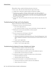
... shutdown. - Troubleshooting the Network Processor Modules and Cables Check for the following items to the section "Reading Front-Panel LED Indicators" later in the chapter "Preparing for connection. • System will not initialize. - Check the LEDs on , does the blower operate? - Suspect the processor or software. 4-2 Cisco 4000 Series Hardware Installation and Maintenance For complete information on LED indicators, refer to help isolate the problem: • Network processor module is...
... shutdown. - Troubleshooting the Network Processor Modules and Cables Check for the following items to the section "Reading Front-Panel LED Indicators" later in the chapter "Preparing for connection. • System will not initialize. - Check the LEDs on , does the blower operate? - Suspect the processor or software. 4-2 Cisco 4000 Series Hardware Installation and Maintenance For complete information on LED indicators, refer to help isolate the problem: • Network processor module is...
Hardware Maintenance Manual
Page 119
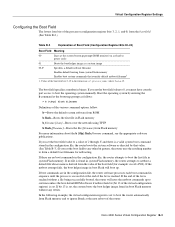
... 02-F Specifies a default netboot filename Enables default booting from system Flash memory Enables boot system commands that value. (See Table B-3.) If you must have console port access to form a default boot filename for example: cisco2-4500). If no boot commands in the configuration file, the router attempts to 0, you set , the system boots the boot helper image found in system Flash memory, the router attempts to ignore Break at the next reboot of the list is reached.
... 02-F Specifies a default netboot filename Enables default booting from system Flash memory Enables boot system commands that value. (See Table B-3.) If you must have console port access to form a default boot filename for example: cisco2-4500). If no boot commands in the configuration file, the router attempts to 0, you set , the system boots the boot helper image found in system Flash memory, the router attempts to ignore Break at the next reboot of the list is reached.

Hardware Maintenance Manual
Page 141
... dual-port A-7 four-port A-8 EIA-530 dual-port A-16 four-port A-18 EIA-TIA-232, four-port A-5 Ethernet (AUI) A-19 RJ-45 A-20 serial cable A-3-A-18 Token Ring A-21 V.35 dual-port A-10 four-port A-11 X.21 dual-port A-14 four-port A-15 polarity, Ethernet LED 4-5 port locations 2-7 software configuration, serial 4-8 power LED indication 3-22 light 4-3 specifications 1-3 supply features 2-4 system, troubleshooting 4-2 preparing for installation 2-1 to make connections 2-7 preventing ESD damage 2-3 preventive site configuration 2-4 printing summary of ROM monitor commands problem indications...
... dual-port A-7 four-port A-8 EIA-530 dual-port A-16 four-port A-18 EIA-TIA-232, four-port A-5 Ethernet (AUI) A-19 RJ-45 A-20 serial cable A-3-A-18 Token Ring A-21 V.35 dual-port A-10 four-port A-11 X.21 dual-port A-14 four-port A-15 polarity, Ethernet LED 4-5 port locations 2-7 software configuration, serial 4-8 power LED indication 3-22 light 4-3 specifications 1-3 supply features 2-4 system, troubleshooting 4-2 preparing for installation 2-1 to make connections 2-7 preventing ESD damage 2-3 preventive site configuration 2-4 printing summary of ROM monitor commands problem indications...


