
Hardware Maintenance Manual
Page 5
... of the Cisco 4000 Series 1-1 Series Specifications 1-2 Memory Systems 1-4 Chapter 2 Preparing for Installation 2-1 Safety Recommendations 2-2 Safety with Electricity 2-2 Preventing Electrostatic Discharge Damage 2-3 General Site Requirements 2-3 Site Environment 2-3 Site Configuration Precautions 2-4 Installation Checklist 2-5 Site Log 2-6 Required Tools and Equipment 2-6 Preparing to Make Connections 2-7 Slot Numbering 2-7 Unit Numbering 2-7 Console Port and Auxiliary Port Connection Considerations...
... of the Cisco 4000 Series 1-1 Series Specifications 1-2 Memory Systems 1-4 Chapter 2 Preparing for Installation 2-1 Safety Recommendations 2-2 Safety with Electricity 2-2 Preventing Electrostatic Discharge Damage 2-3 General Site Requirements 2-3 Site Environment 2-3 Site Configuration Precautions 2-4 Installation Checklist 2-5 Site Log 2-6 Required Tools and Equipment 2-6 Preparing to Make Connections 2-7 Slot Numbering 2-7 Unit Numbering 2-7 Console Port and Auxiliary Port Connection Considerations...

Hardware Maintenance Manual
Page 6
... 4-3 Reading Network Processor Module LED Indicators 4-4 Ethernet Network Processor Module LED Indicators 4-4 Token Ring Network Processor Module LED Indicators 4-5 Four Port Serial Module Indicators 4-6 Dual Serial Network Processor Module LED Indicators 4-7 FDDI Network Processor Module LED Indicators 4-9 BRI Network Processor Module LED Indicators... 5-9 Installing Main Memory SIMMs 5-11 Replacing Shared-Memory SIMMs 5-13 Inserting Shared-Memory SIMMs 5-14 Removing the Cisco 4500-M and Cisco 4700 Boot Helper Flash Memory SIMM 5-16 Installing Flash-Memory SIMMs 5-17 Replacing Boot ROMs in the...
... 4-3 Reading Network Processor Module LED Indicators 4-4 Ethernet Network Processor Module LED Indicators 4-4 Token Ring Network Processor Module LED Indicators 4-5 Four Port Serial Module Indicators 4-6 Dual Serial Network Processor Module LED Indicators 4-7 FDDI Network Processor Module LED Indicators 4-9 BRI Network Processor Module LED Indicators... 5-9 Installing Main Memory SIMMs 5-11 Replacing Shared-Memory SIMMs 5-13 Inserting Shared-Memory SIMMs 5-14 Removing the Cisco 4500-M and Cisco 4700 Boot Helper Flash Memory SIMM 5-16 Installing Flash-Memory SIMMs 5-17 Replacing Boot ROMs in the...

Hardware Maintenance Manual
Page 7
...) Cable Pinouts A-19 RJ-45 10BaseT Connector Pinouts A-20 Token Ring Port Pinout A-21 BRI Pinout A-22 Channelized T1 Pinouts A-22 Channelized E1 Pinouts A-23 Appendix B Cisco 4000 Series Virtual Configuration Register B-1 Virtual Configuration Register Settings B-1 Changing Configuration...Configuring the Boot Field B-3 Enabling Booting from Flash Memory B-6 Appendix C Cisco 4000-M ROM Monitor C-1 Entering the Cisco 4000-M ROM Monitor Program C-1 Available ROM Monitor Commands C-2 Appendix D Cisco 4500-M and Cisco 4700 ROM Monitor D-1 Entering the ROM Monitor Program D-1 Available ROM ...
...) Cable Pinouts A-19 RJ-45 10BaseT Connector Pinouts A-20 Token Ring Port Pinout A-21 BRI Pinout A-22 Channelized T1 Pinouts A-22 Channelized E1 Pinouts A-23 Appendix B Cisco 4000 Series Virtual Configuration Register B-1 Virtual Configuration Register Settings B-1 Changing Configuration...Configuring the Boot Field B-3 Enabling Booting from Flash Memory B-6 Appendix C Cisco 4000-M ROM Monitor C-1 Entering the Cisco 4000-M ROM Monitor Program C-1 Available ROM Monitor Commands C-2 Appendix D Cisco 4500-M and Cisco 4700 ROM Monitor D-1 Entering the ROM Monitor Program D-1 Available ROM ...

Hardware Maintenance Manual
Page 9
...Figure 2-30 Figure 2-31 Figure 2-32 Cisco 4000 Series Chassis-Front Panel 1-2 Cisco 4000 Series Memory Systems and Software Images 1-4 Installation Checklist 2-5 Router-Rear View Showing Slot Numbering and Interface Ports 2-7 Router-Rear View Showing Serial Port Unit Numbering 2-8 Slot Filler Panel 2-9 Ethernet...Multimode FDDI Module-End View 2-27 Dual-Attachment FDDI Optical Bypass Switch and PHY Connections 2-27 Single-Attachment Multimode FDDI Module-End View 2-28 4-Port BRI Network Processor Module 2-29 8-Port BRI Network Processor Module 2-29 Channelized T1 Network Interface Processor 2-31...
...Figure 2-30 Figure 2-31 Figure 2-32 Cisco 4000 Series Chassis-Front Panel 1-2 Cisco 4000 Series Memory Systems and Software Images 1-4 Installation Checklist 2-5 Router-Rear View Showing Slot Numbering and Interface Ports 2-7 Router-Rear View Showing Serial Port Unit Numbering 2-8 Slot Filler Panel 2-9 Ethernet...Multimode FDDI Module-End View 2-27 Dual-Attachment FDDI Optical Bypass Switch and PHY Connections 2-27 Single-Attachment Multimode FDDI Module-End View 2-28 4-Port BRI Network Processor Module 2-29 8-Port BRI Network Processor Module 2-29 Channelized T1 Network Interface Processor 2-31...

Hardware Maintenance Manual
Page 10
... Processor Module LEDs 4-4 Token Ring Module Network Connector 4-5 Four-Port Serial Network Processor Module Ports 4-6 G.703/G.704 Serial Network Processor Module Ports (DB-15) 4-6 Serial Port Labeled V2 4-7 Dual Serial Network Processor Module-Top View 4-8 Dual Serial Port LED Card-Side View 4-8 Dual-Attachment Single-Mode FDDI Module-End View 4-9 x Cisco 4000 Series Hardware Installation and Maintenance
... Processor Module LEDs 4-4 Token Ring Module Network Connector 4-5 Four-Port Serial Network Processor Module Ports 4-6 G.703/G.704 Serial Network Processor Module Ports (DB-15) 4-6 Serial Port Labeled V2 4-7 Dual Serial Network Processor Module-Top View 4-8 Dual Serial Port LED Card-Side View 4-8 Dual-Attachment Single-Mode FDDI Module-End View 4-9 x Cisco 4000 Series Hardware Installation and Maintenance

Hardware Maintenance Manual
Page 11
...Attachment Multimode FDDI Module-End View 4-10 Single-Attachment Multimode FDDI Module-End View 4-10 Eight-Port BRI Network Processor Module 4-11 Four-Port BRI Network Processor Module 4-11 Channelized T1 Network Interface Processor 4-12 Channelized E1 Network Interface Processor...5-3 Component Tray Removal for Chassis Without a Safety Latch 5-4 Typical Cisco 4000 Series Component Tray-Cisco 4000-M Shown 5-5 Network Processor Module Locations 5-6 Cisco 4000-M SIMM Locations 5-7 Cisco 4500-M and Cisco 4700 SIMM Locations 5-8 Cisco 4000 Series Main Memory SIMM 5-8 Removing Main Memory SIMMs 5-10 ...
...Attachment Multimode FDDI Module-End View 4-10 Single-Attachment Multimode FDDI Module-End View 4-10 Eight-Port BRI Network Processor Module 4-11 Four-Port BRI Network Processor Module 4-11 Channelized T1 Network Interface Processor 4-12 Channelized E1 Network Interface Processor...5-3 Component Tray Removal for Chassis Without a Safety Latch 5-4 Typical Cisco 4000 Series Component Tray-Cisco 4000-M Shown 5-5 Network Processor Module Locations 5-6 Cisco 4000-M SIMM Locations 5-7 Cisco 4500-M and Cisco 4700 SIMM Locations 5-8 Cisco 4000 Series Main Memory SIMM 5-8 Removing Main Memory SIMMs 5-10 ...

Hardware Maintenance Manual
Page 13
... Network Processor Module LED Indicators 4-7 Dual Serial Network Processor Module LED Indicators 4-9 Cisco 4000-M Console and Auxiliary Port Signals A-2 Cisco 4500-M and Cisco 4700 Console and Auxiliary Port Signals A-2 Dual Serial Module EIA/TIA-232 DTE and DCE Serial Cable Pinouts A-4 Four-Port Serial EIA/TIA-232 DTE Cable Pinout (DB-60 to DB-25) A-5 Four...
... Network Processor Module LED Indicators 4-7 Dual Serial Network Processor Module LED Indicators 4-9 Cisco 4000-M Console and Auxiliary Port Signals A-2 Cisco 4500-M and Cisco 4700 Console and Auxiliary Port Signals A-2 Dual Serial Module EIA/TIA-232 DTE and DCE Serial Cable Pinouts A-4 Four-Port Serial EIA/TIA-232 DTE Cable Pinout (DB-60 to DB-25) A-5 Four...
Hardware Maintenance Manual
Page 14
Table A-21 Table A-22 Table A-23 Table A-24 Table B-1 Table B-2 Table B-3 Table B-4 Table B-5 Table C-1 BRI Port Pinout (RJ-45) A-22 T1 Null-Modem Cable Pinouts (P/N 72-0800-xx) A-23 T1 Straight-Through Cable Pinouts (P/N 72-0799-xx) A-23 E1 Interface Cable ... Field (Configuration Register Bits 00-03) B-3 Default Boot Filenames B-4 Configuration Register Settings for Broadcast Address Destination B-5 System Console Terminal Baud Rate Settings B-5 O Command Options C-3 xiv Cisco 4000 Series Hardware Installation and Maintenance
Table A-21 Table A-22 Table A-23 Table A-24 Table B-1 Table B-2 Table B-3 Table B-4 Table B-5 Table C-1 BRI Port Pinout (RJ-45) A-22 T1 Null-Modem Cable Pinouts (P/N 72-0800-xx) A-23 T1 Straight-Through Cable Pinouts (P/N 72-0799-xx) A-23 E1 Interface Cable ... Field (Configuration Register Bits 00-03) B-3 Default Boot Filenames B-4 Configuration Register Settings for Broadcast Address Destination B-5 System Console Terminal Baud Rate Settings B-5 O Command Options C-3 xiv Cisco 4000 Series Hardware Installation and Maintenance

Hardware Maintenance Manual
Page 15
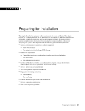
... configuration information, refer to date than printed documentation. Document Organization The major sections of this publication to Ordering Cisco Documentation, which is available both as a single CD and as an electronic or electromechanical technician. To order UniverCD... To order UniverCD, Cisco's online library of the Cisco 4000 series features and physical specifications. • Chapter 2, "Preparing for Installation," includes safety recommendations, tools and equipment, site requirements, an installation checklist, console and auxiliary port cable connection considerations, ...
... configuration information, refer to date than printed documentation. Document Organization The major sections of this publication to Ordering Cisco Documentation, which is available both as a single CD and as an electronic or electromechanical technician. To order UniverCD... To order UniverCD, Cisco's online library of the Cisco 4000 series features and physical specifications. • Chapter 2, "Preparing for Installation," includes safety recommendations, tools and equipment, site requirements, an installation checklist, console and auxiliary port cable connection considerations, ...

Hardware Maintenance Manual
Page 16
... network processor modules, and replacing single in-line memory modules (SIMMs). • Appendix A, "Cabling Specifications," provides cable illustrations, cable pinouts, and signal descriptions for the console and auxiliary ports, synchronous serial cables, and Ethernet (AUI) cables. • Appendix B, "Cisco 4000 Series Virtual Configuration Register," describes the Cisco 4000-M virtual configuration register and procedures for...
... network processor modules, and replacing single in-line memory modules (SIMMs). • Appendix A, "Cabling Specifications," provides cable illustrations, cable pinouts, and signal descriptions for the console and auxiliary ports, synchronous serial cables, and Ethernet (AUI) cables. • Appendix B, "Cisco 4000 Series Virtual Configuration Register," describes the Cisco 4000-M virtual configuration register and procedures for...

Hardware Maintenance Manual
Page 20
... and dual Token Ring, dual Ethernet, and FDDI modules. 1-2 Cisco 4000 Series Hardware Installation and Maintenance The Cisco 4500-M and Cisco 4700 can be placed in any of a Cisco 4000 series router. Note The Cisco 4500-M and Cisco 4700 support all network processor modules except the single-port Ethernet network processor module and early versions of excessively...
... and dual Token Ring, dual Ethernet, and FDDI modules. 1-2 Cisco 4000 Series Hardware Installation and Maintenance The Cisco 4500-M and Cisco 4700 can be placed in any of a Cisco 4000 series router. Note The Cisco 4500-M and Cisco 4700 support all network processor modules except the single-port Ethernet network processor module and early versions of excessively...

Hardware Maintenance Manual
Page 21
...-compatible. 2. Series Specifications Table 1-1 lists the physical specifications for the Cisco 4000 series routers. AWG-American Wire Gauge 2. EIA-530 DTE Console Port EIA/TIA-232 DB-25 female connector Auxiliary Port EIA/TIA-232 DB-25 male connector Nonoperating Temperature -40 to 185&#...176;F (-40 to 85°C) Operating Humidity 5 to 95%, noncondensing Operating Temperature 32 to 104°F (0 to 16 MB 1. DRAM-Dynamic random access memory. 3. Cisco 4000 Series Overview...
...-compatible. 2. Series Specifications Table 1-1 lists the physical specifications for the Cisco 4000 series routers. AWG-American Wire Gauge 2. EIA-530 DTE Console Port EIA/TIA-232 DB-25 female connector Auxiliary Port EIA/TIA-232 DB-25 male connector Nonoperating Temperature -40 to 185&#...176;F (-40 to 85°C) Operating Humidity 5 to 95%, noncondensing Operating Temperature 32 to 104°F (0 to 16 MB 1. DRAM-Dynamic random access memory. 3. Cisco 4000 Series Overview...
Hardware Maintenance Manual
Page 23
... and equipment required for installation • Preparations for inspecting the system are included in the section "Inspecting the System." Unit numbering • Console and auxiliary port connection considerations • Network connection considerations • New system inspection guidelines Preparing for router installation. This chapter includes the following preinstallation requirements: • Safety recommendations...
... and equipment required for installation • Preparations for inspecting the system are included in the section "Inspecting the System." Unit numbering • Console and auxiliary port connection considerations • Network connection considerations • New system inspection guidelines Preparing for router installation. This chapter includes the following preinstallation requirements: • Safety recommendations...

Hardware Maintenance Manual
Page 26
...rack (and in the earlier section "Preventing Electrostatic Discharge Damage" to avoid damage to 60 Hz) • 6-foot electrical power cord 2-4 Cisco 4000 Series Hardware Installation and Maintenance Damage from one chassis can help to ensure that you are features of spikes and noise). Install a power... rack, which may in turn interrupt and redirect the flow of the equipment above. • Baffles can be drawn into the intake port of the next. • Always follow the ESD-prevention procedures in adjacent racks) to allow cooling air to acceptable operating temperatures without ...
...rack (and in the earlier section "Preventing Electrostatic Discharge Damage" to avoid damage to 60 Hz) • 6-foot electrical power cord 2-4 Cisco 4000 Series Hardware Installation and Maintenance Damage from one chassis can help to ensure that you are features of spikes and noise). Install a power... rack, which may in turn interrupt and redirect the flow of the equipment above. • Baffles can be drawn into the intake port of the next. • Always follow the ESD-prevention procedures in adjacent racks) to allow cooling air to acceptable operating temperatures without ...

Hardware Maintenance Manual
Page 27
... (if ordered) Product registration (in warranty package) completed and mailed Chassis components verified Software version verified Initial electrical connections established ASCII terminal attached to console port Signal distance limits verified Startup sequence steps completed Initial system operation verified Verified by Router name Router serial number Notes: Date Preparing for each system...
... (if ordered) Product registration (in warranty package) completed and mailed Chassis components verified Software version verified Initial electrical connections established ASCII terminal attached to console port Signal distance limits verified Startup sequence steps completed Initial system operation verified Verified by Router name Router serial number Notes: Date Preparing for each system...

Hardware Maintenance Manual
Page 28
...EIA-530 electrical interface. • Ethernet transceiver. • Token Ring media attachment unit (MAU). • Optical bypass switch or concentrator for each serial port to connect the port with the correct framing and ones density. (Some telephone systems require a minimum number of 1 bits per time unit ...router: • ESD cord and wrist strap • Screwdrivers, Number 1 and Number 2 Phillips • One serial port adapter cable for multimode Fiber Distributed Data Interface (FDDI) connections. 2-6 Cisco 4000 Series Hardware Installation and Maintenance Configuration changes -
...EIA-530 electrical interface. • Ethernet transceiver. • Token Ring media attachment unit (MAU). • Optical bypass switch or concentrator for each serial port to connect the port with the correct framing and ones density. (Some telephone systems require a minimum number of 1 bits per time unit ...router: • ESD cord and wrist strap • Screwdrivers, Number 1 and Number 2 Phillips • One serial port adapter cable for multimode Fiber Distributed Data Interface (FDDI) connections. 2-6 Cisco 4000 Series Hardware Installation and Maintenance Configuration changes -

Hardware Maintenance Manual
Page 29
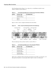
... Slot Numbering and Interface Ports Slot 3 Token Ring port 10BaseT Chassis Serial interface ports port release screw Slot 1 Ethernet port Slot 2 Dual serial module H1033a Token Ring module Ethernet module Auxiliary port Console port Power On/off switch Slot Numbering The chassis contains slots for Installation 2-7 The system console port, auxiliary (AUX) port, and network processor module ports appear to the...
... Slot Numbering and Interface Ports Slot 3 Token Ring port 10BaseT Chassis Serial interface ports port release screw Slot 1 Ethernet port Slot 2 Dual serial module H1033a Token Ring module Ethernet module Auxiliary port Console port Power On/off switch Slot Numbering The chassis contains slots for Installation 2-7 The system console port, auxiliary (AUX) port, and network processor module ports appear to the...
Hardware Maintenance Manual
Page 30
... airflow. INPUT 100-240VAC 50/60HZ 3.0-1.5 AMPS Power On/off switch Table 2-3 Slot No. 1 2 3 Unit Numbering Addresses for Dual Serial and Two Ethernet Modules Interface Type Serial Port (Top) Serial Port (Bottom) Ethernet Ethernet Unit Address No. 1 0 0 1 Figure... in Table 2-3. H1402 a 2-8 Cisco 4000 Series Hardware Installation and Maintenance Table 2-2 Slot No. 1 2 3 Unit Numbering Addresses for Three Dual Serial Modules Interface Type Serial Port (Top) Serial Port (Bottom) Serial Port (Top) Serial Port (Bottom) Serial Port (Top) Serial Port (Bottom) Unit Address No. 1...
... airflow. INPUT 100-240VAC 50/60HZ 3.0-1.5 AMPS Power On/off switch Table 2-3 Slot No. 1 2 3 Unit Numbering Addresses for Dual Serial and Two Ethernet Modules Interface Type Serial Port (Top) Serial Port (Bottom) Ethernet Ethernet Unit Address No. 1 0 0 1 Figure... in Table 2-3. H1402 a 2-8 Cisco 4000 Series Hardware Installation and Maintenance Table 2-2 Slot No. 1 2 3 Unit Numbering Addresses for Three Dual Serial Modules Interface Type Serial Port (Top) Serial Port (Bottom) Serial Port (Top) Serial Port (Bottom) Serial Port (Top) Serial Port (Bottom) Unit Address No. 1...

Hardware Maintenance Manual
Page 31
... Considerations Available Slot H1034a Alignment groove Mounting screw locations Alignment groove Console Port and Auxiliary Port Connection Considerations The following sections describe the console port and auxiliary port found on all Cisco 4000 series routers. Console Port Connections Each router includes an asynchronous router console port (female DB-25 connector) wired as a data communications equipment (DCE) device...
... Considerations Available Slot H1034a Alignment groove Mounting screw locations Alignment groove Console Port and Auxiliary Port Connection Considerations The following sections describe the console port and auxiliary port found on all Cisco 4000 series routers. Console Port Connections Each router includes an asynchronous router console port (female DB-25 connector) wired as a data communications equipment (DCE) device...

Hardware Maintenance Manual
Page 32
... Module Connections Each single-port Ethernet network processor module has an Ethernet AUI connector and a 10BaseT connector. (See Figure 2-5.) (Only one per line. Edit with CTRL/Z interface ethernet 0 media-type aui ^z router# write memory Refer to the router software publications for a Cisco 4000 series router. Network Connection Considerations Network Connection Considerations This section...
... Module Connections Each single-port Ethernet network processor module has an Ethernet AUI connector and a 10BaseT connector. (See Figure 2-5.) (Only one per line. Edit with CTRL/Z interface ethernet 0 media-type aui ^z router# write memory Refer to the router software publications for a Cisco 4000 series router. Network Connection Considerations Network Connection Considerations This section...


