Hardware Maintenance Manual
Page 1
Cisco 4000 Series Hardware Installation and Maintenance Corporate Headquarters 170 W. Tasman Drive San Jose, CA 95134-1706 USA 408 526-4000 800 553-NETS Customer Order Number: DOC-4000IM4 Text Part Number: 78-0952-04
Cisco 4000 Series Hardware Installation and Maintenance Corporate Headquarters 170 W. Tasman Drive San Jose, CA 95134-1706 USA 408 526-4000 800 553-NETS Customer Order Number: DOC-4000IM4 Text Part Number: 78-0952-04

Hardware Maintenance Manual
Page 3
...Catalyst, CD-PAC, CiscoFusion, Cisco IOS, CiscoView, CiscoWorks, EtherChannel, IGRP, LAN2LAN, LAN2LAN Enterprise, LAN2LAN Remote Office, LAN2PC, LightStream, Newport Systems Solutions, Packet, PC2LAN/X.25, Point and Click Internetworking, SMARTnet, SwitchProbe, SwitchVision, SynchroniCD, The Cell, UniverCD, WNIC, Workgroup Director, Workgroup Stack, and XCI are trademarks, Access by Cisco...MANUAL, EVEN IF CISCO HAS BEEN ADVISED OF THE POSSIBILITY OF SUCH DAMAGES. Notice of shipment. Cisco 4000 Series Hardware Installation and Maintenance Copyright © 1994-1995, Cisco Systems, Inc. ...
...Catalyst, CD-PAC, CiscoFusion, Cisco IOS, CiscoView, CiscoWorks, EtherChannel, IGRP, LAN2LAN, LAN2LAN Enterprise, LAN2LAN Remote Office, LAN2PC, LightStream, Newport Systems Solutions, Packet, PC2LAN/X.25, Point and Click Internetworking, SMARTnet, SwitchProbe, SwitchVision, SynchroniCD, The Cell, UniverCD, WNIC, Workgroup Director, Workgroup Stack, and XCI are trademarks, Access by Cisco...MANUAL, EVEN IF CISCO HAS BEEN ADVISED OF THE POSSIBILITY OF SUCH DAMAGES. Notice of shipment. Cisco 4000 Series Hardware Installation and Maintenance Copyright © 1994-1995, Cisco Systems, Inc. ...

Hardware Maintenance Manual
Page 5
TABLE OF CONTENTS About This Manual xv Document Objectives xv Audience xv Document Organization xv Document Conventions xvi Chapter 1 Cisco 4000 Series Overview 1-1 External Differences in Models of the Cisco 4000 Series 1-1 Series Specifications 1-2 Memory Systems 1-4 Chapter 2 Preparing for Installation 2-1 Safety Recommendations 2-2 Safety with Electricity 2-2 Preventing Electrostatic Discharge Damage 2-3 General Site Requirements 2-3 Site Environment 2-3 Site Configuration...
TABLE OF CONTENTS About This Manual xv Document Objectives xv Audience xv Document Organization xv Document Conventions xvi Chapter 1 Cisco 4000 Series Overview 1-1 External Differences in Models of the Cisco 4000 Series 1-1 Series Specifications 1-2 Memory Systems 1-4 Chapter 2 Preparing for Installation 2-1 Safety Recommendations 2-2 Safety with Electricity 2-2 Preventing Electrostatic Discharge Damage 2-3 General Site Requirements 2-3 Site Environment 2-3 Site Configuration...

Hardware Maintenance Manual
Page 6
... 5-6 Replacing Main Memory SIMMs 5-8 Removing Main Memory SIMMS 5-9 Installing Main Memory SIMMs 5-11 Replacing Shared-Memory SIMMs 5-13 Inserting Shared-Memory SIMMs 5-14 Removing the Cisco 4500-M and Cisco 4700 Boot Helper Flash Memory SIMM 5-16 Installing Flash-Memory SIMMs 5-17 Replacing Boot ROMs in the...
... 5-6 Replacing Main Memory SIMMs 5-8 Removing Main Memory SIMMS 5-9 Installing Main Memory SIMMs 5-11 Replacing Shared-Memory SIMMs 5-13 Inserting Shared-Memory SIMMs 5-14 Removing the Cisco 4500-M and Cisco 4700 Boot Helper Flash Memory SIMM 5-16 Installing Flash-Memory SIMMs 5-17 Replacing Boot ROMs in the...

Hardware Maintenance Manual
Page 7
... Pinouts A-19 RJ-45 10BaseT Connector Pinouts A-20 Token Ring Port Pinout A-21 BRI Pinout A-22 Channelized T1 Pinouts A-22 Channelized E1 Pinouts A-23 Appendix B Cisco 4000 Series Virtual Configuration Register B-1 Virtual Configuration Register Settings B-1 Changing Configuration Register Settings B-2 Configuring the Boot Field B-3 Enabling Booting from Flash Memory B-6 Appendix...
... Pinouts A-19 RJ-45 10BaseT Connector Pinouts A-20 Token Ring Port Pinout A-21 BRI Pinout A-22 Channelized T1 Pinouts A-22 Channelized E1 Pinouts A-23 Appendix B Cisco 4000 Series Virtual Configuration Register B-1 Virtual Configuration Register Settings B-1 Changing Configuration Register Settings B-2 Configuring the Boot Field B-3 Enabling Booting from Flash Memory B-6 Appendix...

Hardware Maintenance Manual
Page 8
For European Community Use Only F-1 viii Cisco 4000 Series Hardware Installation and Maintenance
For European Community Use Only F-1 viii Cisco 4000 Series Hardware Installation and Maintenance

Hardware Maintenance Manual
Page 9
...Figure 2-24 Figure 2-25 Figure 2-26 Figure 2-27 Figure 2-28 Figure 2-29 Figure 2-30 Figure 2-31 Figure 2-32 Cisco 4000 Series Chassis-Front Panel 1-2 Cisco 4000 Series Memory Systems and Software Images 1-4 Installation Checklist 2-5 Router-Rear View Showing Slot Numbering and Interface Ports 2-7 Router-Rear View... Multimode FDDI Network Interface Connector, MIC Type 2-26 Dual-Attachment Multimode FDDI Module-End View 2-27 Dual-Attachment FDDI Optical Bypass Switch and PHY Connections 2-27 Single-Attachment Multimode FDDI Module-End View 2-28 4-Port BRI Network Processor Module 2-29 8-Port BRI ...
...Figure 2-24 Figure 2-25 Figure 2-26 Figure 2-27 Figure 2-28 Figure 2-29 Figure 2-30 Figure 2-31 Figure 2-32 Cisco 4000 Series Chassis-Front Panel 1-2 Cisco 4000 Series Memory Systems and Software Images 1-4 Installation Checklist 2-5 Router-Rear View Showing Slot Numbering and Interface Ports 2-7 Router-Rear View... Multimode FDDI Network Interface Connector, MIC Type 2-26 Dual-Attachment Multimode FDDI Module-End View 2-27 Dual-Attachment FDDI Optical Bypass Switch and PHY Connections 2-27 Single-Attachment Multimode FDDI Module-End View 2-28 4-Port BRI Network Processor Module 2-29 8-Port BRI ...

Hardware Maintenance Manual
Page 10
... Making Single-Attachment Multimode FDDI Connections 3-12 Single-Mode Dual-Attachment FDDI Connections 3-13 Cisco 4000 Series DC-Input Power Supply-Rear View 3-20 Cisco 4000 Series AC-Input Power Supply-Rear View 3-20 DC-Input Power Supply Connections 3-21 Cisco 4000 Series-Front Panel Indicators 4-3 Dual-Port Ethernet Network Processor Module LEDs 4-4 Single-Port Ethernet... Port Labeled V2 4-7 Dual Serial Network Processor Module-Top View 4-8 Dual Serial Port LED Card-Side View 4-8 Dual-Attachment Single-Mode FDDI Module-End View 4-9 x Cisco 4000 Series Hardware Installation and Maintenance
... Making Single-Attachment Multimode FDDI Connections 3-12 Single-Mode Dual-Attachment FDDI Connections 3-13 Cisco 4000 Series DC-Input Power Supply-Rear View 3-20 Cisco 4000 Series AC-Input Power Supply-Rear View 3-20 DC-Input Power Supply Connections 3-21 Cisco 4000 Series-Front Panel Indicators 4-3 Dual-Port Ethernet Network Processor Module LEDs 4-4 Single-Port Ethernet... Port Labeled V2 4-7 Dual Serial Network Processor Module-Top View 4-8 Dual Serial Port LED Card-Side View 4-8 Dual-Attachment Single-Mode FDDI Module-End View 4-9 x Cisco 4000 Series Hardware Installation and Maintenance

Hardware Maintenance Manual
Page 11
... Tray Removal for Chassis With a Safety Latch 5-3 Component Tray Removal for Chassis Without a Safety Latch 5-4 Typical Cisco 4000 Series Component Tray-Cisco 4000-M Shown 5-5 Network Processor Module Locations 5-6 Cisco 4000-M SIMM Locations 5-7 Cisco 4500-M and Cisco 4700 SIMM Locations 5-8 Cisco 4000 Series Main Memory SIMM 5-8 Removing Main Memory SIMMs 5-10 Installing Main Memory SIMMs 5-12 Inserting Shared-Memory...
... Tray Removal for Chassis With a Safety Latch 5-3 Component Tray Removal for Chassis Without a Safety Latch 5-4 Typical Cisco 4000 Series Component Tray-Cisco 4000-M Shown 5-5 Network Processor Module Locations 5-6 Cisco 4000-M SIMM Locations 5-7 Cisco 4500-M and Cisco 4700 SIMM Locations 5-8 Cisco 4000 Series Main Memory SIMM 5-8 Removing Main Memory SIMMs 5-10 Installing Main Memory SIMMs 5-12 Inserting Shared-Memory...

Hardware Maintenance Manual
Page 12
Figure A-14 Figure A-15 Figure A-16 Figure A-17 E1 Interface Cable for 75-Ohm, Unbalanced Connections (with BNC Connectors) A-23 E1 Interface Cable for 120-Ohm, Balanced Connections (with DB-15 Connectors) A-24 E1 Interface Cable for 120-Ohm, Balanced Connections (with Twinax Connectors) A-24 E1 Interface Cable for 120-Ohm, Balanced Connections (with RJ-45 Connector) A-24 xii Cisco 4000 Series Hardware Installation and Maintenance
Figure A-14 Figure A-15 Figure A-16 Figure A-17 E1 Interface Cable for 75-Ohm, Unbalanced Connections (with BNC Connectors) A-23 E1 Interface Cable for 120-Ohm, Balanced Connections (with DB-15 Connectors) A-24 E1 Interface Cable for 120-Ohm, Balanced Connections (with Twinax Connectors) A-24 E1 Interface Cable for 120-Ohm, Balanced Connections (with RJ-45 Connector) A-24 xii Cisco 4000 Series Hardware Installation and Maintenance

Hardware Maintenance Manual
Page 13
...Table A-12 Table A-13 Table A-14 Table A-15 Table A-16 Table A-17 Table A-18 Table A-19 Table A-20 Cisco 4000 Series Physical Specifications 1-3 Cisco 4000 Series Processor and Memory Specifications 1-3 Unit Numbering for Dual Serial, Ethernet, and Token Ring Modules 2-7 Unit Numbering Addresses for Dual Serial... Four Port Serial Network Processor Module LED Indicators 4-7 Dual Serial Network Processor Module LED Indicators 4-9 Cisco 4000-M Console and Auxiliary Port Signals A-2 Cisco 4500-M and Cisco 4700 Console and Auxiliary Port Signals A-2 Dual Serial Module EIA/TIA-232 DTE and DCE Serial ...
...Table A-12 Table A-13 Table A-14 Table A-15 Table A-16 Table A-17 Table A-18 Table A-19 Table A-20 Cisco 4000 Series Physical Specifications 1-3 Cisco 4000 Series Processor and Memory Specifications 1-3 Unit Numbering for Dual Serial, Ethernet, and Token Ring Modules 2-7 Unit Numbering Addresses for Dual Serial... Four Port Serial Network Processor Module LED Indicators 4-7 Dual Serial Network Processor Module LED Indicators 4-9 Cisco 4000-M Console and Auxiliary Port Signals A-2 Cisco 4500-M and Cisco 4700 Console and Auxiliary Port Signals A-2 Dual Serial Module EIA/TIA-232 DTE and DCE Serial ...
Hardware Maintenance Manual
Page 14
... Field (Configuration Register Bits 00-03) B-3 Default Boot Filenames B-4 Configuration Register Settings for Broadcast Address Destination B-5 System Console Terminal Baud Rate Settings B-5 O Command Options C-3 xiv Cisco 4000 Series Hardware Installation and Maintenance
... Field (Configuration Register Bits 00-03) B-3 Default Boot Filenames B-4 Configuration Register Settings for Broadcast Address Destination B-5 System Console Terminal Baud Rate Settings B-5 O Command Options C-3 xiv Cisco 4000 Series Hardware Installation and Maintenance

Hardware Maintenance Manual
Page 15
About This Manual This section discusses the objectives, audience, organization, and conventions of the Cisco 4000 series features and physical specifications. • Chapter 2, "Preparing for Installation," includes safety recommendations, tools and equipment, site... to date than printed documentation. About This Manual xv Use this publication follow: • Chapter 1, "Cisco 4000 Series Overview," contains an overview of the Cisco 4000 Series Hardware Installation and Maintenance publication. UniverCD is for rack-mounting and wall-mounting the router, making external connections...
About This Manual This section discusses the objectives, audience, organization, and conventions of the Cisco 4000 series features and physical specifications. • Chapter 2, "Preparing for Installation," includes safety recommendations, tools and equipment, site... to date than printed documentation. About This Manual xv Use this publication follow: • Chapter 1, "Cisco 4000 Series Overview," contains an overview of the Cisco 4000 Series Hardware Installation and Maintenance publication. UniverCD is for rack-mounting and wall-mounting the router, making external connections...

Hardware Maintenance Manual
Page 16
... Conditions for the European Community," describes the operating conditions for which you enter is in screen font, with default responses in square brackets ([ ]). xvi Cisco 4000 Series Hardware Installation and Maintenance Note Means reader take note. Document Conventions This manual uses the following conventions to materials not contained in this manual. Notes...
... Conditions for the European Community," describes the operating conditions for which you enter is in screen font, with default responses in square brackets ([ ]). xvi Cisco 4000 Series Hardware Installation and Maintenance Note Means reader take note. Document Conventions This manual uses the following conventions to materials not contained in this manual. Notes...

Hardware Maintenance Manual
Page 18
Document Conventions xviii Cisco 4000 Series Hardware Installation and Maintenance
Document Conventions xviii Cisco 4000 Series Hardware Installation and Maintenance

Hardware Maintenance Manual
Page 19
...router when needs change. External Differences in Models of the Cisco 4700 reads Model 4700. CHAPTER 1 Cisco 4000 Series Overview The Cisco 4000 series comprises the Cisco 4000-M, the Cisco 4500-M, and the Cisco 4700. Note This publication contains the initial hardware installation and... modular router platform using network processor modules-individual modules that when installed in the Cisco 4000 series, the Cisco 4700 contains a 133-MHz Orion RISC microprocessor from IDT; the Cisco 4500-M contains a 100-MHz Orion RISC microprocessor from Integrated Device Technology, Incorporated ...
...router when needs change. External Differences in Models of the Cisco 4700 reads Model 4700. CHAPTER 1 Cisco 4000 Series Overview The Cisco 4000 series comprises the Cisco 4000-M, the Cisco 4500-M, and the Cisco 4700. Note This publication contains the initial hardware installation and... modular router platform using network processor modules-individual modules that when installed in the Cisco 4000 series, the Cisco 4700 contains a 133-MHz Orion RISC microprocessor from IDT; the Cisco 4500-M contains a 100-MHz Orion RISC microprocessor from Integrated Device Technology, Incorporated ...

Hardware Maintenance Manual
Page 20
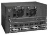
... support all network processor modules except the single-port Ethernet network processor module and early versions of a Cisco 4000 series router. The BRI 4-port and 8-port network interface modules (NP-4B/NP-8B) are not compatible with...and dual Token Ring, dual Ethernet, and FDDI modules. 1-2 Cisco 4000 Series Hardware Installation and Maintenance Figure 1-1 Cisco 4000 Series Chassis-Front Panel 1 DATA OK 2 DATA OK 3 DATA OK OK POWER SERIES H3590 Series Specifications Design specifications for the Cisco 4000 series follow: • Modular router platform • Flash memory ...
... support all network processor modules except the single-port Ethernet network processor module and early versions of a Cisco 4000 series router. The BRI 4-port and 8-port network interface modules (NP-4B/NP-8B) are not compatible with...and dual Token Ring, dual Ethernet, and FDDI modules. 1-2 Cisco 4000 Series Hardware Installation and Maintenance Figure 1-1 Cisco 4000 Series Chassis-Front Panel 1 DATA OK 2 DATA OK 3 DATA OK OK POWER SERIES H3590 Series Specifications Design specifications for the Cisco 4000 series follow: • Modular router platform • Flash memory ...

Hardware Maintenance Manual
Page 21
Table 1-2 lists the processor and memory specifications for the Cisco 4000 series routers. DRAM-Dynamic random access memory. 3. Table 1-1 Cisco 4000 Series Physical Specifications Description Design Specification Dimensions (W x D x H) 17.6" x 17.7" x 3.4" (44.7 cm x 45 cm ... Electronic Industries Association (EIA) and Telecommunications Industry Association (TIA). Table 1-2 Cisco 4000 Series Processor and Memory Specifications Description Processor Main Memory (DRAM)2 Cisco 4000-M Cisco 4500-M Cisco 4700 40-MHz Motorola 68EC030 100-MHz IDT Orion RISC1 133-MHz IDT ...
Table 1-2 lists the processor and memory specifications for the Cisco 4000 series routers. DRAM-Dynamic random access memory. 3. Table 1-1 Cisco 4000 Series Physical Specifications Description Design Specification Dimensions (W x D x H) 17.6" x 17.7" x 3.4" (44.7 cm x 45 cm ... Electronic Industries Association (EIA) and Telecommunications Industry Association (TIA). Table 1-2 Cisco 4000 Series Processor and Memory Specifications Description Processor Main Memory (DRAM)2 Cisco 4000-M Cisco 4500-M Cisco 4700 40-MHz Motorola 68EC030 100-MHz IDT Orion RISC1 133-MHz IDT ...
Hardware Maintenance Manual
Page 22
...: rommon 1 > (See the appendix "Cisco 4000 Series Virtual Configuration Register," the appendix "Cisco 4000-M ROM Monitor," and the appendix "Cisco 4500-M and Cisco 4700 ROM Monitor.") Figure 1-2 Cisco 4000 Series Memory Systems and Software Images Cisco 4000 and Cisco 4000-M EPROM-based Flash-memory based Boot helper (xboot) Cisco IOS ROM monitor Cisco 4500, Cisco 4500-M, Cisco 4700, and Cisco 4700-M EPROM-based Flash...
...: rommon 1 > (See the appendix "Cisco 4000 Series Virtual Configuration Register," the appendix "Cisco 4000-M ROM Monitor," and the appendix "Cisco 4500-M and Cisco 4700 ROM Monitor.") Figure 1-2 Cisco 4000 Series Memory Systems and Software Images Cisco 4000 and Cisco 4000-M EPROM-based Flash-memory based Boot helper (xboot) Cisco IOS ROM monitor Cisco 4500, Cisco 4500-M, Cisco 4700, and Cisco 4700-M EPROM-based Flash...
Hardware Maintenance Manual
Page 24
...; Safety with Electricity Follow these guidelines when working . Installing or removing a chassis - Use caution; then take appropriate action. 2-2 Cisco 4000 Series Hardware Installation and Maintenance Turn off (O) and unplug power cords before doing the following guidelines will heat up your sleeves. •... the equipment. • Keep the chassis area clear and dust-free during and after installation. • Always turn off switch in the room in the chassis. Working near power supplies - Warning Before working under any conditions that might be hazardous to...
...; Safety with Electricity Follow these guidelines when working . Installing or removing a chassis - Use caution; then take appropriate action. 2-2 Cisco 4000 Series Hardware Installation and Maintenance Turn off (O) and unplug power cords before doing the following guidelines will heat up your sleeves. •... the equipment. • Keep the chassis area clear and dust-free during and after installation. • Always turn off switch in the room in the chassis. Working near power supplies - Warning Before working under any conditions that might be hazardous to...

