
Hardware Maintenance Manual
Page 6
... Router Internal Components 5-1 Removing the Component Tray 5-2 Removing Network Processor Modules 5-4 Memory Replacement Procedures 5-6 Replacing Main Memory SIMMs 5-8 Removing Main Memory SIMMS 5-9 Installing Main Memory SIMMs 5-11 Replacing Shared-Memory SIMMs 5-13 Inserting Shared-Memory SIMMs 5-14 Removing the Cisco 4500-M and Cisco 4700 Boot Helper Flash Memory SIMM 5-16 Installing Flash-Memory...
... Router Internal Components 5-1 Removing the Component Tray 5-2 Removing Network Processor Modules 5-4 Memory Replacement Procedures 5-6 Replacing Main Memory SIMMs 5-8 Removing Main Memory SIMMS 5-9 Installing Main Memory SIMMs 5-11 Replacing Shared-Memory SIMMs 5-13 Inserting Shared-Memory SIMMs 5-14 Removing the Cisco 4500-M and Cisco 4700 Boot Helper Flash Memory SIMM 5-16 Installing Flash-Memory...

Hardware Maintenance Manual
Page 7
... Serial Module Cable Assembly A-18 Ethernet Cable Pinouts A-19 Ethernet (AUI) Cable Pinouts A-19 RJ-45 10BaseT Connector Pinouts A-20 Token Ring Port Pinout A-21 BRI Pinout A-22 Channelized T1 Pinouts A-22 Channelized E1 Pinouts A-23 Appendix B Cisco 4000 Series...Settings B-2 Configuring the Boot Field B-3 Enabling Booting from Flash Memory B-6 Appendix C Cisco 4000-M ROM Monitor C-1 Entering the Cisco 4000-M ROM Monitor Program C-1 Available ROM Monitor Commands C-2 Appendix D Cisco 4500-M and Cisco 4700 ROM Monitor D-1 Entering the ROM Monitor Program D-1 Available ROM Monitor Commands ...
... Serial Module Cable Assembly A-18 Ethernet Cable Pinouts A-19 Ethernet (AUI) Cable Pinouts A-19 RJ-45 10BaseT Connector Pinouts A-20 Token Ring Port Pinout A-21 BRI Pinout A-22 Channelized T1 Pinouts A-22 Channelized E1 Pinouts A-23 Appendix B Cisco 4000 Series...Settings B-2 Configuring the Boot Field B-3 Enabling Booting from Flash Memory B-6 Appendix C Cisco 4000-M ROM Monitor C-1 Entering the Cisco 4000-M ROM Monitor Program C-1 Available ROM Monitor Commands C-2 Appendix D Cisco 4500-M and Cisco 4700 ROM Monitor D-1 Entering the ROM Monitor Program D-1 Available ROM Monitor Commands ...

Hardware Maintenance Manual
Page 9
...24 Figure 2-25 Figure 2-26 Figure 2-27 Figure 2-28 Figure 2-29 Figure 2-30 Figure 2-31 Figure 2-32 Cisco 4000 Series Chassis-Front Panel 1-2 Cisco 4000 Series Memory Systems and Software Images 1-4 Installation Checklist 2-5 Router-Rear View Showing Slot Numbering and Interface Ports 2-7 ... Type 2-26 Dual-Attachment Multimode FDDI Module-End View 2-27 Dual-Attachment FDDI Optical Bypass Switch and PHY Connections 2-27 Single-Attachment Multimode FDDI Module-End View 2-28 4-Port BRI Network Processor Module 2-29 8-Port BRI Network Processor Module 2-29 Channelized T1 Network Interface Processor...
...24 Figure 2-25 Figure 2-26 Figure 2-27 Figure 2-28 Figure 2-29 Figure 2-30 Figure 2-31 Figure 2-32 Cisco 4000 Series Chassis-Front Panel 1-2 Cisco 4000 Series Memory Systems and Software Images 1-4 Installation Checklist 2-5 Router-Rear View Showing Slot Numbering and Interface Ports 2-7 ... Type 2-26 Dual-Attachment Multimode FDDI Module-End View 2-27 Dual-Attachment FDDI Optical Bypass Switch and PHY Connections 2-27 Single-Attachment Multimode FDDI Module-End View 2-28 4-Port BRI Network Processor Module 2-29 8-Port BRI Network Processor Module 2-29 Channelized T1 Network Interface Processor...

Hardware Maintenance Manual
Page 10
...-Rear View 3-20 DC-Input Power Supply Connections 3-21 Cisco 4000 Series-Front Panel Indicators 4-3 Dual-Port Ethernet Network Processor Module LEDs 4-4 Single-Port Ethernet Network Processor Module LEDs 4-4 Token Ring Module Network Connector 4-5 Four-Port Serial Network Processor Module Ports 4-6 G.703/G.704 Serial Network Processor Module Ports (DB-15) 4-6 Serial Port Labeled V2 4-7 Dual Serial...
...-Rear View 3-20 DC-Input Power Supply Connections 3-21 Cisco 4000 Series-Front Panel Indicators 4-3 Dual-Port Ethernet Network Processor Module LEDs 4-4 Single-Port Ethernet Network Processor Module LEDs 4-4 Token Ring Module Network Connector 4-5 Four-Port Serial Network Processor Module Ports 4-6 G.703/G.704 Serial Network Processor Module Ports (DB-15) 4-6 Serial Port Labeled V2 4-7 Dual Serial...

Hardware Maintenance Manual
Page 11
... Figure A-12 Figure A-13 Dual-Attachment Multimode FDDI Module-End View 4-10 Single-Attachment Multimode FDDI Module-End View 4-10 Eight-Port BRI Network Processor Module 4-11 Four-Port BRI Network Processor Module 4-11 Channelized T1 Network Interface Processor 4-12 Channelized E1... Component Tray Removal for Chassis Without a Safety Latch 5-4 Typical Cisco 4000 Series Component Tray-Cisco 4000-M Shown 5-5 Network Processor Module Locations 5-6 Cisco 4000-M SIMM Locations 5-7 Cisco 4500-M and Cisco 4700 SIMM Locations 5-8 Cisco 4000 Series Main Memory SIMM 5-8 Removing Main Memory SIMMs 5-10...
... Figure A-12 Figure A-13 Dual-Attachment Multimode FDDI Module-End View 4-10 Single-Attachment Multimode FDDI Module-End View 4-10 Eight-Port BRI Network Processor Module 4-11 Four-Port BRI Network Processor Module 4-11 Channelized T1 Network Interface Processor 4-12 Channelized E1... Component Tray Removal for Chassis Without a Safety Latch 5-4 Typical Cisco 4000 Series Component Tray-Cisco 4000-M Shown 5-5 Network Processor Module Locations 5-6 Cisco 4000-M SIMM Locations 5-7 Cisco 4500-M and Cisco 4700 SIMM Locations 5-8 Cisco 4000 Series Main Memory SIMM 5-8 Removing Main Memory SIMMs 5-10...

Hardware Maintenance Manual
Page 13
...) 3-8 Creepage and Clearance Distances Based on Voltage 3-10 Four Port Serial Network Processor Module LED Indicators 4-7 Dual Serial Network Processor Module LED Indicators 4-9 Cisco 4000-M Console and Auxiliary Port Signals A-2 Cisco 4500-M and Cisco 4700 Console and Auxiliary Port Signals A-2 Dual Serial Module EIA/TIA-232 DTE and DCE Serial Cable Pinouts A-4 Four-Port Serial EIA...
...) 3-8 Creepage and Clearance Distances Based on Voltage 3-10 Four Port Serial Network Processor Module LED Indicators 4-7 Dual Serial Network Processor Module LED Indicators 4-9 Cisco 4000-M Console and Auxiliary Port Signals A-2 Cisco 4500-M and Cisco 4700 Console and Auxiliary Port Signals A-2 Dual Serial Module EIA/TIA-232 DTE and DCE Serial Cable Pinouts A-4 Four-Port Serial EIA...

Hardware Maintenance Manual
Page 16
... and Upgrading the Router," includes instructions for opening the chassis, replacing or adding network processor modules, and replacing single in-line memory modules (SIMMs). • Appendix A, "Cabling Specifications," provides cable illustrations, cable pinouts, and signal... descriptions for the console and auxiliary ports, synchronous serial cables, and Ethernet (AUI) cables. • Appendix B, "Cisco 4000 Series Virtual Configuration Register," describes the Cisco...
... and Upgrading the Router," includes instructions for opening the chassis, replacing or adding network processor modules, and replacing single in-line memory modules (SIMMs). • Appendix A, "Cabling Specifications," provides cable illustrations, cable pinouts, and signal... descriptions for the console and auxiliary ports, synchronous serial cables, and Ethernet (AUI) cables. • Appendix B, "Cisco 4000 Series Virtual Configuration Register," describes the Cisco...

Hardware Maintenance Manual
Page 19
... router platform using network processor modules-individual modules that when installed in Models of the Cisco 4700 reads Model 4700. The rear label of the Cisco 4000-M reads Cisco 4000 M +, the rear label of the Cisco 4500-M reads Model 4500 M+, and the rear label of the Cisco 4000 Series The Cisco 4000-M, Cisco 4500-M, and Cisco 4700 are ready for...
... router platform using network processor modules-individual modules that when installed in Models of the Cisco 4700 reads Model 4700. The rear label of the Cisco 4000-M reads Cisco 4000 M +, the rear label of the Cisco 4500-M reads Model 4500 M+, and the rear label of the Cisco 4000 Series The Cisco 4000-M, Cisco 4500-M, and Cisco 4700 are ready for...

Hardware Maintenance Manual
Page 20
...-CT1) or with any two other types of the single and dual Token Ring, dual Ethernet, and FDDI modules. 1-2 Cisco 4000 Series Hardware Installation and Maintenance Series Specifications Figure 1-1 shows the front panel of the three available positions in any ...Wall, desktop, or desk-side mountable • Support for the FDDI module if one FDDI network processor module in any of a Cisco 4000 series router. Network processor modules can support two FDDI network processor modules. The Cisco 4500-M and Cisco 4700 can be placed in combination with the Channelized E1/ISDN PRI network...
...-CT1) or with any two other types of the single and dual Token Ring, dual Ethernet, and FDDI modules. 1-2 Cisco 4000 Series Hardware Installation and Maintenance Series Specifications Figure 1-1 shows the front panel of the three available positions in any ...Wall, desktop, or desk-side mountable • Support for the FDDI module if one FDDI network processor module in any of a Cisco 4000 series router. Network processor modules can support two FDDI network processor modules. The Cisco 4500-M and Cisco 4700 can be placed in combination with the Channelized E1/ISDN PRI network...

Hardware Maintenance Manual
Page 21
...703, Channelized T1/PRI, Channelized T1/PRI, ATM EIA/TIA-2322, EIA/TIA-4491, V.35, X.21, NRZ/NRZI, DTE/DCE; Table 1-1 Cisco 4000 Series Physical Specifications Description Design Specification Dimensions (W x D x H) 17.6" x 17.7" x 3.4" (44.7 cm x 45 cm x 8.6 cm...modules) Power Wire Gauge for the Cisco 4000 series routers. ROM-Read-only memory. Series Specifications Table 1-1 lists the physical specifications for the Cisco 4000 series routers. Table 1-2 Cisco 4000 Series Processor and Memory Specifications Description Processor Main Memory (DRAM)2 Cisco 4000-M Cisco 4500-M Cisco...
...703, Channelized T1/PRI, Channelized T1/PRI, ATM EIA/TIA-2322, EIA/TIA-4491, V.35, X.21, NRZ/NRZI, DTE/DCE; Table 1-1 Cisco 4000 Series Physical Specifications Description Design Specification Dimensions (W x D x H) 17.6" x 17.7" x 3.4" (44.7 cm x 45 cm x 8.6 cm...modules) Power Wire Gauge for the Cisco 4000 series routers. ROM-Read-only memory. Series Specifications Table 1-1 lists the physical specifications for the Cisco 4000 series routers. Table 1-2 Cisco 4000 Series Processor and Memory Specifications Description Processor Main Memory (DRAM)2 Cisco 4000-M Cisco 4500-M Cisco...

Hardware Maintenance Manual
Page 26
...operating the equipment by side because the heated exhaust air from lightning and power surges. Ensure that the chassis cover and network processor module rear panels are secure. An enclosed rack should have adequate ventilation. The best placement of the equipment above. • Baffles can...procedures in the earlier section "Preventing Electrostatic Discharge Damage" to avoid damage to 60 Hz) • 6-foot electrical power cord 2-4 Cisco 4000 Series Hardware Installation and Maintenance If the chassis is installed on slides, check the position of the chassis when it is seated ...
...operating the equipment by side because the heated exhaust air from lightning and power surges. Ensure that the chassis cover and network processor module rear panels are secure. An enclosed rack should have adequate ventilation. The best placement of the equipment above. • Baffles can...procedures in the earlier section "Preventing Electrostatic Discharge Damage" to avoid damage to 60 Hz) • 6-foot electrical power cord 2-4 Cisco 4000 Series Hardware Installation and Maintenance If the chassis is installed on slides, check the position of the chassis when it is seated ...

Hardware Maintenance Manual
Page 28
...Data Interface (FDDI) connections. 2-6 Cisco 4000 Series Hardware Installation and Maintenance Additional network processor modules - Maintenance procedures performed - Configuration ...changes - Each time a procedure is completed. • Upgrades and removal or replacement procedures-Use the Site Log as additional equipment, and most provide either a V.35, EIA/TIA-449, or EIA-530 electrical interface. • Ethernet transceiver. • Token Ring media attachment unit (MAU). • Optical bypass switch...
...Data Interface (FDDI) connections. 2-6 Cisco 4000 Series Hardware Installation and Maintenance Additional network processor modules - Maintenance procedures performed - Configuration ...changes - Each time a procedure is completed. • Upgrades and removal or replacement procedures-Use the Site Log as additional equipment, and most provide either a V.35, EIA/TIA-449, or EIA-530 electrical interface. • Ethernet transceiver. • Token Ring media attachment unit (MAU). • Optical bypass switch...

Hardware Maintenance Manual
Page 29
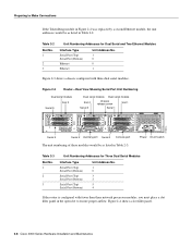
... port release screw Slot 1 Ethernet port Slot 2 Dual serial module H1033a Token Ring module Ethernet module Auxiliary port Console port Power On/off switch Slot Numbering The chassis contains slots for three network processor modules. The system console port, auxiliary (AUX) port, and network processor module ports appear to the left of the router chassis. Network...
... port release screw Slot 1 Ethernet port Slot 2 Dual serial module H1033a Token Ring module Ethernet module Auxiliary port Console port Power On/off switch Slot Numbering The chassis contains slots for three network processor modules. The system console port, auxiliary (AUX) port, and network processor module ports appear to the left of the router chassis. Network...
Hardware Maintenance Manual
Page 30
... 0 Console port The unit numbering of these modules would be as listed in Table 2-3. INPUT 100-240VAC 50/60HZ 3.0-1.5 AMPS Power On/off switch Table 2-3 Slot No. 1 2 3 Unit Numbering Addresses for Dual Serial and Two Ethernet Modules Interface Type Serial Port (Top) Serial Port...the Token Ring module in Figure 2-2 was replaced by a second Ethernet module, the unit addresses would be as listed in Table 2-2. H1402 a 2-8 Cisco 4000 Series Hardware Installation and Maintenance Table 2-2 Slot No. 1 2 3 Unit Numbering Addresses for Three Dual Serial Modules Interface Type Serial ...
... 0 Console port The unit numbering of these modules would be as listed in Table 2-3. INPUT 100-240VAC 50/60HZ 3.0-1.5 AMPS Power On/off switch Table 2-3 Slot No. 1 2 3 Unit Numbering Addresses for Dual Serial and Two Ethernet Modules Interface Type Serial Port (Top) Serial Port...the Token Ring module in Figure 2-2 was replaced by a second Ethernet module, the unit addresses would be as listed in Table 2-2. H1402 a 2-8 Cisco 4000 Series Hardware Installation and Maintenance Table 2-2 Slot No. 1 2 3 Unit Numbering Addresses for Three Dual Serial Modules Interface Type Serial ...

Hardware Maintenance Manual
Page 32
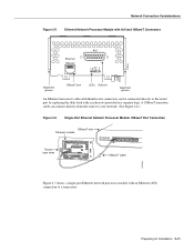
... software publications for more information on the module can be used at a time.) Use either an IEEE 802.3 AUI or a 10BaseT cable to configure your selection of AUI or 10BaseT on the Cisco 4500-M and Cisco 4700. Network Connection Considerations Network Connection Considerations...connector on the media command. 2-10 Cisco 4000 Series Hardware Installation and Maintenance Enter the media command in the router's configuration file to make the connection. Single-Port Ethernet Module Connections Each single-port Ethernet network processor module has an Ethernet AUI connector and a ...
... software publications for more information on the module can be used at a time.) Use either an IEEE 802.3 AUI or a 10BaseT cable to configure your selection of AUI or 10BaseT on the Cisco 4500-M and Cisco 4700. Network Connection Considerations Network Connection Considerations...connector on the media command. 2-10 Cisco 4000 Series Hardware Installation and Maintenance Enter the media command in the router's configuration file to make the connection. Single-Port Ethernet Module Connections Each single-port Ethernet network processor module has an Ethernet AUI connector and a ...
Hardware Maintenance Manual
Page 33
... Figure 2-6.) Figure 2-6 Single-Port Ethernet Network Processor Module 10BaseT Port Connection 10BaseT hub Ethernet module Router (rear view) AUI 10BASET AUX 10BaseT cable H1524a Figure 2-7 shows a single-port Ethernet network processor module with a jackscrew (provided in a separate bag). ...Preparing for Installation 2-11 Network Connection Considerations Figure 2-5 Ethernet Network Processor Module with AUI and 10BaseT Connectors AUI Ethernet 10BaseT TX ...
... Figure 2-6.) Figure 2-6 Single-Port Ethernet Network Processor Module 10BaseT Port Connection 10BaseT hub Ethernet module Router (rear view) AUI 10BASET AUX 10BaseT cable H1524a Figure 2-7 shows a single-port Ethernet network processor module with a jackscrew (provided in a separate bag). ...Preparing for Installation 2-11 Network Connection Considerations Figure 2-5 Ethernet Network Processor Module with AUI and 10BaseT Connectors AUI Ethernet 10BaseT TX ...
Hardware Maintenance Manual
Page 34
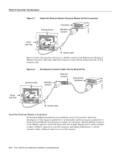
...for two network connections. (See Figure 2-9.) The top port is marked Port-0. On the dual-port Ethernet network processor module, on the module, and the lower port is marked Port-1 on a given port, either the Ethernet connector or the 10BaseT connector can... with a slide-latch connector to an AUI connector. 2-12 Cisco 4000 Series Hardware Installation and Maintenance Network Connection Considerations Router (rear view) Figure 2-7 Single-Port Ethernet Network Processor Module AUI Port Connection Ethernet module Transceiver Slide-latch connector H1525a AUI Router (rear view) AUX ...
...for two network connections. (See Figure 2-9.) The top port is marked Port-0. On the dual-port Ethernet network processor module, on the module, and the lower port is marked Port-1 on a given port, either the Ethernet connector or the 10BaseT connector can... with a slide-latch connector to an AUI connector. 2-12 Cisco 4000 Series Hardware Installation and Maintenance Network Connection Considerations Router (rear view) Figure 2-7 Single-Port Ethernet Network Processor Module AUI Port Connection Ethernet module Transceiver Slide-latch connector H1525a AUI Router (rear view) AUX ...
Hardware Maintenance Manual
Page 35
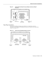
...ports DB-15 female Alignment groove Token Ring Connections The dual-port Token Ring network processor module has two standard 9-pin connectors. (See Figure 2-10.) The single-port Token Ring network processor module has one standard 9-pin connector. (See Figure 2-11.) Figure 2-10 Dual-Port ...Token Ring Module Network Connector Token Ring IN-RING B IN-RING A H1980 Alignment groove RING B RING A 16MBPS LEDs DB...
...ports DB-15 female Alignment groove Token Ring Connections The dual-port Token Ring network processor module has two standard 9-pin connectors. (See Figure 2-10.) The single-port Token Ring network processor module has one standard 9-pin connector. (See Figure 2-11.) Figure 2-10 Dual-Port ...Token Ring Module Network Connector Token Ring IN-RING B IN-RING A H1980 Alignment groove RING B RING A 16MBPS LEDs DB...
Hardware Maintenance Manual
Page 36
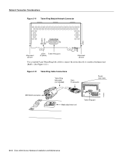
Network Connection Considerations Figure 2-11 Token Ring Module Network Connector 16MBPS IN-RING H1042a Token Ring Alignment groove LEDs Token Ring port (2 green) Alignment groove Use a standard 9-pin Token Ring lobe cable to connect the router directly to a media attachment unit (MAU). (See Figure 2-12.) Figure 2-12 Token Ring Cable Connections Token Ring lobe cable (not included) 9-pin D connector Router (rear view) H1569a IEEE 802.5 connector Media attachment unit Token Ring port 2-14 Cisco 4000 Series Hardware Installation and Maintenance
Network Connection Considerations Figure 2-11 Token Ring Module Network Connector 16MBPS IN-RING H1042a Token Ring Alignment groove LEDs Token Ring port (2 green) Alignment groove Use a standard 9-pin Token Ring lobe cable to connect the router directly to a media attachment unit (MAU). (See Figure 2-12.) Figure 2-12 Token Ring Cable Connections Token Ring lobe cable (not included) 9-pin D connector Router (rear view) H1569a IEEE 802.5 connector Media attachment unit Token Ring port 2-14 Cisco 4000 Series Hardware Installation and Maintenance

Hardware Maintenance Manual
Page 37
... the adapter cable is commonly used. Preparing for each serial interface type; However, do so at signal speeds up your own risk. however, the serial module ports support synchronous connections, and the console and auxiliary ports support asynchronous connections. Table 2-4 EIA/TIA-232 Distance Rate (bps) 2400 4800 9600 19200 38400...
... the adapter cable is commonly used. Preparing for each serial interface type; However, do so at signal speeds up your own risk. however, the serial module ports support synchronous connections, and the console and auxiliary ports support asynchronous connections. Table 2-4 EIA/TIA-232 Distance Rate (bps) 2400 4800 9600 19200 38400...