
Hardware Installation Guide
Page 3
...Fast Ethernet Switch Front Panel Descriptions 1-3 Gigabit Ethernet Switch Front Panel Descriptions 1-6 10/100 and 10/100/1000 Ports 1-8 PoE Ports 1-9 SFP Module Slots 1-10 SFP Modules 1-10 SFP Module Patch Cable 1-10 Dual-Purpose Port 1-10 LEDs 1-11 System LED 1-11 RPS LED 1-12 Port LEDs and Modes 1-13 ...Dual-Purpose Port LEDs 1-15 Cable Guard 1-15 Rear Panel Description 1-15 Internal Power Supply 1-18 DC Power Connector 1-18 Cisco RPS 1-19 Cisco RPS 2300 1-19 Cisco...
...Fast Ethernet Switch Front Panel Descriptions 1-3 Gigabit Ethernet Switch Front Panel Descriptions 1-6 10/100 and 10/100/1000 Ports 1-8 PoE Ports 1-9 SFP Module Slots 1-10 SFP Modules 1-10 SFP Module Patch Cable 1-10 Dual-Purpose Port 1-10 LEDs 1-11 System LED 1-11 RPS LED 1-12 Port LEDs and Modes 1-13 ...Dual-Purpose Port LEDs 1-15 Cable Guard 1-15 Rear Panel Description 1-15 Internal Power Supply 1-18 DC Power Connector 1-18 Cisco RPS 1-19 Cisco RPS 2300 1-19 Cisco...

Hardware Installation Guide
Page 4
...19 Connecting the Switch to Compatible Devices 2-20 Connecting to 10BASE-T or 100BASE-TX Devices 2-20 Connecting to Fiber-Optic SFP Modules 2-21 Connecting to 1000BASE-T SFP Modules 2-22 Connecting to a Dual-Purpose Port 2-23 Where to the Switch for Installation 3-1 Warnings 3-2 Installation Guidelines...RPS Connector Cover 2-13 Mounting the Switch on a Wall 2-14 Table- Mounting 2-15 Installing and Removing SFP Modules 2-15 Installing SFP Modules into SFP Module Slots 2-16 Removing SFP Modules from the Switch 2-8 Attaching Brackets to the Catalyst 3560 Switch 2-8 Mounting the Switch in a ...
...19 Connecting the Switch to Compatible Devices 2-20 Connecting to 10BASE-T or 100BASE-TX Devices 2-20 Connecting to Fiber-Optic SFP Modules 2-21 Connecting to 1000BASE-T SFP Modules 2-22 Connecting to a Dual-Purpose Port 2-23 Where to the Switch for Installation 3-1 Warnings 3-2 Installation Guidelines...RPS Connector Cover 2-13 Mounting the Switch on a Wall 2-14 Table- Mounting 2-15 Installing and Removing SFP Modules 2-15 Installing SFP Modules into SFP Module Slots 2-16 Removing SFP Modules from the Switch 2-8 Attaching Brackets to the Catalyst 3560 Switch 2-8 Mounting the Switch in a ...

Hardware Installation Guide
Page 6
Contents A A P P E N D I X B A P P E N D I X C A P P E N D I X D A P P E N D I X INDEX Technical Specifications A-1 Connector and Cable Specifications B-1 Connector Specifications B-1 10/100 and 10/100/1000 Ports B-1 SFP Module Ports B-2 Dual-Purpose Ports B-3 Console Port B-3 Cable and Adapter Specifications B-4 SFP Module Cable Specifications B-4 Two Twisted-Pair Cable Pinouts B-5 Four Twisted-Pair Cable Pinouts for 1000BASE-T Ports B-6 Identifying a Crossover Cable B-6 Adapter Pinouts B-7 Connecting to...
Contents A A P P E N D I X B A P P E N D I X C A P P E N D I X D A P P E N D I X INDEX Technical Specifications A-1 Connector and Cable Specifications B-1 Connector Specifications B-1 10/100 and 10/100/1000 Ports B-1 SFP Module Ports B-2 Dual-Purpose Ports B-3 Console Port B-3 Cable and Adapter Specifications B-4 SFP Module Cable Specifications B-4 Two Twisted-Pair Cable Pinouts B-5 Four Twisted-Pair Cable Pinouts for 1000BASE-T Ports B-6 Identifying a Crossover Cable B-6 Adapter Pinouts B-7 Connecting to...
Hardware Installation Guide
Page 8
... This warning symbol means danger. You are available from this Cisco.com site: http://www.cisco.com/en/US/products/hw/modules/ps5455/products_device_support_tables_list.html • Cisco Gigabit Ethernet Transceiver Modules Compatibility Matrix • Cisco 100-Megabit Ethernet SFP Modules Compatibility Matrix • Cisco CWDM SFP Transceiver Compatibility Matrix Catalyst 3560 Switch Hardware Installation Guide viii OL...
... This warning symbol means danger. You are available from this Cisco.com site: http://www.cisco.com/en/US/products/hw/modules/ps5455/products_device_support_tables_list.html • Cisco Gigabit Ethernet Transceiver Modules Compatibility Matrix • Cisco 100-Megabit Ethernet SFP Modules Compatibility Matrix • Cisco CWDM SFP Transceiver Compatibility Matrix Catalyst 3560 Switch Hardware Installation Guide viii OL...

Hardware Installation Guide
Page 12
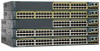
... (only Catalyst 3560 24- and 48-port switches) • 1000BASE-ZX • Coarse Wavelength-Division Multiplexing (CWDM) • SFP module patch cable. (CAB-SFP-50CM=.) Switches running Cisco IOS Release 12.2(25)SEB or later support this patch cable. They can be mounted with a magnet, have security lock slots, ...) ports and 2 small form-factor pluggable (SFP) module slots Catalyst 3560-24TS-S 24 10/100 ports and 2 SFP module slots Catalyst 3560-48PS 48 10/100 PoE ports and 4 SFP module slots Catalyst 3560-48TS-S 48 10/100 ports and 4 SFP module slots Catalyst 3560V2-24PS 24 10/100 PoE...
... (only Catalyst 3560 24- and 48-port switches) • 1000BASE-ZX • Coarse Wavelength-Division Multiplexing (CWDM) • SFP module patch cable. (CAB-SFP-50CM=.) Switches running Cisco IOS Release 12.2(25)SEB or later support this patch cable. They can be mounted with a magnet, have security lock slots, ...) ports and 2 small form-factor pluggable (SFP) module slots Catalyst 3560-24TS-S 24 10/100 ports and 2 SFP module slots Catalyst 3560-48PS 48 10/100 PoE ports and 4 SFP module slots Catalyst 3560-48TS-S 48 10/100 ports and 4 SFP module slots Catalyst 3560V2-24PS 24 10/100 PoE...

Hardware Installation Guide
Page 13
...; Gigabit Ethernet Switch Front Panel Descriptions, page 1-6 • 10/100 and 10/100/1000 Ports, page 1-8 • PoE Ports, page 1-9 • SFP Module Slots, page 1-10 • Dual-Purpose Port, page 1-10 • LEDs, page 1-11 • Cable Guard, page 1-15 Fast Ethernet Switch... Front Panel Descriptions • Catalyst 3560-24PS and 3560V2-24PS Switch Front Panel, Figure 1-1 on page 1-3 • Catalyst 3560-24TS-S, 3560V2-24TS, and 3560V2-24TS-SD Switch Front Panel, Figure 1-2 on page 1-4 • Catalyst 3560-48PS and 3560V2-48PS Switch Front Panel, Figure 1-3 on page ...
...; Gigabit Ethernet Switch Front Panel Descriptions, page 1-6 • 10/100 and 10/100/1000 Ports, page 1-8 • PoE Ports, page 1-9 • SFP Module Slots, page 1-10 • Dual-Purpose Port, page 1-10 • LEDs, page 1-11 • Cable Guard, page 1-15 Fast Ethernet Switch... Front Panel Descriptions • Catalyst 3560-24PS and 3560V2-24PS Switch Front Panel, Figure 1-1 on page 1-3 • Catalyst 3560-24TS-S, 3560V2-24TS, and 3560V2-24TS-SD Switch Front Panel, Figure 1-2 on page 1-4 • Catalyst 3560-48PS and 3560V2-48PS Switch Front Panel, Figure 1-3 on page ...

Hardware Installation Guide
Page 14
...24TS, and 3560V2-24TS-SD Switch Front Panel 126808 SYST RPS STAT DUPLX SPEED MODE 12 1X 34 56 78 9 10 11 12 11X 2X 12X 13 14 13X 15 16 17 18 19 20 21 22 23 24 23X Catalyst 3560 SERIES 14X 24X 1 2 1 2 1 10/100 ports 2 SFP... 10/100 ports on the switch are grouped in pairs. The SFP module slots are numbered 1 to 4. The SFP module slots are numbered 1 and 2. Figure 1-3 Catalyst 3560-48PS...SERIES PoE-48 47X 32X 34X 1 3 48X 2 4 1 2 1 10/100 PoE ports 2 SFP module slots Catalyst 3560 Switch Hardware Installation Guide 1-4 OL-6337-07 Port 3 is above port 4, ...
...24TS, and 3560V2-24TS-SD Switch Front Panel 126808 SYST RPS STAT DUPLX SPEED MODE 12 1X 34 56 78 9 10 11 12 11X 2X 12X 13 14 13X 15 16 17 18 19 20 21 22 23 24 23X Catalyst 3560 SERIES 14X 24X 1 2 1 2 1 10/100 ports 2 SFP... 10/100 ports on the switch are grouped in pairs. The SFP module slots are numbered 1 to 4. The SFP module slots are numbered 1 and 2. Figure 1-3 Catalyst 3560-48PS...SERIES PoE-48 47X 32X 34X 1 3 48X 2 4 1 2 1 10/100 PoE ports 2 SFP module slots Catalyst 3560 Switch Hardware Installation Guide 1-4 OL-6337-07 Port 3 is above port 4, ...

Hardware Installation Guide
Page 15
...07 Catalyst 3560 Switch Hardware Installation Guide 1-5 For more information on the console port, see the "Dual-Purpose Port" section on page 1-10. The SFP module slots are grouped in Figure 1-4. Figure 1-4 Catalyst 3560-48TS-S and 3560V2-48TS Switch Front Panel 126807 SYST RPS STAT DUPLX SPEED MODE 1 1X...is above the second member (port 2) on the switch are numbered 1 to 4. The dual-purpose port can use either an RJ-45 connector or an SFP module, but not both at the same time. For more information on the dual-purpose port, see the "Console Port" section on . Chapter 1 Product...
...07 Catalyst 3560 Switch Hardware Installation Guide 1-5 For more information on the console port, see the "Dual-Purpose Port" section on page 1-10. The SFP module slots are grouped in Figure 1-4. Figure 1-4 Catalyst 3560-48TS-S and 3560V2-48TS Switch Front Panel 126807 SYST RPS STAT DUPLX SPEED MODE 1 1X...is above the second member (port 2) on the switch are numbered 1 to 4. The dual-purpose port can use either an RJ-45 connector or an SFP module, but not both at the same time. For more information on the dual-purpose port, see the "Console Port" section on . Chapter 1 Product...

Hardware Installation Guide
Page 16
... ports 3 Dual-purpose port Gigabit Ethernet Switch Front Panel Descriptions • Catalyst 3560G-24PS Switch Front Panel, Figure 1-7 on page 1-6 • Catalyst 3560G-24TS Switch Front Panel, Figure 1-8 on page 1-7 • Catalyst 3560G-48PS Switch Front Panel, Figure 1-9 on page 1-7 • Catalyst 3560G-48TS Switch Front... Panel, Figure 1-10 on page 1-8 The 10/100/1000 PoE ports on the left, as shown in pairs. The SFP module slots are grouped in Figure 1-7. Figure 1-7 Catalyst 3560G-24PS Switch Front Panel 119676 SYST RPS STAT DUPLX SPEED PoE MODE 12 1X ...
... ports 3 Dual-purpose port Gigabit Ethernet Switch Front Panel Descriptions • Catalyst 3560G-24PS Switch Front Panel, Figure 1-7 on page 1-6 • Catalyst 3560G-24TS Switch Front Panel, Figure 1-8 on page 1-7 • Catalyst 3560G-48PS Switch Front Panel, Figure 1-9 on page 1-7 • Catalyst 3560G-48TS Switch Front... Panel, Figure 1-10 on page 1-8 The 10/100/1000 PoE ports on the left, as shown in pairs. The SFP module slots are grouped in Figure 1-7. Figure 1-7 Catalyst 3560G-24PS Switch Front Panel 119676 SYST RPS STAT DUPLX SPEED PoE MODE 12 1X ...

Hardware Installation Guide
Page 17
...24TS Switch Front Panel 119677 SYST RPS STAT DUPLX SPEED MODE 12 1X 34 56 78 9 10 11 12 11X 2X 12X 13 14 13X 15 16 17 18 19 20 21 22 23 24 23X Catalyst 3560G SERIES 25 14X 27 24X 26 28 1 2 1 10/100/1000 ports 2 SFP... module slots The 10/100/1000 PoE ports on the Catalyst 3560-24TS switch are grouped in pairs. Figure 1-9 Catalyst 3560G-48PS ... Installation Guide 1-7 Port 3 is above port 4, and so on . The SFP module slots are numbered 49 to 28. The SFP module slots are numbered 25 to 52. Port 3 is above port 4, and...
...24TS Switch Front Panel 119677 SYST RPS STAT DUPLX SPEED MODE 12 1X 34 56 78 9 10 11 12 11X 2X 12X 13 14 13X 15 16 17 18 19 20 21 22 23 24 23X Catalyst 3560G SERIES 25 14X 27 24X 26 28 1 2 1 10/100/1000 ports 2 SFP... module slots The 10/100/1000 PoE ports on the Catalyst 3560-24TS switch are grouped in pairs. Figure 1-9 Catalyst 3560G-48PS ... Installation Guide 1-7 Port 3 is above port 4, and so on . The SFP module slots are numbered 49 to 28. The SFP module slots are numbered 25 to 52. Port 3 is above port 4, and...

Hardware Installation Guide
Page 18
... 1-10. You can set for speed and duplex autonegotiation, in any combination of the hazard. Catalyst 3560 Switch Hardware Installation Guide 1-8 OL-6337-07 The SFP module slots are numbered 49 to operate in compliance with IEEE 802.3ab. (The default setting is autonegotiate.) • You can set the 10/100... 39 40 41 42 43 44 45 46 47 48 47X 32X 34X Catalyst 3560G SERIES 49 51 48X 50 52 1 2 1 10/100/1000 ports 2 SFP module slots 10/100 and 10/100/1000 Ports • You can set both devices support and full-duplex transmission if the attached device supports...
... 1-10. You can set for speed and duplex autonegotiation, in any combination of the hazard. Catalyst 3560 Switch Hardware Installation Guide 1-8 OL-6337-07 The SFP module slots are numbered 49 to operate in compliance with IEEE 802.3ab. (The default setting is autonegotiate.) • You can set the 10/100... 39 40 41 42 43 44 45 46 47 48 47X 32X 34X Catalyst 3560G SERIES 49 51 48X 50 52 1 2 1 10/100/1000 ports 2 SFP module slots 10/100 and 10/100/1000 Ports • You can set both devices support and full-duplex transmission if the attached device supports...

Hardware Installation Guide
Page 19
...average of 7.7 W of PoE at the same time, up to the AC power source as an IEEE 802.3af-compliant powered device, a Cisco prestandard IP phone, or a Cisco prestandard Cisco access point, is enabled by default. During the power transfer, an IP phone might change to 15.4 W of the connection. Pinouts for.... If the primary source fails, the second power source becomes the primary power source to a copper 10/100, 10/100/1000, or 1000BASE-T SFP module port on the switch, regardless of the type of device on the other end of PoE. OL-6337-07 Catalyst 3560 Switch Hardware Installation...
...average of 7.7 W of PoE at the same time, up to the AC power source as an IEEE 802.3af-compliant powered device, a Cisco prestandard IP phone, or a Cisco prestandard Cisco access point, is enabled by default. During the power transfer, an IP phone might change to 15.4 W of the connection. Pinouts for.... If the primary source fails, the second power source becomes the primary power source to a copper 10/100, 10/100/1000, or 1000BASE-T SFP module port on the switch, regardless of the type of device on the other end of PoE. OL-6337-07 Catalyst 3560 Switch Hardware Installation...

Hardware Installation Guide
Page 20
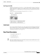
... connections. Figure 1-11 SFP Module Patch Cable 126809 The SFP module patch cable can...or the SFP module connector. Each port...SFP modules. The switch activates only one shows the status of the pair at each end (see your SFP...SFP module port. To connect a Catalyst 3560 switch to other Catalyst series switches, you can use the SFP modules specified in an SFP... module slot. The dual front ends are field-replaceable, providing uplink interfaces when inserted in the "SFP... RJ-45 connector and an SFP module connector. SFP Module Slots See the release...
... connections. Figure 1-11 SFP Module Patch Cable 126809 The SFP module patch cable can...or the SFP module connector. Each port...SFP modules. The switch activates only one shows the status of the pair at each end (see your SFP...SFP module port. To connect a Catalyst 3560 switch to other Catalyst series switches, you can use the SFP modules specified in an SFP... module slot. The dual front ends are field-replaceable, providing uplink interfaces when inserted in the "SFP... RJ-45 connector and an SFP module connector. SFP Module Slots See the release...

Hardware Installation Guide
Page 23
... also change a mode, press the Mode button until the desired mode is the default mode. This is highlighted. When installed in Catalyst 3560 switches, 1000BASE-T SFP modules can operate at 10, 100, or 1000 Mb/s in half-duplex mode. Table 1-5 PoE Mode LED Color Off Green Blinking amber PoE Status PoE...
... also change a mode, press the Mode button until the desired mode is the default mode. This is highlighted. When installed in Catalyst 3560 switches, 1000BASE-T SFP modules can operate at 10, 100, or 1000 Mb/s in half-duplex mode. Table 1-5 PoE Mode LED Color Off Green Blinking amber PoE Status PoE...

Hardware Installation Guide
Page 24
...PoE is operating at 10 Mb/s. Off No link, or port was administratively shut down. Error frames can remain amber for possible loops. SFP ports Off Port is off due to 30 seconds as excessive collisions, cyclic redundancy check (CRC) errors, and alignment and jabber errors are... connected to PoE ports. Note When installed in Catalyst 3560 switches, 1000BASE-T SFP modules can be used to connect Cisco prestandard IP Phones or wireless access points or IEEE 802.3af-compliant devices to a PoE port. Amber PoE for a link-fault...
...PoE is operating at 10 Mb/s. Off No link, or port was administratively shut down. Error frames can remain amber for possible loops. SFP ports Off Port is off due to 30 seconds as excessive collisions, cyclic redundancy check (CRC) errors, and alignment and jabber errors are... connected to PoE ports. Note When installed in Catalyst 3560 switches, 1000BASE-T SFP modules can be used to connect Cisco prestandard IP Phones or wireless access points or IEEE 802.3af-compliant devices to a PoE port. Amber PoE for a link-fault...
Hardware Installation Guide
Page 25
... guard (CBLGRD-C3560-12PC or CBLGRD-C3560-8PC), contact your Cisco representative. The switch console port is on page 2-11). Figure 1-13 Dual-Purpose Port LEDs 1 234 1 1 RJ-45 connector 3 SFP module port LED 2 RJ-45 port LED 4 SFP module slot Cable Guard You can configure each port as either ...installed. You can order an optional cable guard to secure cables to Table 1-6. Rear Panel Description • Internal Power Supply, page 1-18 • Cisco RPS, page 1-19 • Console Port, page 1-19 • Security Slots, page 1-20 Note The Catalyst 3560-8PC and the Catalyst 3560-12PC...
... guard (CBLGRD-C3560-12PC or CBLGRD-C3560-8PC), contact your Cisco representative. The switch console port is on page 2-11). Figure 1-13 Dual-Purpose Port LEDs 1 234 1 1 RJ-45 connector 3 SFP module port LED 2 RJ-45 port LED 4 SFP module slot Cable Guard You can configure each port as either ...installed. You can order an optional cable guard to secure cables to Table 1-6. Rear Panel Description • Internal Power Supply, page 1-18 • Cisco RPS, page 1-19 • Console Port, page 1-19 • Security Slots, page 1-20 Note The Catalyst 3560-8PC and the Catalyst 3560-12PC...
Hardware Installation Guide
Page 33
...switch. and 12-Port Switches)." 2 C H A P T E R Switch Installation (24- For installation information for installing, and connecting to the SFP modules apply to the switch ports and for the Catalyst 3560-8PC and Catalyst 3560 12-PC-S switches, see Chapter 3, "Switch Installation (8- The instructions... page 2-1 • Verifying Switch Operation, page 2-6 • Installing the Switch, page 2-7 • Installing and Removing SFP Modules, page 2-15 • Inserting and Removing the SFP Module Patch Cable, page 2-18 • 10/100 or 10/100/1000 Ports, page 2-19 • Connecting the ...
...switch. and 12-Port Switches)." 2 C H A P T E R Switch Installation (24- For installation information for installing, and connecting to the SFP modules apply to the switch ports and for the Catalyst 3560-8PC and Catalyst 3560 12-PC-S switches, see Chapter 3, "Switch Installation (8- The instructions... page 2-1 • Verifying Switch Operation, page 2-6 • Installing the Switch, page 2-7 • Installing and Removing SFP Modules, page 2-15 • Inserting and Removing the SFP Module Patch Cable, page 2-18 • 10/100 or 10/100/1000 Ports, page 2-19 • Connecting the ...

Hardware Installation Guide
Page 37
...overloading the receiver. Note The grounding architecture of electrical noise, such as radios, power lines, and fluorescent lighting fixtures. Catalyst 3560 switch SFP ports use shorter lengths of an AC power receptacle. • Temperature around it might damage the cables. • For copper Ethernet ports..., including 10/100 ports, 10/100/1000 ports, and 1000BASE-T SFP module ports, cable lengths from sources of this product is within reach of single-mode fiber cable, you determine where to place the ...
...overloading the receiver. Note The grounding architecture of electrical noise, such as radios, power lines, and fluorescent lighting fixtures. Catalyst 3560 switch SFP ports use shorter lengths of an AC power receptacle. • Temperature around it might damage the cables. • For copper Ethernet ports..., including 10/100 ports, 10/100/1000 ports, and 1000BASE-T SFP module ports, cable lengths from sources of this product is within reach of single-mode fiber cable, you determine where to place the ...

Hardware Installation Guide
Page 38
... acceptable levels of the link. • Cisco Ethernet Switches are equipped with cooling mechanisms, such as metal flakes from construction activities). Verifying Switch Operation Chapter 2 Switch Installation (24- To power on the switch, connect one SFP module slot) Box Contents The switch getting ...started guide on the 1000BASE-ZX SFP module at each end of suspended particulate matter: - If your Cisco representative or reseller for more information. Set the RPS to the...
... acceptable levels of the link. • Cisco Ethernet Switches are equipped with cooling mechanisms, such as metal flakes from construction activities). Verifying Switch Operation Chapter 2 Switch Installation (24- To power on the switch, connect one SFP module slot) Box Contents The switch getting ...started guide on the 1000BASE-ZX SFP module at each end of suspended particulate matter: - If your Cisco representative or reseller for more information. Set the RPS to the...
Hardware Installation Guide
Page 47
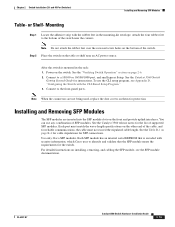
...Setup. Note When the connectors are inserted into the SFP module slots on the bottom of the switch. To use any combination of supported SFP modules. See the Catalyst 3560 release notes for SFP connections. Use only Cisco SFP modules. For detailed instructions on them for the switch.... and 48-Port Switches) Installing and Removing SFP Modules Table- Attach the four rubber feet ...
...Setup. Note When the connectors are inserted into the SFP module slots on the bottom of the switch. To use any combination of supported SFP modules. See the Catalyst 3560 release notes for SFP connections. Use only Cisco SFP modules. For detailed instructions on them for the switch.... and 48-Port Switches) Installing and Removing SFP Modules Table- Attach the four rubber feet ...

