
Hardware Installation Guide
Page 3
... RPS LED 1-12 Port LEDs and Modes 1-13 Dual-Purpose Port LEDs 1-15 Cable Guard 1-15 Rear Panel Description 1-15 Internal Power Supply 1-18 DC Power Connector 1-18 Cisco RPS 1-19 Cisco RPS 2300 1-19 Cisco RPS 675 1-19 Console Port 1-19 Security Slots 1-20 Management Options 1-20 Catalyst 3560 Switch Hardware Installation Guide iii
... RPS LED 1-12 Port LEDs and Modes 1-13 Dual-Purpose Port LEDs 1-15 Cable Guard 1-15 Rear Panel Description 1-15 Internal Power Supply 1-18 DC Power Connector 1-18 Cisco RPS 1-19 Cisco RPS 2300 1-19 Cisco RPS 675 1-19 Console Port 1-19 Security Slots 1-20 Management Options 1-20 Catalyst 3560 Switch Hardware Installation Guide iii

Hardware Installation Guide
Page 4
and 48-Port Switches) 2-1 Preparing for Installation 2-1 Warnings 2-2 Installation Guidelines 2-5 Box Contents 2-6 Tools and Equipment 2-6 Verifying Switch Operation 2-6 Powering Off the Switch 2-7 Installing the Switch 2-7 Rack-Mounting 2-7 Removing Screws from SFP Module Slots 2-17 Inserting and Removing the SFP Module Patch Cable 2-18 10/...
and 48-Port Switches) 2-1 Preparing for Installation 2-1 Warnings 2-2 Installation Guidelines 2-5 Box Contents 2-6 Tools and Equipment 2-6 Verifying Switch Operation 2-6 Powering Off the Switch 2-7 Installing the Switch 2-7 Rack-Mounting 2-7 Removing Screws from SFP Module Slots 2-17 Inserting and Removing the SFP Module Patch Cable 2-18 10/...
Hardware Installation Guide
Page 5
4 C H A P T E R Box Contents 3-7 Tools and Equipment 3-7 Verifying Switch Operation 3-7 Powering Off the Switch 3-7 Installing the Switch 3-7 Desk or Shelf Mounting 3-8 Desk or Shelf Mounting (Unsecured) 3-8 Desk or Shelf Mounting (Secured) 3-8 Under the Desk ... 3-16 Attaching Brackets to the Switch 3-16 Mounting the Switch in a 19-Inch Rack 3-17 Wall-Mounting (with Rack-Mount Brackets) 3-17 Securing the AC Power Cord 3-19 Where to Go Next 3-20 Troubleshooting 4-1 Diagnosing Problems 4-1 Evaluate Switch POST Results 4-2 Monitor Switch LEDs 4-2 Verify Switch Connections 4-2 Bad or Damaged Cable ...
4 C H A P T E R Box Contents 3-7 Tools and Equipment 3-7 Verifying Switch Operation 3-7 Powering Off the Switch 3-7 Installing the Switch 3-7 Desk or Shelf Mounting 3-8 Desk or Shelf Mounting (Unsecured) 3-8 Desk or Shelf Mounting (Secured) 3-8 Under the Desk ... 3-16 Attaching Brackets to the Switch 3-16 Mounting the Switch in a 19-Inch Rack 3-17 Wall-Mounting (with Rack-Mount Brackets) 3-17 Securing the AC Power Cord 3-19 Where to Go Next 3-20 Troubleshooting 4-1 Diagnosing Problems 4-1 Evaluate Switch POST Results 4-2 Monitor Switch LEDs 4-2 Verify Switch Connections 4-2 Bad or Damaged Cable ...

Hardware Installation Guide
Page 6
... Cable Pinouts B-5 Four Twisted-Pair Cable Pinouts for 1000BASE-T Ports B-6 Identifying a Crossover Cable B-6 Adapter Pinouts B-7 Connecting to DC Power C-1 Connecting to DC Power C-1 Preparing for Installation C-2 Grounding the Switch C-2 Wiring the DC-Input Power Source C-5 Configuring the Switch with the CLI-Based Setup Program D-1 Preparing for Setup D-1 Completing the Setup Program D-3 Catalyst 3560...
... Cable Pinouts B-5 Four Twisted-Pair Cable Pinouts for 1000BASE-T Ports B-6 Identifying a Crossover Cable B-6 Adapter Pinouts B-7 Connecting to DC Power C-1 Connecting to DC Power C-1 Preparing for Installation C-2 Grounding the Switch C-2 Wiring the DC-Input Power Source C-5 Configuring the Switch with the CLI-Based Setup Program D-1 Preparing for Setup D-1 Completing the Setup Program D-3 Catalyst 3560...
Hardware Installation Guide
Page 8
... the end of the hazards involved with Cisco Network Assistant • Release Notes for Cisco Network Assistant • Cisco Small Form-Factor Pluggable Modules Installation Notes • Cisco CWDM GBIC and CWDM SFP Installation Note • Cisco RPS 2300 Redundant Power System Hardware Installation Guide • Cisco RPS 675 Redundant Power System Hardware Installation Guide These compatibility matrix...
... the end of the hazards involved with Cisco Network Assistant • Release Notes for Cisco Network Assistant • Cisco Small Form-Factor Pluggable Modules Installation Notes • Cisco CWDM GBIC and CWDM SFP Installation Note • Cisco RPS 2300 Redundant Power System Hardware Installation Guide • Cisco RPS 675 Redundant Power System Hardware Installation Guide These compatibility matrix...

Hardware Installation Guide
Page 11
... 100BASE-TX Ethernet traffic from other network devices. The getting started guide provides switch management options, basic rack-mounting procedures, port and module connections, power connection procedures, and troubleshooting help. Product Overview 1 C H A P T E R The Catalyst 3560 switch-also referred to as the switch-is... 2300 or Cisco RPS 675 that operates on how to use Express Setup to initially configure your switch using the command-line interface (CLI), see Appendix D, "Configuring the Switch with the CLI-Based Setup Program." For power redundancy, all but the Catalyst 3560 8- ...
... 100BASE-TX Ethernet traffic from other network devices. The getting started guide provides switch management options, basic rack-mounting procedures, port and module connections, power connection procedures, and troubleshooting help. Product Overview 1 C H A P T E R The Catalyst 3560 switch-also referred to as the switch-is... 2300 or Cisco RPS 675 that operates on how to use Express Setup to initially configure your switch using the command-line interface (CLI), see Appendix D, "Configuring the Switch with the CLI-Based Setup Program." For power redundancy, all but the Catalyst 3560 8- ...

Hardware Installation Guide
Page 12
...port switches) • 1000BASE-ZX • Coarse Wavelength-Division Multiplexing (CWDM) • SFP module patch cable. (CAB-SFP-50CM=.) Switches running Cisco IOS Release 12.2(25)SEB or later support this patch cable. Features Chapter 1 Product Overview Table 1-1 Catalyst 3560 Switch Model Descriptions Switch Model Description...ports and 4 SFP module slots Catalyst 3560V2-48TS 48 10/100 ports and 4 SFP module slots Catalyst 3560V2-24TS-SD 24 10/100 PoE ports and 2 SFP module slots (DC power) Catalyst 3560-8PC1 8 10/100 PoE ports and 1 dual-purpose port (one 10/100/1000BASE-T copper ...
...port switches) • 1000BASE-ZX • Coarse Wavelength-Division Multiplexing (CWDM) • SFP module patch cable. (CAB-SFP-50CM=.) Switches running Cisco IOS Release 12.2(25)SEB or later support this patch cable. Features Chapter 1 Product Overview Table 1-1 Catalyst 3560 Switch Model Descriptions Switch Model Description...ports and 4 SFP module slots Catalyst 3560V2-48TS 48 10/100 ports and 4 SFP module slots Catalyst 3560V2-24TS-SD 24 10/100 PoE ports and 2 SFP module slots (DC power) Catalyst 3560-8PC1 8 10/100 PoE ports and 1 dual-purpose port (one 10/100/1000BASE-T copper ...

Hardware Installation Guide
Page 18
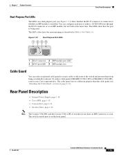
.../s. If the connected device also supports autonegotiation, the switch port negotiates the best connection (the fastest line speed that present a shock hazard may exist on Power over Ethernet (PoE) circuits if interconnections are made using uninsulated exposed metal contacts, conductors, or terminals. Front Panel Description Chapter 1 Product Overview The 10/100...
.../s. If the connected device also supports autonegotiation, the switch port negotiates the best connection (the fastest line speed that present a shock hazard may exist on Power over Ethernet (PoE) circuits if interconnections are made using uninsulated exposed metal contacts, conductors, or terminals. Front Panel Description Chapter 1 Product Overview The 10/100...

Hardware Installation Guide
Page 19
... ports or the Catalyst 3560G-24PS switch 10/100/1000 ports deliver up to a maximum power output of approximately 125 W total PoE power. • On a per-port basis, you can connect a Cisco IP Phone or Cisco Aironet Access Point to a Catalyst 3560 PoE switch 10/100 or 10/100/1000 port ...cable type for each 10/100 or 10/100/1000 PoE port: - During the power transfer, an IP phone might change to the AC power source as an IEEE 802.3af-compliant powered device, a Cisco prestandard IP phone, or a Cisco prestandard Cisco access point, is the default. - If the primary source fails, the second...
... ports or the Catalyst 3560G-24PS switch 10/100/1000 ports deliver up to a maximum power output of approximately 125 W total PoE power. • On a per-port basis, you can connect a Cisco IP Phone or Cisco Aironet Access Point to a Catalyst 3560 PoE switch 10/100 or 10/100/1000 port ...cable type for each 10/100 or 10/100/1000 PoE port: - During the power transfer, an IP phone might change to the AC power source as an IEEE 802.3af-compliant powered device, a Cisco prestandard IP phone, or a Cisco prestandard Cisco access point, is the default. - If the primary source fails, the second...

Hardware Installation Guide
Page 20
... (see the software configuration guide. The port LED is considered as an SFP module port. Front Panel Description Chapter 1 Product Overview Many legacy powered devices, including older Cisco IP phones and access points that first links up. SFP Module Slots See the release notes for more information about configuring speed and duplex...
... (see the software configuration guide. The port LED is considered as an SFP module port. Front Panel Description Chapter 1 Product Overview Many legacy powered devices, including older Cisco IP phones and access points that first links up. SFP Module Slots See the release notes for more information about configuring speed and duplex...

Hardware Installation Guide
Page 21
...Switch Operation" section on . The Catalyst 3560-8PC and the Catalyst 3560-12PC-S switches do not have an RPS LED. System is receiving power but is operating normally. Table 1-2 Color Off Green Amber System LED System Status System is only on the Catalyst 3560 PoE switches. 2. The... PoE LED is not powered on page 2-6. Chapter 1 Product Overview Front Panel Description LEDs You can use the switch LEDs to configure and monitor individual switches and switch clusters...
...Switch Operation" section on . The Catalyst 3560-8PC and the Catalyst 3560-12PC-S switches do not have an RPS LED. System is receiving power but is operating normally. Table 1-2 Color Off Green Amber System LED System Status System is only on the Catalyst 3560 PoE switches. 2. The... PoE LED is not powered on page 2-6. Chapter 1 Product Overview Front Panel Description LEDs You can use the switch LEDs to configure and monitor individual switches and switch clusters...
Hardware Installation Guide
Page 22
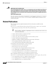
... RPS LED Color Off Green Blinking green Amber Blinking amber RPS Status RPS is providing power to another device (redundancy has been allocated to a neighboring device). Contact Cisco. The internal power supply in a fault condition. Note The Catalyst 3560-8PC and Catalyst 3560-12PC-S ... is off or not properly connected. For more information about the Cisco RPS 2300 and the RPS 675, see the Cisco Redundant Power System 2300 Hardware Installation Guide and the Cisco RPS 675 Redundant Power System Hardware Installation Guide. 1-12 Catalyst 3560 Switch Hardware Installation Guide...
... RPS LED Color Off Green Blinking green Amber Blinking amber RPS Status RPS is providing power to another device (redundancy has been allocated to a neighboring device). Contact Cisco. The internal power supply in a fault condition. Note The Catalyst 3560-8PC and Catalyst 3560-12PC-S ... is off or not properly connected. For more information about the Cisco RPS 2300 and the RPS 675, see the Cisco Redundant Power System 2300 Hardware Installation Guide and the Cisco RPS 675 Redundant Power System Hardware Installation Guide. 1-12 Catalyst 3560 Switch Hardware Installation Guide...

Hardware Installation Guide
Page 23
... PoE LED shows PoE problems when they are in half-duplex mode. OL-6337-07 Catalyst 3560 Switch Hardware Installation Guide 1-13 PoE PoE port power The PoE status. 1. The port operating speed: 10, 100, or 10001 Mb/s. When installed in Catalyst 3560 switches, 1000BASE-T SFP modules can operate at 10... ports has a PoE fault. PoE mode is not selected. At least one of the 10/100 or 10/100/1000 PoE ports has been denied power, or at 10 or 100 Mb/s in a fault condition. The PoE LED applies only to interpret the port LED colors in different port modes. Table...
... PoE LED shows PoE problems when they are in half-duplex mode. OL-6337-07 Catalyst 3560 Switch Hardware Installation Guide 1-13 PoE PoE port power The PoE status. 1. The port operating speed: 10, 100, or 10001 Mb/s. When installed in Catalyst 3560 switches, 1000BASE-T SFP modules can operate at 10... ports has a PoE fault. PoE mode is not selected. At least one of the 10/100 or 10/100/1000 PoE ports has been denied power, or at 10 or 100 Mb/s in a fault condition. The PoE LED applies only to interpret the port LED colors in different port modes. Table...

Hardware Installation Guide
Page 24
... or port was administratively shut down. You must remove from an AC power source, the PoE port LED is operating at 10 Mb/s. Blinking green Activity. Error frames can be used to connect Cisco prestandard IP Phones or wireless access points or IEEE 802.3af-compliant devices ...to 30 seconds as excessive collisions, cyclic redundancy check (CRC) errors, and alignment and jabber errors are connected to the powered device will exceed the 370 W switch power capacity. Only ...
... or port was administratively shut down. You must remove from an AC power source, the PoE port LED is operating at 10 Mb/s. Blinking green Activity. Error frames can be used to connect Cisco prestandard IP Phones or wireless access points or IEEE 802.3af-compliant devices ...to 30 seconds as excessive collisions, cyclic redundancy check (CRC) errors, and alignment and jabber errors are connected to the powered device will exceed the 370 W switch power capacity. Only ...
Hardware Installation Guide
Page 25
Rear Panel Description • Internal Power Supply, page 1-18 • Cisco RPS, page 1-19 • Console Port, page 1-19 • Security Slots, page 1-20 Note The Catalyst 3560-8PC and the Catalyst 3560-12PC-S switches do ... cables to Table 1-6. The LED colors have an RPS connector or a fan. To order a cable guard (CBLGRD-C3560-12PC or CBLGRD-C3560-8PC), contact your Cisco representative. The switch console port is installed.
Rear Panel Description • Internal Power Supply, page 1-18 • Cisco RPS, page 1-19 • Console Port, page 1-19 • Security Slots, page 1-20 Note The Catalyst 3560-8PC and the Catalyst 3560-12PC-S switches do ... cables to Table 1-6. The LED colors have an RPS connector or a fan. To order a cable guard (CBLGRD-C3560-12PC or CBLGRD-C3560-8PC), contact your Cisco representative. The switch console port is installed.
Hardware Installation Guide
Page 26
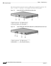
Rear Panel Description Chapter 1 Product Overview The switch rear panel has an AC power connector, an RPS connector, and an RJ-45 console port. (See Figure 1-14, Figure 1-15, and Figure 1-16 for examples...,0IN500GV-6~0 HZ [email protected]@YMUO7A.TL8EA 97914 1 2 3 4 1 RJ-45 console port 3 RPS connector 2 AC power connector 4 Fan exhaust Figure 1-15 Catalyst 3560G-24PS, 3560G-48PS, 3560G-24TS, and 3560G-48TS Switch Rear Panel 119678 CONSOLE DSCPIENPCPOIUWFTIEESDRFISONURMPRPAELNYMUOATLE 12 3 4 1 RJ-45 console port 3 RPS connector 2 Fan exhaust 4...
Rear Panel Description Chapter 1 Product Overview The switch rear panel has an AC power connector, an RPS connector, and an RJ-45 console port. (See Figure 1-14, Figure 1-15, and Figure 1-16 for examples...,0IN500GV-6~0 HZ [email protected]@YMUO7A.TL8EA 97914 1 2 3 4 1 RJ-45 console port 3 RPS connector 2 AC power connector 4 Fan exhaust Figure 1-15 Catalyst 3560G-24PS, 3560G-48PS, 3560G-24TS, and 3560G-48TS Switch Rear Panel 119678 CONSOLE DSCPIENPCPOIUWFTIEESDRFISONURMPRPAELNYMUOATLE 12 3 4 1 RJ-45 console port 3 RPS connector 2 Fan exhaust 4...
Hardware Installation Guide
Page 27
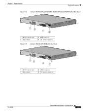
Chapter 1 Product Overview Rear Panel Description Figure 1-16 Catalyst 3560V2-24PS, 3560V2-48PS, 3560V2-24TS, 3560V2-48TS Switch Rear Panel 274670 CONSOLE 1 2 3 4 1 RJ-45 console port 2 Fan exhaust 3 RPS connector 4 AC power connector Figure 1-17 Catalyst 3560V2-24TS-SD Switch Rear Panel 274671 CONSOLE 12 3 4 1 RJ-45 console port 2 Fan exhaust 3 RPS connector 4 DC power connector OL-6337-07 Catalyst 3560 Switch Hardware Installation Guide 1-17
Chapter 1 Product Overview Rear Panel Description Figure 1-16 Catalyst 3560V2-24PS, 3560V2-48PS, 3560V2-24TS, 3560V2-48TS Switch Rear Panel 274670 CONSOLE 1 2 3 4 1 RJ-45 console port 2 Fan exhaust 3 RPS connector 4 AC power connector Figure 1-17 Catalyst 3560V2-24TS-SD Switch Rear Panel 274671 CONSOLE 12 3 4 1 RJ-45 console port 2 Fan exhaust 3 RPS connector 4 DC power connector OL-6337-07 Catalyst 3560 Switch Hardware Installation Guide 1-17
Hardware Installation Guide
Page 28
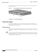
...and Catalyst 3560-12PC-S Switch Rear Panel 250607 1 2 1 Heat sinks 2 AC power connector Internal Power Supply An internal power supply powers the switch. DC Power Connector The Catalyst 3560V2-24TS-SD has an internal DC-power converter. If the supply voltage is an autoranging unit that supports input voltages between 100... and 240 VAC. Caution You must connect the Catalyst 3560V2-24TS-SD switch only to a DC-input power source that are diode-OR-ed into a single power block. It has dual feeds (A and B) that has an input supply voltage from ...
...and Catalyst 3560-12PC-S Switch Rear Panel 250607 1 2 1 Heat sinks 2 AC power connector Internal Power Supply An internal power supply powers the switch. DC Power Connector The Catalyst 3560V2-24TS-SD has an internal DC-power converter. If the supply voltage is an autoranging unit that supports input voltages between 100... and 240 VAC. Caution You must connect the Catalyst 3560V2-24TS-SD switch only to a DC-input power source that are diode-OR-ed into a single power block. It has dual feeds (A and B) that has an input supply voltage from ...

Hardware Installation Guide
Page 29
... a kit (part number ACS-DSBUASYN=) containing that supports six network devices and provides power to one or two failed switches at a time. Note When an RPS is connected to the Catalyst 3560V2-24TS-SD switch, the switch is 675 W. The Cisco RPS 675 has two output levels: -48 V and 12 V. Console Port You...
... a kit (part number ACS-DSBUASYN=) containing that supports six network devices and provides power to one or two failed switches at a time. Note When an RPS is connected to the Catalyst 3560V2-24TS-SD switch, the switch is 675 W. The Cisco RPS 675 has two output levels: -48 V and 12 V. Console Port You...
Hardware Installation Guide
Page 33
..., and connecting to the SFP modules apply to all Catalyst 3560 switches. 2 C H A P T E R Switch Installation (24- It also describes how to make connections to interpret the power-on self-test (POST) that ensures proper operation. Read the topics and perform the procedures in this order: • Preparing for Installation • Warnings, page...
..., and connecting to the SFP modules apply to all Catalyst 3560 switches. 2 C H A P T E R Switch Installation (24- It also describes how to make connections to interpret the power-on self-test (POST) that ensures proper operation. Read the topics and perform the procedures in this order: • Preparing for Installation • Warnings, page...


