
Hardware Installation Guide
Page 3
... RPS LED 1-12 Port LEDs and Modes 1-13 Dual-Purpose Port LEDs 1-15 Cable Guard 1-15 Rear Panel Description 1-15 Internal Power Supply 1-18 DC Power Connector 1-18 Cisco RPS 1-19 Cisco RPS 2300 1-19 Cisco RPS 675 1-19 Console Port 1-19 Security Slots 1-20 Management Options 1-20 Catalyst 3560 Switch Hardware Installation Guide iii
... RPS LED 1-12 Port LEDs and Modes 1-13 Dual-Purpose Port LEDs 1-15 Cable Guard 1-15 Rear Panel Description 1-15 Internal Power Supply 1-18 DC Power Connector 1-18 Cisco RPS 1-19 Cisco RPS 2300 1-19 Cisco RPS 675 1-19 Console Port 1-19 Security Slots 1-20 Management Options 1-20 Catalyst 3560 Switch Hardware Installation Guide iii

Hardware Installation Guide
Page 4
and 48-Port Switches) 2-1 Preparing for Installation 2-1 Warnings 2-2 Installation Guidelines 2-5 Box Contents 2-6 Tools and Equipment 2-6 Verifying Switch Operation 2-6 Powering Off the Switch 2-7 Installing the Switch 2-7 Rack-Mounting 2-7 Removing Screws from SFP Module Slots 2-17 Inserting and Removing the SFP Module Patch Cable 2-18 10/...
and 48-Port Switches) 2-1 Preparing for Installation 2-1 Warnings 2-2 Installation Guidelines 2-5 Box Contents 2-6 Tools and Equipment 2-6 Verifying Switch Operation 2-6 Powering Off the Switch 2-7 Installing the Switch 2-7 Rack-Mounting 2-7 Removing Screws from SFP Module Slots 2-17 Inserting and Removing the SFP Module Patch Cable 2-18 10/...
Hardware Installation Guide
Page 5
4 C H A P T E R Box Contents 3-7 Tools and Equipment 3-7 Verifying Switch Operation 3-7 Powering Off the Switch 3-7 Installing the Switch 3-7 Desk or Shelf Mounting 3-8 Desk or Shelf Mounting (Unsecured) 3-8 Desk or Shelf Mounting (Secured) 3-8 Under the Desk ... 3-16 Attaching Brackets to the Switch 3-16 Mounting the Switch in a 19-Inch Rack 3-17 Wall-Mounting (with Rack-Mount Brackets) 3-17 Securing the AC Power Cord 3-19 Where to Go Next 3-20 Troubleshooting 4-1 Diagnosing Problems 4-1 Evaluate Switch POST Results 4-2 Monitor Switch LEDs 4-2 Verify Switch Connections 4-2 Bad or Damaged Cable ...
4 C H A P T E R Box Contents 3-7 Tools and Equipment 3-7 Verifying Switch Operation 3-7 Powering Off the Switch 3-7 Installing the Switch 3-7 Desk or Shelf Mounting 3-8 Desk or Shelf Mounting (Unsecured) 3-8 Desk or Shelf Mounting (Secured) 3-8 Under the Desk ... 3-16 Attaching Brackets to the Switch 3-16 Mounting the Switch in a 19-Inch Rack 3-17 Wall-Mounting (with Rack-Mount Brackets) 3-17 Securing the AC Power Cord 3-19 Where to Go Next 3-20 Troubleshooting 4-1 Diagnosing Problems 4-1 Evaluate Switch POST Results 4-2 Monitor Switch LEDs 4-2 Verify Switch Connections 4-2 Bad or Damaged Cable ...

Hardware Installation Guide
Page 6
... Cable Pinouts B-5 Four Twisted-Pair Cable Pinouts for 1000BASE-T Ports B-6 Identifying a Crossover Cable B-6 Adapter Pinouts B-7 Connecting to DC Power C-1 Connecting to DC Power C-1 Preparing for Installation C-2 Grounding the Switch C-2 Wiring the DC-Input Power Source C-5 Configuring the Switch with the CLI-Based Setup Program D-1 Preparing for Setup D-1 Completing the Setup Program D-3 Catalyst 3560...
... Cable Pinouts B-5 Four Twisted-Pair Cable Pinouts for 1000BASE-T Ports B-6 Identifying a Crossover Cable B-6 Adapter Pinouts B-7 Connecting to DC Power C-1 Connecting to DC Power C-1 Preparing for Installation C-2 Grounding the Switch C-2 Wiring the DC-Input Power Source C-5 Configuring the Switch with the CLI-Based Setup Program D-1 Preparing for Setup D-1 Completing the Setup Program D-3 Catalyst 3560...
Hardware Installation Guide
Page 8
... also included in the Regulatory Compliance and Safety Information for Cisco Network Assistant • Cisco Small Form-Factor Pluggable Modules Installation Notes • Cisco CWDM GBIC and CWDM SFP Installation Note • Cisco RPS 2300 Redundant Power System Hardware Installation Guide • Cisco RPS 675 Redundant Power System Hardware Installation Guide These compatibility matrix documents are available...
... also included in the Regulatory Compliance and Safety Information for Cisco Network Assistant • Cisco Small Form-Factor Pluggable Modules Installation Notes • Cisco CWDM GBIC and CWDM SFP Installation Note • Cisco RPS 2300 Redundant Power System Hardware Installation Guide • Cisco RPS 675 Redundant Power System Hardware Installation Guide These compatibility matrix documents are available...

Hardware Installation Guide
Page 11
... devices like workstations, Cisco Wireless Access Points, Cisco IP Phones, and other network devices such as servers, routers, and other network devices. The getting started guide provides switch management options, basic rack-mounting procedures, port and module connections, power connection procedures, and troubleshooting... 3560 Switch Getting Started Guide for instructions on AC power and supplies backup DC power to the switches. Features The 24- See the switch software configuration guide for an optional Cisco RPS 2300 or Cisco RPS 675 that operates on how to use Express...
... devices like workstations, Cisco Wireless Access Points, Cisco IP Phones, and other network devices such as servers, routers, and other network devices. The getting started guide provides switch management options, basic rack-mounting procedures, port and module connections, power connection procedures, and troubleshooting... 3560 Switch Getting Started Guide for instructions on AC power and supplies backup DC power to the switches. Features The 24- See the switch software configuration guide for an optional Cisco RPS 2300 or Cisco RPS 675 that operates on how to use Express...

Hardware Installation Guide
Page 12
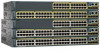
...) • 1000BASE-ZX • Coarse Wavelength-Division Multiplexing (CWDM) • SFP module patch cable. (CAB-SFP-50CM=.) Switches running Cisco IOS Release 12.2(25)SEB or later support this patch cable. and 12-port switches) • 100BASE-FX • 100BASE-LX (only...100BASE-BX10 (only Catalyst 3560 8- Features Chapter 1 Product Overview Table 1-1 Catalyst 3560 Switch Model Descriptions Switch Model Description FastEthernet Catalyst 3560-24PS 24 10/100 Power over Ethernet (PoE) ports and 2 small form-factor pluggable (SFP) module slots Catalyst 3560-24TS-S 24 10/100 ports and ...
...) • 1000BASE-ZX • Coarse Wavelength-Division Multiplexing (CWDM) • SFP module patch cable. (CAB-SFP-50CM=.) Switches running Cisco IOS Release 12.2(25)SEB or later support this patch cable. and 12-port switches) • 100BASE-FX • 100BASE-LX (only...100BASE-BX10 (only Catalyst 3560 8- Features Chapter 1 Product Overview Table 1-1 Catalyst 3560 Switch Model Descriptions Switch Model Description FastEthernet Catalyst 3560-24PS 24 10/100 Power over Ethernet (PoE) ports and 2 small form-factor pluggable (SFP) module slots Catalyst 3560-24TS-S 24 10/100 ports and ...

Hardware Installation Guide
Page 18
... port 4, and so on. You cannot configure half-duplex mode on Gigabit Ethernet interfaces if the interface speed is above the second member (port 2) on Power over Ethernet (PoE) circuits if interconnections are made aware of the pair (port 1) is set both devices support and full-duplex transmission if the attached...
... port 4, and so on. You cannot configure half-duplex mode on Gigabit Ethernet interfaces if the interface speed is above the second member (port 2) on Power over Ethernet (PoE) circuits if interconnections are made aware of the pair (port 1) is set both devices support and full-duplex transmission if the attached...

Hardware Installation Guide
Page 19
...point is enabled by default. The powered device might reboot or reestablish link with IEEE 802.3af and Cisco prestandard PoE support for Cisco IP Phones and Cisco Aironet Access Points. • Each of the Catalyst 3560-8PC, 3560-12PC-S, 3560-24PS, and 3560V2-24PS switch 10/100 ports or the ...Catalyst 3560G-24PS switch 10/100/1000 ports deliver up to a maximum power output of approximately ...
...point is enabled by default. The powered device might reboot or reestablish link with IEEE 802.3af and Cisco prestandard PoE support for Cisco IP Phones and Cisco Aironet Access Points. • Each of the Catalyst 3560-8PC, 3560-12PC-S, 3560-24PS, and 3560V2-24PS switch 10/100 ports or the ...Catalyst 3560G-24PS switch 10/100/1000 ports deliver up to a maximum power output of approximately ...

Hardware Installation Guide
Page 20
... the release notes for the active connector. 1-10 Catalyst 3560 Switch Hardware Installation Guide OL-6337-07 Front Panel Description Chapter 1 Product Overview Many legacy powered devices, including older Cisco IP phones and access points that first links up.
... the release notes for the active connector. 1-10 Catalyst 3560 Switch Hardware Installation Guide OL-6337-07 Front Panel Description Chapter 1 Product Overview Many legacy powered devices, including older Cisco IP phones and access points that first links up.

Hardware Installation Guide
Page 21
The PoE LED is not powered on the Catalyst 3560 PoE switches. 2. Figure 1-12 Catalyst 3560 Switch LEDs SYST RPS STAT ...LED 7 System LED 4 Duplex LED 8 Port LEDs 1. OL-6337-07 Catalyst 3560 Switch Hardware Installation Guide 1-11 System is receiving power but is operating normally. System is not functioning properly. All the LEDs described here are visible in the embedded device manager and Network...select one of the port modes. For information on the System LED colors during the power-on self-test (POST), see the "Verifying Switch Operation" section on page 2-6.
The PoE LED is not powered on the Catalyst 3560 PoE switches. 2. Figure 1-12 Catalyst 3560 Switch LEDs SYST RPS STAT ...LED 7 System LED 4 Duplex LED 8 Port LEDs 1. OL-6337-07 Catalyst 3560 Switch Hardware Installation Guide 1-11 System is receiving power but is operating normally. System is not functioning properly. All the LEDs described here are visible in the embedded device manager and Network...select one of the port modes. For information on the System LED colors during the power-on self-test (POST), see the "Verifying Switch Operation" section on page 2-6.
Hardware Installation Guide
Page 22
...RPS fan might have an RPS LED. For more information about the Cisco RPS 2300 and the RPS 675, see the Cisco Redundant Power System 2300 Hardware Installation Guide and the Cisco RPS 675 Redundant Power System Hardware Installation Guide. 1-12 Catalyst 3560 Switch Hardware Installation Guide... OL-6337-07 RPS is connected but is providing power to another device (redundancy has ...
...RPS fan might have an RPS LED. For more information about the Cisco RPS 2300 and the RPS 675, see the Cisco Redundant Power System 2300 Hardware Installation Guide and the Cisco RPS 675 Redundant Power System Hardware Installation Guide. 1-12 Catalyst 3560 Switch Hardware Installation Guide... OL-6337-07 RPS is connected but is providing power to another device (redundancy has ...

Hardware Installation Guide
Page 23
... you change port modes, the meanings of the 10/100 or 10/100/1000 PoE ports has been denied power, or at 10 or 100 Mb/s in different port modes. PoE PoE port power The PoE status. 1. None of the ports has a PoE fault. At least one of the 10/100 or... 10/100/1000 PoE ports have been denied power or are detected. PoE mode is the default mode. This is not...
... you change port modes, the meanings of the 10/100 or 10/100/1000 PoE ports has been denied power, or at 10 or 100 Mb/s in different port modes. PoE PoE port power The PoE status. 1. None of the ports has a PoE fault. At least one of the 10/100 or... 10/100/1000 PoE ports have been denied power or are detected. PoE mode is the default mode. This is not...

Hardware Installation Guide
Page 24
...is operating at 1000 Mb/s. Off No link, or port was administratively shut down. Alternating green-amber Link fault. PoE is denied because providing power to the switch port. PoE is on the Switch LED Color Off Meaning PoE is off due to PoE ports. Amber PoE for a link...-fault indication. Green Alternating green and amber Blinking amber If the powered device is reconfigured, the port LED can be used to connect Cisco prestandard IP Phones or wireless access points or IEEE 802.3af-compliant devices to a fault. By default, PoE ...
...is operating at 1000 Mb/s. Off No link, or port was administratively shut down. Alternating green-amber Link fault. PoE is denied because providing power to the switch port. PoE is on the Switch LED Color Off Meaning PoE is off due to PoE ports. Amber PoE for a link...-fault indication. Green Alternating green and amber Blinking amber If the powered device is reconfigured, the port LED can be used to connect Cisco prestandard IP Phones or wireless access points or IEEE 802.3af-compliant devices to a fault. By default, PoE ...
Hardware Installation Guide
Page 25
...OL-6337-07 Catalyst 3560 Switch Hardware Installation Guide 1-15 To order a cable guard (CBLGRD-C3560-12PC or CBLGRD-C3560-8PC), contact your Cisco representative. The cable guard serves a different purpose than the cable guide (see Figure 1-13) show how the port is being accidentally removed....Table 1-6. The switch console port is installed. The LED colors have an RPS connector or a fan. Rear Panel Description • Internal Power Supply, page 1-18 • Cisco RPS, page 1-19 • Console Port, page 1-19 • Security Slots, page 1-20 Note The Catalyst 3560-8PC and ...
...OL-6337-07 Catalyst 3560 Switch Hardware Installation Guide 1-15 To order a cable guard (CBLGRD-C3560-12PC or CBLGRD-C3560-8PC), contact your Cisco representative. The cable guard serves a different purpose than the cable guide (see Figure 1-13) show how the port is being accidentally removed....Table 1-6. The switch console port is installed. The LED colors have an RPS connector or a fan. Rear Panel Description • Internal Power Supply, page 1-18 • Cisco RPS, page 1-19 • Console Port, page 1-19 • Security Slots, page 1-20 Note The Catalyst 3560-8PC and ...
Hardware Installation Guide
Page 26
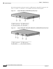
... CONSOLE 5.0A1-20R.05A-A2T,0IN500GV-6~0 HZ [email protected]@YMUO7A.TL8EA 97914 1 2 3 4 1 RJ-45 console port 3 RPS connector 2 AC power connector 4 Fan exhaust Figure 1-15 Catalyst 3560G-24PS, 3560G-48PS, 3560G-24TS, and 3560G-48TS Switch Rear Panel 119678 CONSOLE DSCPIENPCPOIUWFTIEESDRFISONURMPRPAELNYMUOATLE 12 3 4 1 RJ-45 console port 3 RPS connector 2 Fan exhaust...
... CONSOLE 5.0A1-20R.05A-A2T,0IN500GV-6~0 HZ [email protected]@YMUO7A.TL8EA 97914 1 2 3 4 1 RJ-45 console port 3 RPS connector 2 AC power connector 4 Fan exhaust Figure 1-15 Catalyst 3560G-24PS, 3560G-48PS, 3560G-24TS, and 3560G-48TS Switch Rear Panel 119678 CONSOLE DSCPIENPCPOIUWFTIEESDRFISONURMPRPAELNYMUOATLE 12 3 4 1 RJ-45 console port 3 RPS connector 2 Fan exhaust...
Hardware Installation Guide
Page 27
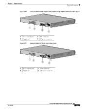
Chapter 1 Product Overview Rear Panel Description Figure 1-16 Catalyst 3560V2-24PS, 3560V2-48PS, 3560V2-24TS, 3560V2-48TS Switch Rear Panel 274670 CONSOLE 1 2 3 4 1 RJ-45 console port 2 Fan exhaust 3 RPS connector 4 AC power connector Figure 1-17 Catalyst 3560V2-24TS-SD Switch Rear Panel 274671 CONSOLE 12 3 4 1 RJ-45 console port 2 Fan exhaust 3 RPS connector 4 DC power connector OL-6337-07 Catalyst 3560 Switch Hardware Installation Guide 1-17
Chapter 1 Product Overview Rear Panel Description Figure 1-16 Catalyst 3560V2-24PS, 3560V2-48PS, 3560V2-24TS, 3560V2-48TS Switch Rear Panel 274670 CONSOLE 1 2 3 4 1 RJ-45 console port 2 Fan exhaust 3 RPS connector 4 AC power connector Figure 1-17 Catalyst 3560V2-24TS-SD Switch Rear Panel 274671 CONSOLE 12 3 4 1 RJ-45 console port 2 Fan exhaust 3 RPS connector 4 DC power connector OL-6337-07 Catalyst 3560 Switch Hardware Installation Guide 1-17
Hardware Installation Guide
Page 28
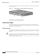
...connect the Catalyst 3560V2-24TS-SD switch only to a DC-input power source that are diode-OR-ed into a single power block. Use the supplied AC power cord to connect the AC power connector to an AC power outlet. Rear Panel Description Chapter 1 Product Overview The Catalyst 3560... 1-18 Catalyst 3560-8PC and Catalyst 3560-12PC-S Switch Rear Panel 250607 1 2 1 Heat sinks 2 AC power connector Internal Power Supply An internal power supply powers the switch. The internal power supply is not in this range, the switch might not operate properly or might be damaged. 1-18 Catalyst 3560...
...connect the Catalyst 3560V2-24TS-SD switch only to a DC-input power source that are diode-OR-ed into a single power block. Use the supplied AC power cord to connect the AC power connector to an AC power outlet. Rear Panel Description Chapter 1 Product Overview The Catalyst 3560... 1-18 Catalyst 3560-8PC and Catalyst 3560-12PC-S Switch Rear Panel 250607 1 2 1 Heat sinks 2 AC power connector Internal Power Supply An internal power supply powers the switch. The internal power supply is not in this range, the switch might not operate properly or might be damaged. 1-18 Catalyst 3560...

Hardware Installation Guide
Page 29
...supplied RJ-45-to the failed switch, preventing loss of a connected switch fails and provides power to -DB-9 female cable. For complete information about the Cisco RPS products, including compatibility matrixes listing the supported RPS for each Catalyst 3560 switch, see the... Specifications" section on the installed power-supply modules. It automatically senses when the internal power supply of these Cisco redundant power systems (RPS) to provide backup power if the switch power supply fails: • "Cisco RPS 2300" section on page 1-19 • "Cisco RPS 675" section on page ...
...supplied RJ-45-to the failed switch, preventing loss of a connected switch fails and provides power to -DB-9 female cable. For complete information about the Cisco RPS products, including compatibility matrixes listing the supported RPS for each Catalyst 3560 switch, see the... Specifications" section on the installed power-supply modules. It automatically senses when the internal power supply of these Cisco redundant power systems (RPS) to provide backup power if the switch power supply fails: • "Cisco RPS 2300" section on page 1-19 • "Cisco RPS 675" section on page ...
Hardware Installation Guide
Page 33
... 2-18 • 10/100 or 10/100/1000 Ports, page 2-19 • Connecting the Switch to Compatible Devices, page 2-20 • Where to interpret the power-on self-test (POST) that ensures proper operation. 2 C H A P T E R Switch Installation (24- and 48-port switches, including how to Go Next, page 2-24 Preparing for Installation...
... 2-18 • 10/100 or 10/100/1000 Ports, page 2-19 • Connecting the Switch to Compatible Devices, page 2-20 • Where to interpret the power-on self-test (POST) that ensures proper operation. 2 C H A P T E R Switch Installation (24- and 48-port switches, including how to Go Next, page 2-24 Preparing for Installation...


