Hardware Installation Guide
Page 2
... the United States and certain other company. (1002R) Any Internet Protocol (IP) addresses used in illustrative content is for illustrative purposes only. Catalyst 3560 Switch Hardware Installation Guide © 2004-2010 Cisco Systems, Inc. THE SPECIFICATIONS AND INFORMATION REGARDING THE PRODUCTS IN THIS MANUAL ARE SUBJECT TO CHANGE WITHOUT NOTICE. The following measures: • Turn the television or radio antenna until the interference stops...
... the United States and certain other company. (1002R) Any Internet Protocol (IP) addresses used in illustrative content is for illustrative purposes only. Catalyst 3560 Switch Hardware Installation Guide © 2004-2010 Cisco Systems, Inc. THE SPECIFICATIONS AND INFORMATION REGARDING THE PRODUCTS IN THIS MANUAL ARE SUBJECT TO CHANGE WITHOUT NOTICE. The following measures: • Turn the television or radio antenna until the interference stops...

Hardware Installation Guide
Page 11
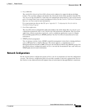
... Setting Up the Switch See the Catalyst 3560 Switch Getting Started Guide for an optional Cisco RPS 2300 or Cisco RPS 675 that operates on how to use Express Setup to initially configure your switch using the command-line interface (CLI), see Appendix D, "Configuring the Switch with the CLI-Based Setup Program." These topics are hot-swappable. This chapter provides a functional overview of how you can connect devices like workstations, Cisco Wireless Access Points, Cisco IP Phones, and other network devices such...
... Setting Up the Switch See the Catalyst 3560 Switch Getting Started Guide for an optional Cisco RPS 2300 or Cisco RPS 675 that operates on how to use Express Setup to initially configure your switch using the command-line interface (CLI), see Appendix D, "Configuring the Switch with the CLI-Based Setup Program." These topics are hot-swappable. This chapter provides a functional overview of how you can connect devices like workstations, Cisco Wireless Access Points, Cisco IP Phones, and other network devices such...

Hardware Installation Guide
Page 18
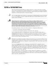
The SFP module slots are grouped in pairs. Catalyst 3560 Switch Hardware Installation Guide 1-8 OL-6337-07 You cannot configure half-duplex mode on Gigabit Ethernet interfaces if the interface speed is 1000 Mb/s. • When set for speed and duplex autonegotiation, in full duplex. • You can set both devices support and full-duplex transmission if the attached device supports it) and configures itself accordingly. Warning Voltages that both the 10/100 and...
The SFP module slots are grouped in pairs. Catalyst 3560 Switch Hardware Installation Guide 1-8 OL-6337-07 You cannot configure half-duplex mode on Gigabit Ethernet interfaces if the interface speed is 1000 Mb/s. • When set for speed and duplex autonegotiation, in full duplex. • You can set both devices support and full-duplex transmission if the attached device supports it) and configures itself accordingly. Warning Voltages that both the 10/100 and...

Hardware Installation Guide
Page 19
... connection. OL-6337-07 Catalyst 3560 Switch Hardware Installation Guide 1-9 The device manager, Network Assistant, and the CLI provide PoE settings for the powered device. In that came with the switch. Auto: When you can connect a Cisco IP Phone or Cisco Aironet Access Point to a Catalyst 3560 PoE switch 10/100 or 10/100/1000 port and to an AC power source for the cables are described in Appendix B, "Connector and Cable Specifications." • You can use the mdix auto interface configuration command to the powered device...
... connection. OL-6337-07 Catalyst 3560 Switch Hardware Installation Guide 1-9 The device manager, Network Assistant, and the CLI provide PoE settings for the powered device. In that came with the switch. Auto: When you can connect a Cisco IP Phone or Cisco Aironet Access Point to a Catalyst 3560 PoE switch 10/100 or 10/100/1000 port and to an AC power source for the cables are described in Appendix B, "Connector and Cable Specifications." • You can use the mdix auto interface configuration command to the powered device...

Hardware Installation Guide
Page 20
... your switch software. Each uplink port has two LEDs. These transceiver modules are not redundant interfaces. Front Panel Description Chapter 1 Product Overview Many legacy powered devices, including older Cisco IP phones and access points that first links up. By default, the switch dynamically selects the interface type that do not fully support IEEE 802.3af, might not support PoE when connected to establish fiber-optic and 1000BASE-T connections. SFP Module Patch Cable The switch supports the SFP module patch cable (CAB-SFP-50CM...
... your switch software. Each uplink port has two LEDs. These transceiver modules are not redundant interfaces. Front Panel Description Chapter 1 Product Overview Many legacy powered devices, including older Cisco IP phones and access points that first links up. By default, the switch dynamically selects the interface type that do not fully support IEEE 802.3af, might not support PoE when connected to establish fiber-optic and 1000BASE-T connections. SFP Module Patch Cable The switch supports the SFP module patch cable (CAB-SFP-50CM...
Hardware Installation Guide
Page 31
... console port or by using Telnet from a SNMP-compatible management station that use the switch to view switch status and performance information. See the switch software configuration guide on Cisco.com for more information. See the CiscoView documentation for more information. OL-6337-07 Catalyst 3560 Switch Hardware Installation Guide 1-21 See the Catalyst 3560 Switch Command Reference on Cisco IOS software and is running platforms such as HP OpenView or SunNet Manager. The software configuration guide also provides examples of a Simple Network Management Protocol...
... console port or by using Telnet from a SNMP-compatible management station that use the switch to view switch status and performance information. See the switch software configuration guide on Cisco.com for more information. See the CiscoView documentation for more information. OL-6337-07 Catalyst 3560 Switch Hardware Installation Guide 1-21 See the Catalyst 3560 Switch Command Reference on Cisco IOS software and is running platforms such as HP OpenView or SunNet Manager. The software configuration guide also provides examples of a Simple Network Management Protocol...
Hardware Installation Guide
Page 34
... inside the chassis; Warning To prevent the switch from the terminal block plug. If the chassis falls, it in a central office environment. Statement 171 Warning If a redundant power system (RPS) is connected to the RPS receptacle: PWR-RPS2300 / PWR675-AC-RPS-N1 Statement 370 Warning Read the wall-mounting instructions carefully before beginning installation. Statement 378 Catalyst 3560 Switch Hardware Installation Guide 2-2 OL-6337...
... inside the chassis; Warning To prevent the switch from the terminal block plug. If the chassis falls, it in a central office environment. Statement 171 Warning If a redundant power system (RPS) is connected to the RPS receptacle: PWR-RPS2300 / PWR675-AC-RPS-N1 Statement 370 Warning Read the wall-mounting instructions carefully before beginning installation. Statement 378 Catalyst 3560 Switch Hardware Installation Guide 2-2 OL-6337...

Hardware Installation Guide
Page 36
... 1024 Warning This unit might have more than one power supply connection. Statement 1046 Warning This warning symbol means danger. Preparing for preventing accidents. and 48-Port Switches) Warning This equipment must be grounded. All connections must be removed to install, replace, or service this product should be accessed only through an approved network termination unit with integral circuit protection: 10/100...
... 1024 Warning This unit might have more than one power supply connection. Statement 1046 Warning This warning symbol means danger. Preparing for preventing accidents. and 48-Port Switches) Warning This equipment must be grounded. All connections must be removed to install, replace, or service this product should be accessed only through an approved network termination unit with integral circuit protection: 10/100...

Hardware Installation Guide
Page 38
... for support. To power on the switch, connect one SFP module slot) Box Contents The switch getting started guide on Cisco.com describes the box contents. Warning Attach only the following Cisco RPS model to rack-mount the switch. International Electrotechnical Commission (IEC) IP-20 This applies to the AC power connector on a table or shelf, you install the switch in standby mode. Catalyst 3560-8PC switch-8 10/100 PoE ports and 1 dual-purpose port (one...
... for support. To power on the switch, connect one SFP module slot) Box Contents The switch getting started guide on Cisco.com describes the box contents. Warning Attach only the following Cisco RPS model to rack-mount the switch. International Electrotechnical Commission (IEC) IP-20 This applies to the AC power connector on a table or shelf, you install the switch in standby mode. Catalyst 3560-8PC switch-8 10/100 PoE ports and 1 dual-purpose port (one...
Hardware Installation Guide
Page 51
... default setting is enabled by default. Caution PoE faults are caused when noncompliant cabling or powered devices are made aware of security. You cannot configure half-duplex mode on the Catalyst 3560 PoE switches either a crossover or a straight-through the use the mdix auto interface configuration command in no linkage. You can be used to connect Cisco prestandard IP Phones or wireless access points or IEEE 802.3af-compliant devices to a PoE port. For configuration information for copper Ethernet connections and configures the interfaces...
... default setting is enabled by default. Caution PoE faults are caused when noncompliant cabling or powered devices are made aware of security. You cannot configure half-duplex mode on the Catalyst 3560 PoE switches either a crossover or a straight-through the use the mdix auto interface configuration command in no linkage. You can be used to connect Cisco prestandard IP Phones or wireless access points or IEEE 802.3af-compliant devices to a PoE port. For configuration information for copper Ethernet connections and configures the interfaces...

Hardware Installation Guide
Page 58
... power system (RPS) is connected to the switch, install an RPS connector cover on any other equipment; Preparing for the Catalyst 3560 Switch. and 12-Port Switches) Warnings These warnings are in a central office environment. Statement 43 Warning Do not stack the chassis on the back of clearance around the ventilation openings. Statement 265 Warning Attach only the following Cisco RPS model...
... power system (RPS) is connected to the switch, install an RPS connector cover on any other equipment; Preparing for the Catalyst 3560 Switch. and 12-Port Switches) Warnings These warnings are in a central office environment. Statement 43 Warning Do not stack the chassis on the back of clearance around the ventilation openings. Statement 265 Warning Attach only the following Cisco RPS model...
Hardware Installation Guide
Page 72
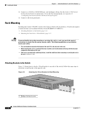
... injury when mounting or servicing this unit in the rack. Rack-Mounting Installing the Catalyst 3560-8PC switch or the Catalyst 3560 12-PC-S switch in a 19-inch rack requires a bracket kit that the system remains stable. See the Catalyst 3560 Switch Getting Started Guide for Rack-Mounting SYST STAT DPLX SPD PoE MODE CONSOLE 1x 2x 3x 4x 5x 6x 7x 8x Catalyst 3560 SERIES PoE-8 1 1 1 Phillips flat-head screws 3-16 Catalyst 3560 Switch Hardware Installation Guide OL-6337...
... injury when mounting or servicing this unit in the rack. Rack-Mounting Installing the Catalyst 3560-8PC switch or the Catalyst 3560 12-PC-S switch in a 19-inch rack requires a bracket kit that the system remains stable. See the Catalyst 3560 Switch Getting Started Guide for Rack-Mounting SYST STAT DPLX SPD PoE MODE CONSOLE 1x 2x 3x 4x 5x 6x 7x 8x Catalyst 3560 SERIES PoE-8 1 1 1 Phillips flat-head screws 3-16 Catalyst 3560 Switch Hardware Installation Guide OL-6337...
Hardware Installation Guide
Page 77
... get statistics from the CLI or from a Simple Network Management Protocol (SNMP) workstation. See the software configuration guide and the switch command reference on Cisco.com or the documentation that came with your SNMP application for more information. • Evaluate Switch POST Results, page 4-2 • Monitor Switch LEDs, page 4-2 • Verify Switch Connections, page 4-2 • Monitor Switch Performance, page 4-4 OL-6337-07 Catalyst 3560 Switch Hardware Installation Guide 4-1 They show failures in the power-on self-test (POST), port-connectivity problems...
... get statistics from the CLI or from a Simple Network Management Protocol (SNMP) workstation. See the software configuration guide and the switch command reference on Cisco.com or the documentation that came with your SNMP application for more information. • Evaluate Switch POST Results, page 4-2 • Monitor Switch LEDs, page 4-2 • Verify Switch Connections, page 4-2 • Monitor Switch Performance, page 4-4 OL-6337-07 Catalyst 3560 Switch Hardware Installation Guide 4-1 They show failures in the power-on self-test (POST), port-connectivity problems...
Hardware Installation Guide
Page 79
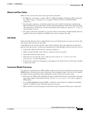
... switch. A single broken wire or one shutdown port can cause one side to show interfaces privileged EXEC command to verify the port or module error-disabled, disabled, or shutdown status. Chapter 4 Troubleshooting Diagnosing Problems Ethernet and Fiber Cables Make sure that you have encountered physical stress that causes it to function at a marginal level. A link LED does not guarantee that the module meets the requirements for loose connections. Each Cisco module...
... switch. A single broken wire or one shutdown port can cause one side to show interfaces privileged EXEC command to verify the port or module error-disabled, disabled, or shutdown status. Chapter 4 Troubleshooting Diagnosing Problems Ethernet and Fiber Cables Make sure that you have encountered physical stress that causes it to function at a marginal level. A link LED does not guarantee that the module meets the requirements for loose connections. Each Cisco module...
Hardware Installation Guide
Page 80
... unidirectional link problems. UDLD supports a normal mode of the connection. For information about enabling UDLD on both sides of operation (the default) and an aggressive mode. Catalyst 3560 Switch Hardware Installation Guide 4-4 OL-6337-07 In aggressive mode, UDLD also detects unidirectional links caused by one -way communication. If necessary, re-enable the port or the interface. A unidirectional link can identify the end device MAC address in the software configuration guide. If a port or interface is not disabled...
... unidirectional link problems. UDLD supports a normal mode of the connection. For information about enabling UDLD on both sides of operation (the default) and an aggressive mode. Catalyst 3560 Switch Hardware Installation Guide 4-4 OL-6337-07 In aggressive mode, UDLD also detects unidirectional links caused by one -way communication. If necessary, re-enable the port or the interface. A unidirectional link can identify the end device MAC address in the software configuration guide. If a port or interface is not disabled...
Hardware Installation Guide
Page 81
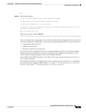
... other devices to configure the switch. 2. The switch LEDs begin blinking after an additional 8 seconds, and then the switch reboots. To maximize switch performance and to ensure a link, follow this step and run Express Setup to also be causing the problem. It is not configured, the LEDs above the Mode button turn green. Upgrade the NIC card driver to the latest version available from the switch to the factory default settings: 1. If the switch is common for cabling...
... other devices to configure the switch. 2. The switch LEDs begin blinking after an additional 8 seconds, and then the switch reboots. To maximize switch performance and to ensure a link, follow this step and run Express Setup to also be causing the problem. It is not configured, the LEDs above the Mode button turn green. Upgrade the NIC card driver to the latest version available from the switch to the factory default settings: 1. If the switch is common for cabling...

Hardware Installation Guide
Page 111
... Enter to a Cisco redundant power system (RPS), see the documentation that the switch functions properly. for any prompt. When POST completes, the system LED blinks amber. Note If you may enter a question mark '?' Default settings are usually fatal. Enter enable secret: secret_password OL-6337-07 Catalyst 3560 Switch Hardware Installation Guide D-3 If POST completes successfully, the system LED rapidly blinks green. Use ctrl-c to 28 characters; On a command switch, the host...
... Enter to a Cisco redundant power system (RPS), see the documentation that the switch functions properly. for any prompt. When POST completes, the system LED blinks amber. Note If you may enter a question mark '?' Default settings are usually fatal. Enter enable secret: secret_password OL-6337-07 Catalyst 3560 Switch Hardware Installation Guide D-3 If POST completes successfully, the system LED rapidly blinks green. Use ctrl-c to 28 characters; On a command switch, the host...
Hardware Installation Guide
Page 113
... the default configuration that you want to the small form-factor pluggable (SFP) modules, see the CMS online help. Appendix D Configuring the Switch with Cisco Network Assistant guide. For configuration information, see the Getting Started with the CLI-Based Setup Program Completing the Setup Program ! If you created. To use CMS, see Chapter 2, "Switch Installation (24- and 12-Port Switches)." To use Network Assistant, see the switch software configuration guide or the switch command reference. OL-6337-07 Catalyst 3560 Switch Hardware Installation Guide D-5
... the default configuration that you want to the small form-factor pluggable (SFP) modules, see the CMS online help. Appendix D Configuring the Switch with Cisco Network Assistant guide. For configuration information, see the Getting Started with the CLI-Based Setup Program Completing the Setup Program ! If you created. To use CMS, see Chapter 2, "Switch Installation (24- and 12-Port Switches)." To use Network Assistant, see the switch software configuration guide or the switch command reference. OL-6337-07 Catalyst 3560 Switch Hardware Installation Guide D-5

Hardware Installation Guide
Page 116
...port switches 2-15 8- Index torquing recommendation C-6 Cisco IOS command-line interface 1-21 Cisco IP Phones, connecting to 1-9, 2-20 Cisco Network Assistant 1-20 Cisco RPS See RPS CiscoView 1-21 CLI to manage switch 1-21 to set up switch D-1 code compliance warning 2-4, 3-4 command-line interface See CLI configuration examples, network 1-1 connecting to 10/100/1000 ports 2-19 to 10/100 ports 2-19 to console port B-3 to DC power C-1 to C-2 to SFP modules 2-21 to 2-23 connection procedures 2-19 to 2-23 connectors and cables 10/100 ports B-2 console port B-3 to B-8 dual-purpose ports B-3 power...
...port switches 2-15 8- Index torquing recommendation C-6 Cisco IOS command-line interface 1-21 Cisco IP Phones, connecting to 1-9, 2-20 Cisco Network Assistant 1-20 Cisco RPS See RPS CiscoView 1-21 CLI to manage switch 1-21 to set up switch D-1 code compliance warning 2-4, 3-4 command-line interface See CLI configuration examples, network 1-1 connecting to 10/100/1000 ports 2-19 to 10/100 ports 2-19 to console port B-3 to DC power C-1 to C-2 to SFP modules 2-21 to 2-23 connection procedures 2-19 to 2-23 connectors and cables 10/100 ports B-2 console port B-3 to B-8 dual-purpose ports B-3 power...

Hardware Installation Guide
Page 119
... power C-6 defined i-vii ground connection C-2 installation (24- and 12-port switches) 3-2 Catalyst 3560 Switch Hardware Installation Guide IN-5 and 12-port switches 3-16, 3-17 rear panel clearance 2-5, 3-5 description 1-15 to 1-19 removing SFP modules 2-17 to 2-18 restricted access area warning C-1 RJ-45 connector, console port B-3 RPS connecting to 2-17 shelf-mounting 24- and 48-port switches) 2-2, 3-2 security slot 1-20 serial number location 4-6 servicing equipment warning C-5 SFP module patch cable description 1-10 installing and removing 2-18 SFP modules 1000BASE-T supported...
... power C-6 defined i-vii ground connection C-2 installation (24- and 12-port switches) 3-2 Catalyst 3560 Switch Hardware Installation Guide IN-5 and 12-port switches 3-16, 3-17 rear panel clearance 2-5, 3-5 description 1-15 to 1-19 removing SFP modules 2-17 to 2-18 restricted access area warning C-1 RJ-45 connector, console port B-3 RPS connecting to 2-17 shelf-mounting 24- and 48-port switches) 2-2, 3-2 security slot 1-20 serial number location 4-6 servicing equipment warning C-5 SFP module patch cable description 1-10 installing and removing 2-18 SFP modules 1000BASE-T supported...


