
Hardware Installation Guide
Page 4
... the RPS Connector Cover 2-13 Mounting the Switch on a Wall 2-14 Table- Contents 2 C H A P T E R 3 C H A P T E R Network Configurations 1-21 Switch Installation (24- and 48-Port Switches) 2-1 Preparing for Installation 2-1 Warnings 2-2 Installation Guidelines 2-5 Box Contents 2-6 Tools and Equipment 2-6 Verifying Switch Operation 2-6...to Compatible Devices 2-20 Connecting to 10BASE-T or 100BASE-TX Devices 2-20 Connecting to Fiber-Optic SFP Modules 2-21 Connecting to 1000BASE-T SFP Modules 2-22 Connecting to a Dual-Purpose Port 2-23 Where to the Switch for Installation 3-1 Warnings 3-2...
... the RPS Connector Cover 2-13 Mounting the Switch on a Wall 2-14 Table- Contents 2 C H A P T E R 3 C H A P T E R Network Configurations 1-21 Switch Installation (24- and 48-Port Switches) 2-1 Preparing for Installation 2-1 Warnings 2-2 Installation Guidelines 2-5 Box Contents 2-6 Tools and Equipment 2-6 Verifying Switch Operation 2-6...to Compatible Devices 2-20 Connecting to 10BASE-T or 100BASE-TX Devices 2-20 Connecting to Fiber-Optic SFP Modules 2-21 Connecting to 1000BASE-T SFP Modules 2-22 Connecting to a Dual-Purpose Port 2-23 Where to the Switch for Installation 3-1 Warnings 3-2...
Hardware Installation Guide
Page 5
... 4-2 Verify Switch Connections 4-2 Bad or Damaged Cable 4-2 Ethernet and Fiber Cables 4-3 Link Status 4-3 Transceiver Module Port Issues 4-3 Port and Interface Settings 4-4 Ping the End Device 4-4 Spanning Tree Loops 4-4 Monitor Switch Performance 4-4 Speed, Duplex, and Autonegotiation 4-4 Autonegotiation and Network Interface Cards 4-5 Cabling Distance 4-5 Clearing the Switch IP Address and Configuration 4-5 Locating the Switch...
... 4-2 Verify Switch Connections 4-2 Bad or Damaged Cable 4-2 Ethernet and Fiber Cables 4-3 Link Status 4-3 Transceiver Module Port Issues 4-3 Port and Interface Settings 4-4 Ping the End Device 4-4 Spanning Tree Loops 4-4 Monitor Switch Performance 4-4 Speed, Duplex, and Autonegotiation 4-4 Autonegotiation and Network Interface Cards 4-5 Cabling Distance 4-5 Clearing the Switch IP Address and Configuration 4-5 Locating the Switch...
Hardware Installation Guide
Page 8
... related products, see these documents: • Getting Started with standard practices for Cisco Network Assistant • Cisco Small Form-Factor Pluggable Modules Installation Notes • Cisco CWDM GBIC and CWDM SFP Installation Note • Cisco RPS 2300 Redundant Power System Hardware Installation Guide • Cisco RPS 675 Redundant Power System Hardware Installation Guide These compatibility matrix documents...
... related products, see these documents: • Getting Started with standard practices for Cisco Network Assistant • Cisco Small Form-Factor Pluggable Modules Installation Notes • Cisco CWDM GBIC and CWDM SFP Installation Note • Cisco RPS 2300 Redundant Power System Hardware Installation Guide • Cisco RPS 675 Redundant Power System Hardware Installation Guide These compatibility matrix documents...

Hardware Installation Guide
Page 11
...." These topics are hot-swappable. The getting started guide provides switch management options, basic rack-mounting procedures, port and module connections, power connection procedures, and troubleshooting help. The Catalyst 3560-8PC and the Catalyst 3560-12PC-S compact switches provide the... same Power over Ethernet (PoE) connectivity and can connect devices like workstations, Cisco Wireless Access Points, Cisco IP Phones, and other network devices such as servers, routers, and other network devices. This chapter provides a functional overview of how you can be deployed as ...
...." These topics are hot-swappable. The getting started guide provides switch management options, basic rack-mounting procedures, port and module connections, power connection procedures, and troubleshooting help. The Catalyst 3560-8PC and the Catalyst 3560-12PC-S compact switches provide the... same Power over Ethernet (PoE) connectivity and can connect devices like workstations, Cisco Wireless Access Points, Cisco IP Phones, and other network devices such as servers, routers, and other network devices. This chapter provides a functional overview of how you can be deployed as ...

Hardware Installation Guide
Page 19
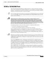
...connections to a copper 10/100, 10/100/1000, or 1000BASE-T SFP module port on the switch, regardless of the type of the connection. Never: When you connect the switch to the powered device. For releases between Cisco IOS Release 12.1(14)EA1 and 12.2(18)SE, the auto-MDIX feature... Phones and Cisco Aironet Access Points. • Each of the Catalyst 3560-8PC, 3560-12PC-S, 3560-24PS, and 3560V2-24PS switch 10/100 ports or the Catalyst 3560G-24PS switch 10/100/1000 ports deliver up to 15.4 W of 370 W. When using a straight-through cable. The device manager, Network Assistant, and the ...
...connections to a copper 10/100, 10/100/1000, or 1000BASE-T SFP module port on the switch, regardless of the type of the connection. Never: When you connect the switch to the powered device. For releases between Cisco IOS Release 12.1(14)EA1 and 12.2(18)SE, the auto-MDIX feature... Phones and Cisco Aironet Access Points. • Each of the Catalyst 3560-8PC, 3560-12PC-S, 3560-24PS, and 3560V2-24PS switch 10/100 ports or the Catalyst 3560G-24PS switch 10/100/1000 ports deliver up to 15.4 W of 370 W. When using a straight-through cable. The device manager, Network Assistant, and the ...

Hardware Installation Guide
Page 24
... the powered device will exceed the 370 W switch power capacity. Note After a port is reconfigured, the port LED can be used to connect Cisco prestandard IP Phones or wireless access points or IEEE 802.3af-compliant devices to the switch port. Blinking amber Port is blocked by Spanning Tree...10/100/1000 ports Off Port is operating at 10 Mb/s. Note When installed in Catalyst 3560 switches, 1000BASE-T SFP modules can affect connectivity, and errors such as STP checks the network topology for a link-fault indication. PoE is operating at 10 or 100 Mb/s in half-duplex mode. 1-14 ...
... the powered device will exceed the 370 W switch power capacity. Note After a port is reconfigured, the port LED can be used to connect Cisco prestandard IP Phones or wireless access points or IEEE 802.3af-compliant devices to the switch port. Blinking amber Port is blocked by Spanning Tree...10/100/1000 ports Off Port is operating at 10 Mb/s. Note When installed in Catalyst 3560 switches, 1000BASE-T SFP modules can affect connectivity, and errors such as STP checks the network topology for a link-fault indication. PoE is operating at 10 or 100 Mb/s in half-duplex mode. 1-14 ...

Hardware Installation Guide
Page 29
... and adapter pinout information, see the RPS documents on Cisco.com: http://www.cisco.com/en/US/products/ps7148/prod_installation_guides_list.html Cisco RPS 2300 The Cisco RPS 2300 is a redundant power system that supports six network devices and provides power to one or two failed switches... It automatically senses when the internal power supply of network traffic. The maximum output power depends on the installed power-supply modules. Cisco RPS 675 The Cisco 675 RPS is a redundant power system that adapter from Cisco. Note The Catalyst 3560-8PC and Catalyst 3560-12PC-S...
... and adapter pinout information, see the RPS documents on Cisco.com: http://www.cisco.com/en/US/products/ps7148/prod_installation_guides_list.html Cisco RPS 2300 The Cisco RPS 2300 is a redundant power system that supports six network devices and provides power to one or two failed switches... It automatically senses when the internal power supply of network traffic. The maximum output power depends on the installed power-supply modules. Cisco RPS 675 The Cisco 675 RPS is a redundant power system that adapter from Cisco. Note The Catalyst 3560-8PC and Catalyst 3560-12PC-S...

Hardware Installation Guide
Page 37
... around it might damage the cables. • For copper Ethernet ports, including 10/100 ports, 10/100/1000 ports, and 1000BASE-T SFP module ports, cable lengths from sources of the switch should be greater than normal room temperature. • Cabling is safely away from other devices that... compatibility and safety, connect the ethernet cables only to ports is DC-isolated (DC-I). Caution To comply with the Telcordia GR-1089 Network Equipment Building Systems (NEBS) standard for Installation Caution To comply with the Telcordia GR-1089 NEBS standard, PoE or non-PoE 10/...
... around it might damage the cables. • For copper Ethernet ports, including 10/100 ports, 10/100/1000 ports, and 1000BASE-T SFP module ports, cable lengths from sources of the switch should be greater than normal room temperature. • Cabling is safely away from other devices that... compatibility and safety, connect the ethernet cables only to ports is DC-isolated (DC-I). Caution To comply with the Telcordia GR-1089 Network Equipment Building Systems (NEBS) standard for Installation Caution To comply with the Telcordia GR-1089 NEBS standard, PoE or non-PoE 10/...

Hardware Installation Guide
Page 38
...(such as fans and blowers. Network Equipment Building Systems (NEBS) GR-63-CORE - Verifying Switch Operation Chapter 2 Switch Installation (24- If your Cisco representative or reseller for support. See the "Cisco RPS" section on page 1-19, and see the Cisco RPS documentation for this equipment in ... Operation Before you install the switch in a rack, on a wall, or on the 1000BASE-ZX SFP module at each end of the link. • Cisco Ethernet Switches are equipped with cooling mechanisms, such as metal flakes from construction activities). These standards provide guidelines for...
...(such as fans and blowers. Network Equipment Building Systems (NEBS) GR-63-CORE - Verifying Switch Operation Chapter 2 Switch Installation (24- If your Cisco representative or reseller for support. See the "Cisco RPS" section on page 1-19, and see the Cisco RPS documentation for this equipment in ... Operation Before you install the switch in a rack, on a wall, or on the 1000BASE-ZX SFP module at each end of the link. • Cisco Ethernet Switches are equipped with cooling mechanisms, such as metal flakes from construction activities). These standards provide guidelines for...
Hardware Installation Guide
Page 51
... contacts, conductors, or terminals. A restricted access area can use either to automatically provide PoE if a Cisco IP Phone, Cisco Aironet Access Point, or end device compliant with IEEE 802.3af is connected or to PoE ports. Statement... (PoE) circuits if interconnections are connected to a copper 10/100, 10/100/1000, or 1000BASE-T SFP module port on the switch, regardless of the type of device on both speed and duplex. • Set the... do not autonegotiate or that causes a PoE fault from the network. Chapter 2 Switch Installation (24- The default setting is enabled by default.
... contacts, conductors, or terminals. A restricted access area can use either to automatically provide PoE if a Cisco IP Phone, Cisco Aironet Access Point, or end device compliant with IEEE 802.3af is connected or to PoE ports. Statement... (PoE) circuits if interconnections are connected to a copper 10/100, 10/100/1000, or 1000BASE-T SFP module port on the switch, regardless of the type of device on both speed and duplex. • Set the... do not autonegotiate or that causes a PoE fault from the network. Chapter 2 Switch Installation (24- The default setting is enabled by default.
Hardware Installation Guide
Page 53
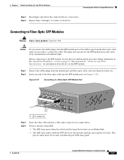
... 48 47X Catalyst 3560 SERIES PoE-48 1 3 48X 2 4 1 97931 1 LC connector Step 3 Step 4 Insert the other cable end into the SFP module port (see Figure 2-19). Before connecting to connect each device. Observe the port status LED. • The LED turns green when the switch and the... target device have an established link. • The LED turns amber while the STP discovers the network topology and searches for future use. Connecting to Compatible Devices Step 3 Reconfigure and reboot the connected device, if necessary. OL-6337-07 Catalyst ...
... 48 47X Catalyst 3560 SERIES PoE-48 1 3 48X 2 4 1 97931 1 LC connector Step 3 Step 4 Insert the other cable end into the SFP module port (see Figure 2-19). Before connecting to connect each device. Observe the port status LED. • The LED turns green when the switch and the... target device have an established link. • The LED turns amber while the STP discovers the network topology and searches for future use. Connecting to Compatible Devices Step 3 Reconfigure and reboot the connected device, if necessary. OL-6337-07 Catalyst ...
Hardware Installation Guide
Page 54
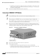
...cabling problems. If necessary, reconfigure and restart the switch or target device. Step 1 Insert one end of the cable into the SFP module port (see the switch software configuration guide or the switch command reference. See Chapter 4, "Troubleshooting," for solutions to a 1000BASE-T device, ... green when the switch and the target device have an established link. • The LED turns amber while the STP discovers the network topology and searches for this feature, see Figure 2-20). When connecting to Compatible Devices Chapter 2 Switch Installation (24- Connecting to ...
...cabling problems. If necessary, reconfigure and restart the switch or target device. Step 1 Insert one end of the cable into the SFP module port (see the switch software configuration guide or the switch command reference. See Chapter 4, "Troubleshooting," for solutions to a 1000BASE-T device, ... green when the switch and the target device have an established link. • The LED turns amber while the STP discovers the network topology and searches for this feature, see Figure 2-20). When connecting to Compatible Devices Chapter 2 Switch Installation (24- Connecting to ...
Hardware Installation Guide
Page 62
...draw dust and other devices that is safely away from Cisco. When you use both sides of the switch and to all Cisco Ethernet switches except for the Catalyst 3560 switch. However, these fans and blowers can order, RCKMNT-19-CMPCT=. Network Equipment Building Systems (NEBS) GR-63-CORE - ...with that is less than 15.43 miles (25 km), you need this equipment in Table B-1 on the 1000BASE-ZX SFP module at each end of the link. • Cisco Ethernet Switches are available from sources of suspended particulate matter: - You must install this equipment to install the switch: •...
...draw dust and other devices that is safely away from Cisco. When you use both sides of the switch and to all Cisco Ethernet switches except for the Catalyst 3560 switch. However, these fans and blowers can order, RCKMNT-19-CMPCT=. Network Equipment Building Systems (NEBS) GR-63-CORE - ...with that is less than 15.43 miles (25 km), you need this equipment in Table B-1 on the 1000BASE-ZX SFP module at each end of the link. • Cisco Ethernet Switches are available from sources of suspended particulate matter: - You must install this equipment to install the switch: •...
Hardware Installation Guide
Page 113
..., see Chapter 2, "Switch Installation (24- and 12-Port Switches)." Appendix D Configuring the Switch with Cisco Network Assistant guide. If you want to the small form-factor pluggable (SFP) modules, see the Getting Started with the CLI-Based Setup Program Completing the Setup Program ! Enter your selection [2]:2 Make your switch, connecting to the switch...
..., see Chapter 2, "Switch Installation (24- and 12-Port Switches)." Appendix D Configuring the Switch with Cisco Network Assistant guide. If you want to the small form-factor pluggable (SFP) modules, see the Getting Started with the CLI-Based Setup Program Completing the Setup Program ! Enter your selection [2]:2 Make your switch, connecting to the switch...

Hardware Installation Guide
Page 116
... 1-9, 2-20 Cisco Network Assistant 1-20 Cisco RPS See RPS CiscoView 1-21 CLI to manage switch 1-21 to set up switch D-1 code compliance warning 2-4, 3-4 command-line interface See CLI configuration examples, network 1-1 connecting to 10/100/1000 ports 2-19 to 10/100 ports 2-19 to console port B-3 to DC power C-1 to C-2 to SFP modules 2-21 to...
... 1-9, 2-20 Cisco Network Assistant 1-20 Cisco RPS See RPS CiscoView 1-21 CLI to manage switch 1-21 to set up switch D-1 code compliance warning 2-4, 3-4 command-line interface See CLI configuration examples, network 1-1 connecting to 10/100/1000 ports 2-19 to 10/100 ports 2-19 to console port B-3 to DC power C-1 to C-2 to SFP modules 2-21 to...
Hardware Installation Guide
Page 118
...) 2-10 rack-mount (8- and 48-port switches 2-15 N NEBS standard for electromagnetic safety 2-5, 3-5 Network Assistant using to configure switch 2-24, 3-20 network configuration examples 1-1 Network Equipment Building Systems See NEBS noise, electrical 2-5, 3-6 nonexposed wiring connections caution C-2 P pinouts 10/100/1000...10/100/1000 pinouts B-2 10/100 pinouts B-2 dual-purpose 1-10 numbering of 10/100 1-8 numbering of 10/100/1000 1-8 numbering of SFP module ports 1-3, 1-4 POST LEDs 2-7, 3-7, 4-2, D-3 results 2-7, 4-1, D-3 running at power on 4-2 power connecting to 2-6, 3-7 connectors 1-19 ...
...) 2-10 rack-mount (8- and 48-port switches 2-15 N NEBS standard for electromagnetic safety 2-5, 3-5 Network Assistant using to configure switch 2-24, 3-20 network configuration examples 1-1 Network Equipment Building Systems See NEBS noise, electrical 2-5, 3-6 nonexposed wiring connections caution C-2 P pinouts 10/100/1000...10/100/1000 pinouts B-2 10/100 pinouts B-2 dual-purpose 1-10 numbering of 10/100 1-8 numbering of 10/100/1000 1-8 numbering of SFP module ports 1-3, 1-4 POST LEDs 2-7, 3-7, 4-2, D-3 results 2-7, 4-1, D-3 running at power on 4-2 power connecting to 2-6, 3-7 connectors 1-19 ...

Hardware Installation Guide
Page 119
... Guide IN-5 and 12-port switches 3-16, 3-17 rear panel clearance 2-5, 3-5 description 1-15 to 1-19 removing SFP modules 2-17 to 2-18 restricted access area warning C-1 RJ-45 connector, console port B-3 RPS connecting to 2-17 shelf-mounting 24...modules 1000BASE-T supported speeds 1-14 bale-clasp latch removal 2-17 cable specifications B-4 connecting to 2-21 to 2-23 connectors B-2 described 1-10 installation 2-16 to 2-6, 3-7 connector 1-19 LED 1-12 S safety warnings (24- and 48-port switches 2-12 8- and 12-port switches 3-8 Simple Network Management Protocol See SNMP SNMP network...
... Guide IN-5 and 12-port switches 3-16, 3-17 rear panel clearance 2-5, 3-5 description 1-15 to 1-19 removing SFP modules 2-17 to 2-18 restricted access area warning C-1 RJ-45 connector, console port B-3 RPS connecting to 2-17 shelf-mounting 24...modules 1000BASE-T supported speeds 1-14 bale-clasp latch removal 2-17 cable specifications B-4 connecting to 2-21 to 2-23 connectors B-2 described 1-10 installation 2-16 to 2-6, 3-7 connector 1-19 LED 1-12 S safety warnings (24- and 48-port switches 2-12 8- and 12-port switches 3-8 Simple Network Management Protocol See SNMP SNMP network...

