Installation Guide
Page 3
... of the word partner does not imply a partnership relationship between Cisco and any other countries. and certain other company. (0304R) Catalyst 3500 Series XL Hardware Installation Guide Copyright © 2003 Cisco Systems, Inc. All rights reserved. CCIP, CCSP, the Cisco Arrow logo, the Cisco Powered Network mark, Cisco Unity, Follow Me Browsing, FormShare, and StackWise are registered...
... of the word partner does not imply a partnership relationship between Cisco and any other countries. and certain other company. (0304R) Catalyst 3500 Series XL Hardware Installation Guide Copyright © 2003 Cisco Systems, Inc. All rights reserved. CCIP, CCSP, the Cisco Arrow logo, the Cisco Powered Network mark, Cisco Unity, Follow Me Browsing, FormShare, and StackWise are registered...

Installation Guide
Page 6
... 1-31 Large Campus Configuration 1-33 Installing and Starting Up the Switch 2-1 Preparing for Using the Switch 1-25 Small- Contents 2 C H A P T E R LEDs 1-11 System LED 1-14 RPS LED 1-15 Port LEDs and Modes 1-16 Rear-Panel Description 1-21 Power Connectors 1-22 Internal Power Supply Connector 1-23 Cisco RPS Connector 1-23 Console Port 1-24 Management Options 1-24 Network...
... 1-31 Large Campus Configuration 1-33 Installing and Starting Up the Switch 2-1 Preparing for Using the Switch 1-25 Small- Contents 2 C H A P T E R LEDs 1-11 System LED 1-14 RPS LED 1-15 Port LEDs and Modes 1-16 Rear-Panel Description 1-21 Power Connectors 1-22 Internal Power Supply Connector 1-23 Cisco RPS Connector 1-23 Console Port 1-24 Management Options 1-24 Network...

Installation Guide
Page 7
... 2-13 Attaching the Optional Cable Guide 2-13 Installing the Switch on a Wall 2-15 Attaching the Brackets to the Switch 2-15 Attaching the Switch to a Wall 2-16 Installing the Switch on a Table or Shelf 2-17 Powering On the Switch and Running POST 2-17 Connecting to the 10/100 Ports... to the Console Port 2-23 Assigning Switch Information 2-24 Using the Setup Program 2-25 Using BOOTP 2-29 Default Configuration Settings 2-29 Where to Go Next 2-31 Troubleshooting 3-1 Understanding POST Results 3-2 Diagnosing Problems 3-3 Contents 78-6456-03 Catalyst 3500 Series XL Hardware Installation Guide vii
... 2-13 Attaching the Optional Cable Guide 2-13 Installing the Switch on a Wall 2-15 Attaching the Brackets to the Switch 2-15 Attaching the Switch to a Wall 2-16 Installing the Switch on a Table or Shelf 2-17 Powering On the Switch and Running POST 2-17 Connecting to the 10/100 Ports... to the Console Port 2-23 Assigning Switch Information 2-24 Using the Setup Program 2-25 Using BOOTP 2-29 Default Configuration Settings 2-29 Where to Go Next 2-31 Troubleshooting 3-1 Understanding POST Results 3-2 Diagnosing Problems 3-3 Contents 78-6456-03 Catalyst 3500 Series XL Hardware Installation Guide vii

Installation Guide
Page 8
... to a PC B-6 Connecting to a Terminal B-7 Translated Safety Warnings C-1 Attaching the Cisco RPS (model PWR600-AC-RPS) C-2 Attaching the Cisco RPS (model PWR300-AC-RPS-N1) C-4 Service Personnel Warning C-5 Qualified Personnel Warning ...C-7 Installation Instructions Warning C-9 Jewelry Removal Warning C-10 Stacking the Chassis Warning C-13 Main Disconnecting Device C-15 Overtemperature Warning C-16 TN Power Warning C-19 Ground Connection Warning C-20 Circuit Breaker (15A) Warning C-21 Catalyst...
... to a PC B-6 Connecting to a Terminal B-7 Translated Safety Warnings C-1 Attaching the Cisco RPS (model PWR600-AC-RPS) C-2 Attaching the Cisco RPS (model PWR300-AC-RPS-N1) C-4 Service Personnel Warning C-5 Qualified Personnel Warning ...C-7 Installation Instructions Warning C-9 Jewelry Removal Warning C-10 Stacking the Chassis Warning C-13 Main Disconnecting Device C-15 Overtemperature Warning C-16 TN Power Warning C-19 Ground Connection Warning C-20 Circuit Breaker (15A) Warning C-21 Catalyst...

Installation Guide
Page 9
INDEX Grounded Equipment Warning C-23 Supply Circuit Warning C-24 No On/Off Switch Warning C-25 Power Supply Warning C-27 Work During Lightning Activity Warning C-30 Product Disposal Warning C-31 Chassis Warning-Rack-Mounting and Servicing C-33 Chassis Power Connection Warning C-38 Shock Hazard from Interconnections Warning C-41 Contents 78-6456-03 Catalyst 3500 Series XL Hardware Installation Guide ix
INDEX Grounded Equipment Warning C-23 Supply Circuit Warning C-24 No On/Off Switch Warning C-25 Power Supply Warning C-27 Work During Lightning Activity Warning C-30 Product Disposal Warning C-31 Chassis Warning-Rack-Mounting and Servicing C-33 Chassis Power Connection Warning C-38 Shock Hazard from Interconnections Warning C-41 Contents 78-6456-03 Catalyst 3500 Series XL Hardware Installation Guide ix

Installation Guide
Page 25
... switches. A feature specific to the Catalyst 3524-PWR XL switch is its ability to provide inline power to Cisco IP Phones. (Phone adapters are not required when connecting to the Catalyst 3524-PWR XL 10/100 switch ports.) Figure 1-1 shows the switch models in different network topologies Features The Catalyst 3500 series XL switches-also referred to as Catalyst 3500 XL switches...
... switches. A feature specific to the Catalyst 3524-PWR XL switch is its ability to provide inline power to Cisco IP Phones. (Phone adapters are not required when connecting to the Catalyst 3524-PWR XL 10/100 switch ports.) Figure 1-1 shows the switch models in different network topologies Features The Catalyst 3500 series XL switches-also referred to as Catalyst 3500 XL switches...

Installation Guide
Page 26
...Catalyst 3500 Series XL Switches Switch Description WS-C3508G-XL 8 GBIC1-based gigabit module slots 1 SYSTEM 2 3 RPS 4 5 MODE STATUS UTIL DUPLX SPEED 6 7 8 WS-C3512-XL 12 autosensing10/100 Ethernet ports 2 GBIC-based gigabit module slots WS-C3524-XL 24 autosensing 10/100 Ethernet ports 2 fixed GBIC-based gigabit module slots WS...-C3524-PWR-XL 24 autosensing 10/100 inline-power Ethernet ports 2 GBIC-based gigabit module slots WS-C3548-XL 48 autosensing 10/100 Ethernet ports 2 GBIC-based ...
...Catalyst 3500 Series XL Switches Switch Description WS-C3508G-XL 8 GBIC1-based gigabit module slots 1 SYSTEM 2 3 RPS 4 5 MODE STATUS UTIL DUPLX SPEED 6 7 8 WS-C3512-XL 12 autosensing10/100 Ethernet ports 2 GBIC-based gigabit module slots WS-C3524-XL 24 autosensing 10/100 Ethernet ports 2 fixed GBIC-based gigabit module slots WS...-C3524-PWR-XL 24 autosensing 10/100 inline-power Ethernet ports 2 GBIC-based gigabit module slots WS-C3548-XL 48 autosensing 10/100 Ethernet ports 2 GBIC-based ...

Installation Guide
Page 27
...-based tool for managing switch clusters or an individual switch through a single IP address • Simple Network Management Protocol (SNMP) Power Redundancy • Connection for optional Cisco 600W Redundant Power System (RPS) that operates on any port • Support for command switch redundancy • Support for up to the switch 78-6456-04 Catalyst 3500 Series XL Hardware...
...-based tool for managing switch clusters or an individual switch through a single IP address • Simple Network Management Protocol (SNMP) Power Redundancy • Connection for optional Cisco 600W Redundant Power System (RPS) that operates on any port • Support for command switch redundancy • Support for up to the switch 78-6456-04 Catalyst 3500 Series XL Hardware...

Installation Guide
Page 29
... Description Table 1-2 Catalyst 3512, 3524, 3524-PWR, and 3548 XL Features (continued) Feature Description (continued) Management • Cisco IOS CLI through the console port or Telnet • CiscoView device-management application • Cluster Management Suite, a web-based tool for managing switch clusters or an individual switch through a single IP address • SNMP Power Redundancy •...
... Description Table 1-2 Catalyst 3512, 3524, 3524-PWR, and 3548 XL Features (continued) Feature Description (continued) Management • Cisco IOS CLI through the console port or Telnet • CiscoView device-management application • Cluster Management Suite, a web-based tool for managing switch clusters or an individual switch through a single IP address • SNMP Power Redundancy •...

Installation Guide
Page 31
...network device: • 10BaseT-compatible devices such as workstations, Cisco IP Phones, and hubs through standard RJ-45 connectors and Category 3, 4, or 5 cabling 78-6456-04 Catalyst 3500 Series XL Hardware Installation Guide 1-7 Chapter 1 Product Overview Figure 1-5 Catalyst 3524-PWR XL Switch Front-Panel Description 30291 12 1X 34 56 78 MODE ... 11 12 11X 12X 13 14 13X 15 16 17 18 19 20 21 22 23 24 23X 14X 24X 10/100 inline-power ports Figure 1-6 Catalyst 3548 XL Switch 1 2 GBIC module slots 28010 SYSTEM RPS 12 1X 34 56 78 9 10 11 12 13 14 15 16 15X 17 18 ...
...network device: • 10BaseT-compatible devices such as workstations, Cisco IP Phones, and hubs through standard RJ-45 connectors and Category 3, 4, or 5 cabling 78-6456-04 Catalyst 3500 Series XL Hardware Installation Guide 1-7 Chapter 1 Product Overview Figure 1-5 Catalyst 3524-PWR XL Switch Front-Panel Description 30291 12 1X 34 56 78 MODE ... 11 12 11X 12X 13 14 13X 15 16 17 18 19 20 21 22 23 24 23X 14X 24X 10/100 inline-power ports Figure 1-6 Catalyst 3548 XL Switch 1 2 GBIC module slots 28010 SYSTEM RPS 12 1X 34 56 78 9 10 11 12 13 14 15 16 15X 17 18 ...

Installation Guide
Page 32
... , twisted-pair cable. The 10/100 switch ports can be set to an AC power source. Refer to the following phones: Cisco IP Phone 7960, Cisco IP Phone 7940, and Cisco IP Phone 7910 • Automatically detect if a Cisco IP Phone is connected. The Catalyst 3548 and 3524-PWR XL switches also support per -port basis, you select...
... , twisted-pair cable. The 10/100 switch ports can be set to an AC power source. Refer to the following phones: Cisco IP Phone 7960, Cisco IP Phone 7940, and Cisco IP Phone 7910 • Automatically detect if a Cisco IP Phone is connected. The Catalyst 3548 and 3524-PWR XL switches also support per -port basis, you select...

Installation Guide
Page 33
... Front-Panel Description only provides power if a Cisco IP Phone is connected to which the Cisco IP Phone is first connected becomes its primary power source, and the second power source is its backup. For information about Cisco IP Phones, refer to nine Catalyst 3500 XL switches. You can connect the Cisco IP Phone to a Catalyst 3524-PWR XL 10...
... Front-Panel Description only provides power if a Cisco IP Phone is connected to which the Cisco IP Phone is first connected becomes its primary power source, and the second power source is its backup. For information about Cisco IP Phones, refer to nine Catalyst 3500 XL switches. You can connect the Cisco IP Phone to a Catalyst 3524-PWR XL 10...
Installation Guide
Page 35
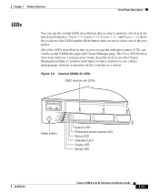
...Cisco IOS Desktop Switching Software Configuration Guide describes how to use the Cluster Management Suite to monitor individual switches and how to use the switch LEDs described in this section except the utilization meter (UTL) are visible on the VSM home page and Cluster Manager page. Figure 1-9 Catalyst...LEDs 18961 1 SYSTEM 2 3 RPS MODE STATUS UTIL DUPLX SPEED Mode button System LED Redundant power system LED Status LED Utilization LED Duplex LED Speed LED 78-6456-04 Catalyst 3500 Series XL Hardware Installation Guide 1-11 All of the port modes. Chapter 1 Product ...
...Cisco IOS Desktop Switching Software Configuration Guide describes how to use the Cluster Management Suite to monitor individual switches and how to use the switch LEDs described in this section except the utilization meter (UTL) are visible on the VSM home page and Cluster Manager page. Figure 1-9 Catalyst...LEDs 18961 1 SYSTEM 2 3 RPS MODE STATUS UTIL DUPLX SPEED Mode button System LED Redundant power system LED Status LED Utilization LED Duplex LED Speed LED 78-6456-04 Catalyst 3500 Series XL Hardware Installation Guide 1-11 All of the port modes. Chapter 1 Product ...
Installation Guide
Page 36
Front-Panel Description Figure 1-10 Catalyst 3512 and 3524 XL LEDs Port LEDs Chapter 1 Product Overview SYSTEM RPS MODE STATUS UTIL DUPLX SPEED Mode button 1 1X 23 45 67 8 9 10 11 12 11X 2X 12X System LED Redundant power system LED 22028 1-12 Catalyst 3500 Series XL Hardware Installation Guide 78-6456-04
Front-Panel Description Figure 1-10 Catalyst 3512 and 3524 XL LEDs Port LEDs Chapter 1 Product Overview SYSTEM RPS MODE STATUS UTIL DUPLX SPEED Mode button 1 1X 23 45 67 8 9 10 11 12 11X 2X 12X System LED Redundant power system LED 22028 1-12 Catalyst 3500 Series XL Hardware Installation Guide 78-6456-04

Installation Guide
Page 38
... POST, see the "Powering On the Switch and Running POST" section on . System is not functioning properly. Table 1-3 System LED Color Off Green Amber System Status System is functioning properly. System is receiving power but is operating normally. Front-Panel Description Figure 1-12 Catalyst 3548 XL LEDs Port... 9 10 11 12 13 14 15 16 15X 2X System LED 28325 16X Mode label System LED Redundant power system LED The System LED shows whether the system is receiving power and is not powered on page 2-17. 1-14 Catalyst 3500 Series XL Hardware Installation Guide 78-6456-04
... POST, see the "Powering On the Switch and Running POST" section on . System is not functioning properly. Table 1-3 System LED Color Off Green Amber System Status System is functioning properly. System is receiving power but is operating normally. Front-Panel Description Figure 1-12 Catalyst 3548 XL LEDs Port... 9 10 11 12 13 14 15 16 15X 2X System LED 28325 16X Mode label System LED Redundant power system LED The System LED shows whether the system is receiving power and is not powered on page 2-17. 1-14 Catalyst 3500 Series XL Hardware Installation Guide 78-6456-04

Installation Guide
Page 39
... when the RPS is functioning properly. Note The Cisco RPS 300 (model PWR300-AC-RPS) supports the Catalyst 3524-PWR XL switch. 78-6456-04 Catalyst 3500 Series XL Hardware Installation Guide 1-15 If the switch power supply fails, the switch powers down , or a fan on the bottom of the power supplies in the RPS could have failed. The...
... when the RPS is functioning properly. Note The Cisco RPS 300 (model PWR300-AC-RPS) supports the Catalyst 3524-PWR XL switch. 78-6456-04 Catalyst 3500 Series XL Hardware Installation Guide 1-15 If the switch power supply fails, the switch powers down , or a fan on the bottom of the power supplies in the RPS could have failed. The...

Installation Guide
Page 40
... until the desired mode is lost. When you change the port mode in use by the switch. 1-16 Catalyst 3500 Series XL Hardware Installation Guide 78-6456-04 Table 1-7 and Table 1-8 explain how to the Cisco Redundant Power System 300 Hardware Installation Guide. RPS is connected but not functioning properly. RPS is connected and...
... until the desired mode is lost. When you change the port mode in use by the switch. 1-16 Catalyst 3500 Series XL Hardware Installation Guide 78-6456-04 Table 1-7 and Table 1-8 explain how to the Cisco Redundant Power System 300 Hardware Installation Guide. RPS is connected but not functioning properly. RPS is connected and...

Installation Guide
Page 41
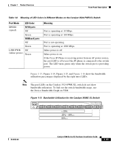
The port operating speed: 10, 100, or 1000 Mbps. Table 1-7 Meaning of its total capacity, and so on the Catalyst 3508, 3512, 3524, and 3548 XL Switches Port Mode STATUS (port status) UTL (utilization) DUPLEX LED Color Off Solid green Flashing green Alternating green-amber Solid amber ...Mode LEDs (continued) Mode LED DUPLX SPEED LINE PWR Port Mode Port duplex mode Port speed Port inline power Description The port duplex mode: full duplex or half duplex. The inline power status: on a logarithmic scale. Error frames can remain amber for possible loops. Port is operating in full...
The port operating speed: 10, 100, or 1000 Mbps. Table 1-7 Meaning of its total capacity, and so on the Catalyst 3508, 3512, 3524, and 3548 XL Switches Port Mode STATUS (port status) UTL (utilization) DUPLEX LED Color Off Solid green Flashing green Alternating green-amber Solid amber ...Mode LEDs (continued) Mode LED DUPLX SPEED LINE PWR Port Mode Port duplex mode Port speed Port inline power Description The port duplex mode: full duplex or half duplex. The inline power status: on a logarithmic scale. Error frames can remain amber for possible loops. Port is operating in full...
Installation Guide
Page 43
...Catalyst 3524-PWR XL switch do not show the bandwidth utilization percentages displayed by the right-most LEDs. To find out the switch bandwidth usage, use the Device Bandwidth Graph on VSM. Inline power is operating at 100 Mbps. Port is off even if the IP phone is operating at 10 Mbps. If the Cisco.... Port is connected to the switch port. Port is providing power. The LED turns green only when the switch port is not operating. Figure 1-13 Bandwidth Utilization for the Catalyst 3508G XL Switch 1 MODE SYSTEM RPS STATUS UTIL DUPLX SPEED 2 3 4 5 Catalyst 3500 XL 6 7 8 <...
...Catalyst 3524-PWR XL switch do not show the bandwidth utilization percentages displayed by the right-most LEDs. To find out the switch bandwidth usage, use the Device Bandwidth Graph on VSM. Inline power is operating at 100 Mbps. Port is off even if the IP phone is operating at 10 Mbps. If the Cisco.... Port is connected to the switch port. Port is providing power. The LED turns green only when the switch port is not operating. Figure 1-13 Bandwidth Utilization for the Catalyst 3508G XL Switch 1 MODE SYSTEM RPS STATUS UTIL DUPLX SPEED 2 3 4 5 Catalyst 3500 XL 6 7 8 <...

Installation Guide
Page 45
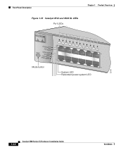
...75A 50-60HZ CONSOLE DC INPUTS SPECIFIED IFNOMRARNEUMAOL.T+E3P.3OVW***E@R1S4UAP, PLY DC INPUT +12V***@3A AC power connector RJ-45 console port Redundant power system connector Figure 1-18 Catalyst 3512 and 3524 XL Rear Panel Fans 18964 RATING 100-127/200-240V~ 1.0A/0.5A 50-60HZ.... +5V @24A, +12V @.5A RJ-45 console port Redundant power system connector Fans Catalyst 3500 Series XL Hardware Installation Guide 1-21 Chapter 1 Product Overview Rear-Panel Description Rear-Panel Description Switch rear panels have an AC power connector, an RPS connector, and an RJ-45 console port (see...
...75A 50-60HZ CONSOLE DC INPUTS SPECIFIED IFNOMRARNEUMAOL.T+E3P.3OVW***E@R1S4UAP, PLY DC INPUT +12V***@3A AC power connector RJ-45 console port Redundant power system connector Figure 1-18 Catalyst 3512 and 3524 XL Rear Panel Fans 18964 RATING 100-127/200-240V~ 1.0A/0.5A 50-60HZ.... +5V @24A, +12V @.5A RJ-45 console port Redundant power system connector Fans Catalyst 3500 Series XL Hardware Installation Guide 1-21 Chapter 1 Product Overview Rear-Panel Description Rear-Panel Description Switch rear panels have an AC power connector, an RPS connector, and an RJ-45 console port (see...
