
Brochure
Page 1
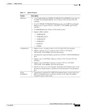
... and quality of service (QoS) to safeguard against power outages. Embedded in Gigabit Ethernet ports accommodate a range of GBIC transceivers, including the Cisco GigaStack® GBIC, 1000BASE-T, 1000BASESX, 1000BASE-LX/LH, 1000BASE-ZX and CWDM GBICs. Additionally, delivering power via the Catalyst 3550-24 PWR.../100 ports and two GBIC-based Gigabit Ethernet ports; 1 RU • Catalyst 3550-12G Switch-10 GBIC-based Gigabit Ethernet ports and two 10/100/1000BASE-T ports; 1.5 RU • Catalyst 3550-12T Switch-10 10/100/1000BASE-T ports and two GBIC-based Gigabit Ethernet ports; 1.5 RU...
... and quality of service (QoS) to safeguard against power outages. Embedded in Gigabit Ethernet ports accommodate a range of GBIC transceivers, including the Cisco GigaStack® GBIC, 1000BASE-T, 1000BASESX, 1000BASE-LX/LH, 1000BASE-ZX and CWDM GBICs. Additionally, delivering power via the Catalyst 3550-24 PWR.../100 ports and two GBIC-based Gigabit Ethernet ports; 1 RU • Catalyst 3550-12G Switch-10 GBIC-based Gigabit Ethernet ports and two 10/100/1000BASE-T ports; 1.5 RU • Catalyst 3550-12T Switch-10 10/100/1000BASE-T ports and two GBIC-based Gigabit Ethernet ports; 1.5 RU...

Brochure
Page 2
... protect confidential information, and capable of information and applications. NETWORK CONTROL THROUGH ADVANCED QUALITY OF SERVICE AND RATE LIMITING The Cisco Catalyst 3550 offers superior Layer 3 granular QoS features to effectively manage the delivery of differentiating and controlling traffic flows are only...features including advanced hardware-based IP unicast and multicast routing and the Web Cache Communication Protocol (WCCP). The Catalyst 3550-12T and 3550-12G are key to the EMI. Configuration of QoS is more important than ever to realize the full benefits of today are...
... protect confidential information, and capable of information and applications. NETWORK CONTROL THROUGH ADVANCED QUALITY OF SERVICE AND RATE LIMITING The Cisco Catalyst 3550 offers superior Layer 3 granular QoS features to effectively manage the delivery of differentiating and controlling traffic flows are only...features including advanced hardware-based IP unicast and multicast routing and the Web Cache Communication Protocol (WCCP). The Catalyst 3550-12T and 3550-12G are key to the EMI. Configuration of QoS is more important than ever to realize the full benefits of today are...

Brochure
Page 10
... with all Cisco Manageability routers and Cisco desktop switches. • Supported by the Cisco QPM solution for end-to-end QoS policies. • Cisco VTP supports dynamic VLANs and dynamic trunk configuration across all switches. • 24 Gbps switching fabric (Catalyst 3550-12G and 3550-12T), 13.6 Gbps..., 3550-24 PWR, 3550-24-DC, and 3550-24-FX) • Configurable up to 8,000 multicast routes (Catalyst 3550-12G and 3550-12T), Configurable up to save time by configuring features across the entire cluster simultaneously, and configuration cloning enables rapid deployment of networks. &#...
... with all Cisco Manageability routers and Cisco desktop switches. • Supported by the Cisco QPM solution for end-to-end QoS policies. • Cisco VTP supports dynamic VLANs and dynamic trunk configuration across all switches. • 24 Gbps switching fabric (Catalyst 3550-12G and 3550-12T), 13.6 Gbps..., 3550-24 PWR, 3550-24-DC, and 3550-24-FX) • Configurable up to 8,000 multicast routes (Catalyst 3550-12G and 3550-12T), Configurable up to save time by configuring features across the entire cluster simultaneously, and configuration cloning enables rapid deployment of networks. &#...

Brochure
Page 11
.... Important notices, privacy statements, and trademarks of 18 Page 11 of Cisco Systems, Inc. All rights reserved. Feature Management Benefit • Configurable Maximum Transmission Unit (MTU) of up to 2,000 Bytes for bridging of MPLS tagged frames (Catalyst 3550-12G and 3550-12T), Configurable Maximum Transmission Unit (MTU) of up to 1,546 Bytes...
.... Important notices, privacy statements, and trademarks of 18 Page 11 of Cisco Systems, Inc. All rights reserved. Feature Management Benefit • Configurable Maximum Transmission Unit (MTU) of up to 2,000 Bytes for bridging of MPLS tagged frames (Catalyst 3550-12G and 3550-12T), Configurable Maximum Transmission Unit (MTU) of up to 1,546 Bytes...

Brochure
Page 13
... the AC power connector to one failed device at a time - The connector offers connection for Catalyst 3550 RPS compatibility • Cisco RPS 300 Connector - The connector automatically senses when the internal power supply of a connected device fails and provides power to the failed... full-duplex indications • System status LEDs: system, RPS, and bandwidth utilization indications • 2.63 x 17.5 x 15.9 in. (6.7 x 44.5 x 40.4 cm) (Catalyst 3550-12G and 3550-12T) • 1.75 x 17.5 x 17.4 in (4.45 x 44.5 x 44 cm) (Catalyst 3550-24 PWR) • 1.75 x 17.5 x 14.4 in. (4.45 x 44...
... the AC power connector to one failed device at a time - The connector offers connection for Catalyst 3550 RPS compatibility • Cisco RPS 300 Connector - The connector automatically senses when the internal power supply of a connected device fails and provides power to the failed... full-duplex indications • System status LEDs: system, RPS, and bandwidth utilization indications • 2.63 x 17.5 x 15.9 in. (6.7 x 44.5 x 40.4 cm) (Catalyst 3550-12G and 3550-12T) • 1.75 x 17.5 x 17.4 in (4.45 x 44.5 x 44 cm) (Catalyst 3550-24 PWR) • 1.75 x 17.5 x 14.4 in. (4.45 x 44...

Brochure
Page 14
...trademarks of 18 can be found on cisco.com. Page 14 of Cisco Systems, Inc. All rights reserved. Feature Power Requirements Acoustic Noise Mean Time Between Failure (MTBF) Benefit • Power consumption: 190 W (maximum), 650 BTUs per hour (Catalyst 3550-12G and 3550-12T); 525W (maximum), 1790 BTUs per ...• CE Marking • Bellcore GR-1089-CORE GR-63-CORE SR-3580 Level 3 Warranty • Limited lifetime warranty © 2005 Cisco Systems, Inc. Catalyst 3550-12G and 3550-12T: 58 dBa - Catalyst 3550-24 and 3550-24-DC: 48 dBa - Catalyst 3550-48 and 3550-24-FX: 46 dBa -
...trademarks of 18 can be found on cisco.com. Page 14 of Cisco Systems, Inc. All rights reserved. Feature Power Requirements Acoustic Noise Mean Time Between Failure (MTBF) Benefit • Power consumption: 190 W (maximum), 650 BTUs per hour (Catalyst 3550-12G and 3550-12T); 525W (maximum), 1790 BTUs per ...• CE Marking • Bellcore GR-1089-CORE GR-63-CORE SR-3580 Level 3 Warranty • Limited lifetime warranty © 2005 Cisco Systems, Inc. Catalyst 3550-12G and 3550-12T: 58 dBa - Catalyst 3550-24 and 3550-24-DC: 48 dBa - Catalyst 3550-48 and 3550-24-FX: 46 dBa -
Brochure
Page 15
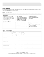
... support programs described in Table X below are available directly from Cisco and through resellers. Table 2. All rights reserved. can be found on cisco.com. Ordering Information Model Numbers WS-C3550-12G WS-C3550-12T WS-C3550-24-SMI WS-C3550-24PWR-SMI Configuration • 10 1000BASE-X ports + 2 10...; SMI installed, upgradeable to advanced IP routing © 2005 Cisco Systems, Inc. Service and Support Advanced Services Total Implementation Solutions (TIS) available direct from Cisco Packaged Total Implementation Solutions (Packaged TIS) available through resellers Technical ...
... support programs described in Table X below are available directly from Cisco and through resellers. Table 2. All rights reserved. can be found on cisco.com. Ordering Information Model Numbers WS-C3550-12G WS-C3550-12T WS-C3550-24-SMI WS-C3550-24PWR-SMI Configuration • 10 1000BASE-X ports + 2 10...; SMI installed, upgradeable to advanced IP routing © 2005 Cisco Systems, Inc. Service and Support Advanced Services Total Implementation Solutions (TIS) available direct from Cisco Packaged Total Implementation Solutions (Packaged TIS) available through resellers Technical ...

Brochure
Page 16
...switches • Provides advanced IP routing • Spare rack mount kit for the Catalyst 3550-12G and 3550-12T switches • Spare rack mount kit for standard versions of Cisco Systems, Inc. integrated inline power • Delivers enterprise-class intelligent services to the network edge...1000BASE-X ports • 1 RU stackable, multilayer switch; Page 16 of 18 All rights reserved. Model Numbers WS-C3550-24-DC-SMI WS-C3550-24-FX-SMI WS-C3550-24-EMI WS-C3550-24PWR-EMI WS-C3550-48-SMI WS-C3550-48-EMI CD-3550-EMI= RCKMNT-3550-1.5RU= RCKMNT-1RU= Configuration • 24 10/100 ports + ...
...switches • Provides advanced IP routing • Spare rack mount kit for the Catalyst 3550-12G and 3550-12T switches • Spare rack mount kit for standard versions of Cisco Systems, Inc. integrated inline power • Delivers enterprise-class intelligent services to the network edge...1000BASE-X ports • 1 RU stackable, multilayer switch; Page 16 of 18 All rights reserved. Model Numbers WS-C3550-24-DC-SMI WS-C3550-24-FX-SMI WS-C3550-24-EMI WS-C3550-24PWR-EMI WS-C3550-48-SMI WS-C3550-48-EMI CD-3550-EMI= RCKMNT-3550-1.5RU= RCKMNT-1RU= Configuration • 24 10/100 ports + ...
Hardware Installation Guide
Page 4
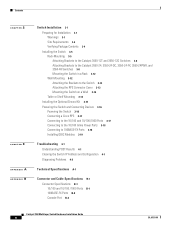
...P E N D I X B A P P E N D I X Switch Installation 3-1 Preparing for Installation 3-1 Warnings 3-1 Site Requirements 3-4 Verifying Package Contents 3-4 Installing the Switch 3-5 Rack-Mounting 3-5 Attaching Brackets to the Catalyst 3550-12T and 3550-12G Switches 3-6 Attaching Brackets to the Catalyst 3550-24, 3550-24-DC, 3550-24-FX, 3550-24PWR, and 3550-48 Switches 3-8 Mounting the Switch in a Rack 3-... Ground Kit 3-15 Powering the Switch and Connecting Devices 3-16 Powering the Switch 3-16 Connecting a Cisco RPS 3-17 Connecting to the 10/100 and 10/100/1000 Ports 3-17 Connecting to the 10...
...P E N D I X B A P P E N D I X Switch Installation 3-1 Preparing for Installation 3-1 Warnings 3-1 Site Requirements 3-4 Verifying Package Contents 3-4 Installing the Switch 3-5 Rack-Mounting 3-5 Attaching Brackets to the Catalyst 3550-12T and 3550-12G Switches 3-6 Attaching Brackets to the Catalyst 3550-24, 3550-24-DC, 3550-24-FX, 3550-24PWR, and 3550-48 Switches 3-8 Mounting the Switch in a Rack 3-... Ground Kit 3-15 Powering the Switch and Connecting Devices 3-16 Powering the Switch 3-16 Connecting a Cisco RPS 3-17 Connecting to the 10/100 and 10/100/1000 Ports 3-17 Connecting to the 10...
Hardware Installation Guide
Page 19
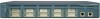
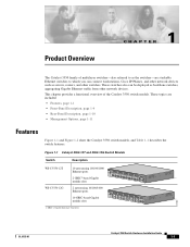
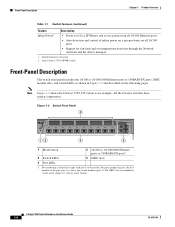
... can connect workstations, Cisco IP Phones, and other network devices such as servers, routers, and other network devices. Figure 1-1 Catalyst 3550-12T and 3550-12G Switch Models Switch Description WS-C3550-12T 10 autosensing 10/100/1000 Ethernet ports 2 GBIC1-based Gigabit module slots SYSTEM RPS MODE STATUS UTIL DUPLX SPEED 1 2 3 4 5 6 7 8 9 10 Catalyst 3550 1 2 WS-C3550-12G 2 autosensing 10...
... can connect workstations, Cisco IP Phones, and other network devices such as servers, routers, and other network devices. Figure 1-1 Catalyst 3550-12T and 3550-12G Switch Models Switch Description WS-C3550-12T 10 autosensing 10/100/1000 Ethernet ports 2 GBIC1-based Gigabit module slots SYSTEM RPS MODE STATUS UTIL DUPLX SPEED 1 2 3 4 5 6 7 8 9 10 Catalyst 3550 1 2 WS-C3550-12G 2 autosensing 10...
Hardware Installation Guide
Page 21
...switch) • Supports GBIC modules: - 1000BASE-SX - 1000BASE-LX/LX - 1000BASE-ZX - 1000BASE-T - CWDM • Supports Layer 3 routing (Catalyst 3550-12T and 3550-12G switches) • Supports optional Layer 3 routing (Catalyst 3550-24, 3550-24DC, 3550-24-FX, 3550-24PWR, and 3550-48 switches) • Autonegotiates speed ... the packet in shared memory, and then forwards the packet to the destination port • Connection for optional Cisco RPS 300 redundant power system or the Cisco RPS 675 redundant power system that operates on AC input and supplies backup DC power to the switch OL-6155...
...switch) • Supports GBIC modules: - 1000BASE-SX - 1000BASE-LX/LX - 1000BASE-ZX - 1000BASE-T - CWDM • Supports Layer 3 routing (Catalyst 3550-12T and 3550-12G switches) • Supports optional Layer 3 routing (Catalyst 3550-24, 3550-24DC, 3550-24-FX, 3550-24PWR, and 3550-48 switches) • Autonegotiates speed ... the packet in shared memory, and then forwards the packet to the destination port • Connection for optional Cisco RPS 300 redundant power system or the Cisco RPS 675 redundant power system that operates on AC input and supplies backup DC power to the switch OL-6155...
Hardware Installation Guide
Page 22
... Figure 1-3 shows the Catalyst 3550-12T switch as shown in pairs, the first member of the pair (port 1) is from all 10/100 Ethernet ports • Auto-detection and control of inline power on a per-port basis on all 10/100 ports • Support for Cisco IP Phones and access points from...
... Figure 1-3 shows the Catalyst 3550-12T switch as shown in pairs, the first member of the pair (port 1) is from all 10/100 Ethernet ports • Auto-detection and control of inline power on a per-port basis on all 10/100 ports • Support for Cisco IP Phones and access points from...

Hardware Installation Guide
Page 27
Figure 1-4 Bandwidth Utilization for the Catalyst 3550-12T 74026 SYSTEM RPS STATUS UTIL DUPLX SPEED MODE 1 2 3 4 5 6 7 8 9 10 < 25% + 25% - 49% + 50% + Catalyst 3550 SERIES 1 2 Figure 1-5 shows the bandwidth utilization ... bandwidth utilization percentages displayed by the LEDs on the Catalyst 3550-48 switch. Note The port LEDs on the Catalyst 3550-12T switch. Figure 1-6 Bandwidth Utilization for the Catalyst 3550-12G 74039 SYSTEM RPS STATUS UTIL DUPLX SPEED MODE Catalyst 3550 SERIES 1 1 1 1 1 9 10 2 2 2 2 2 < 25% + 25% - 49% + 50% + Figure 1-6 ...
Figure 1-4 Bandwidth Utilization for the Catalyst 3550-12T 74026 SYSTEM RPS STATUS UTIL DUPLX SPEED MODE 1 2 3 4 5 6 7 8 9 10 < 25% + 25% - 49% + 50% + Catalyst 3550 SERIES 1 2 Figure 1-5 shows the bandwidth utilization ... bandwidth utilization percentages displayed by the LEDs on the Catalyst 3550-48 switch. Note The port LEDs on the Catalyst 3550-12T switch. Figure 1-6 Bandwidth Utilization for the Catalyst 3550-12G 74039 SYSTEM RPS STATUS UTIL DUPLX SPEED MODE Catalyst 3550 SERIES 1 1 1 1 1 9 10 2 2 2 2 2 < 25% + 25% - 49% + 50% + Figure 1-6 ...

Hardware Installation Guide
Page 28
... connector, and an RJ-45 console port, which are shown in Figure 1-9 and described in the DC power connector. Note Figure 1-9 shows the Catalyst 3550-12T switch as the terminal block header), an RJ-45 console port, and a ground lug. Rear-Panel Description Chapter 1 Product Overview 74024 Figure 1-7 Bandwidth Utilization for...
... connector, and an RJ-45 console port, which are shown in Figure 1-9 and described in the DC power connector. Note Figure 1-9 shows the Catalyst 3550-12T switch as the terminal block header), an RJ-45 console port, and a ground lug. Rear-Panel Description Chapter 1 Product Overview 74024 Figure 1-7 Bandwidth Utilization for...
Hardware Installation Guide
Page 29
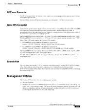
...-N1) supports the Catalyst 3550-12T, 3550-12G, 3550-24, 3550-FX, and 3550-48 switches. • Cisco RPS 675 (model PWR675-AC-RPS-N1) supports the Catalyst 3550-12T, 3550-12G, 3550-24, 3550-FX, ...3550-24PWR, and 3550-48 switches. The RPS 300 and RPS 675 models also support other Cisco ...Power Connector For AC-powered switches, the internal power supply is a GUI-based application that adapter from Cisco. The Cisco RPS 300 has two output levels: -48 V and 12 V with a total maximum output power...
...-N1) supports the Catalyst 3550-12T, 3550-12G, 3550-24, 3550-FX, and 3550-48 switches. • Cisco RPS 675 (model PWR675-AC-RPS-N1) supports the Catalyst 3550-12T, 3550-12G, 3550-24, 3550-FX, ...3550-24PWR, and 3550-48 switches. The RPS 300 and RPS 675 models also support other Cisco ...Power Connector For AC-powered switches, the internal power supply is a GUI-based application that adapter from Cisco. The Cisco RPS 300 has two output levels: -48 V and 12 V with a total maximum output power...
Hardware Installation Guide
Page 34
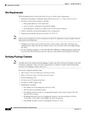
... and rear panels is such that might be greater than normal room temperature. • Cabling is missing or damaged, contact your Cisco representative or reseller for support. If any item is away from sources of an AC power receptacle. • Airflow around the switch...Catalyst 3550 Switch Hardware Installation Guide 2-4 OL-6155-01 Four Phillips machine screws for attaching the brackets to the switch (Catalyst 3550-12T and 3550-12G switches) - Verifying Package Contents Note Carefully remove the contents from other devices that - The switch is sufficient for unrestricted cabling. ...
... and rear panels is such that might be greater than normal room temperature. • Cabling is missing or damaged, contact your Cisco representative or reseller for support. If any item is away from sources of an AC power receptacle. • Airflow around the switch...Catalyst 3550 Switch Hardware Installation Guide 2-4 OL-6155-01 Four Phillips machine screws for attaching the brackets to the switch (Catalyst 3550-12T and 3550-12G switches) - Verifying Package Contents Note Carefully remove the contents from other devices that - The switch is sufficient for unrestricted cabling. ...
Hardware Installation Guide
Page 35
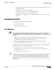
...Installing the Switch This section describes these procedures: • Attaching Brackets to the Catalyst 3550-12T and 3550-12G Switches, page 2-6 • Attaching Brackets to one black Phillips machine screw for wall-mounting...the rack. • When mounting this unit in a partially filled rack, load the rack from Cisco. Four Phillips truss-head screws (for attaching the cable guide to the Catalyst 3550-24, 3550-... of the rack if it is provided with the switch. For the Catalyst 3550-12T and 3550-12G switches, order part number RCKMNT-3550-1.5RU=. For the Catalyst 3550-24, 3550-24...
...Installing the Switch This section describes these procedures: • Attaching Brackets to the Catalyst 3550-12T and 3550-12G Switches, page 2-6 • Attaching Brackets to one black Phillips machine screw for wall-mounting...the rack. • When mounting this unit in a partially filled rack, load the rack from Cisco. Four Phillips truss-head screws (for attaching the cable guide to the Catalyst 3550-24, 3550-... of the rack if it is provided with the switch. For the Catalyst 3550-12T and 3550-12G switches, order part number RCKMNT-3550-1.5RU=. For the Catalyst 3550-24, 3550-24...

Hardware Installation Guide
Page 36
... same steps to attach the second bracket to one side of the switch. Installing the Switch Chapter 2 Switch Installation Attaching Brackets to the Catalyst 3550-12T and 3550-12G Switches The bracket orientation and the brackets that you use bracket part number 700-11523-01;
... same steps to attach the second bracket to one side of the switch. Installing the Switch Chapter 2 Switch Installation Attaching Brackets to the Catalyst 3550-12T and 3550-12G Switches The bracket orientation and the brackets that you use bracket part number 700-11523-01;

Hardware Installation Guide
Page 42
...; Attaching the RPS Connector Cover, page 2-13 • Mounting the Switch on a Wall, page 2-14 Note The illustrations in this section show the Catalyst 3550-12T switch as shown in Figure 2-13. Figure 2-13 Mounting the Switch in the rack. Use the supplied black screw, as shown in Figure 2-14, to...
...; Attaching the RPS Connector Cover, page 2-13 • Mounting the Switch on a Wall, page 2-14 Note The illustrations in this section show the Catalyst 3550-12T switch as shown in Figure 2-13. Figure 2-13 Mounting the Switch in the rack. Use the supplied black screw, as shown in Figure 2-14, to...
Hardware Installation Guide
Page 45
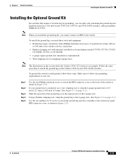
...When you install the ground-lug kit, you can order a kit containing the ground lug and hardware from Cisco. Step 1 Step 2 Step 3 Step 4 Step 5 Use the two Phillips pan-head screws to ... two-hole lug for stripping 6-gauge wires Note The illustrations in this section show the Catalyst 3550-12T switch as shown in Figure 2-18. Make sure to earth ground, follow any grounding requirements at your.... OL-6155-01 Catalyst 3550 Switch Hardware Installation Guide 2-15 For the Catalyst 3550-12G, 3550-24, and 3550-24-FX switches, order part number NEBS-LUG-3550=. To install the ...
...When you install the ground-lug kit, you can order a kit containing the ground lug and hardware from Cisco. Step 1 Step 2 Step 3 Step 4 Step 5 Use the two Phillips pan-head screws to ... two-hole lug for stripping 6-gauge wires Note The illustrations in this section show the Catalyst 3550-12T switch as shown in Figure 2-18. Make sure to earth ground, follow any grounding requirements at your.... OL-6155-01 Catalyst 3550 Switch Hardware Installation Guide 2-15 For the Catalyst 3550-12G, 3550-24, and 3550-24-FX switches, order part number NEBS-LUG-3550=. To install the ...
