
Brochure
Page 1
... power supply failures and an uninterruptable power supply (UPS) system to safeguard against power outages. The Cisco Catalyst 3550 Series Intelligent Ethernet Switches include the following configurations: • Catalyst 3550-24 Switch-24 10/100 ports and two Gigabit Interface Converter (GBIC)-based Gigabit Ethernet ports...10/100 ports and two GBIC-based Gigabit Ethernet ports; 1 RU • Catalyst 3550-12G Switch-10 GBIC-based Gigabit Ethernet ports and two 10/100/1000BASE-T ports; 1.5 RU • Catalyst 3550-12T Switch-10 10/100/1000BASE-T ports and two GBIC-based Gigabit Ethernet ports; ...
... power supply failures and an uninterruptable power supply (UPS) system to safeguard against power outages. The Cisco Catalyst 3550 Series Intelligent Ethernet Switches include the following configurations: • Catalyst 3550-24 Switch-24 10/100 ports and two Gigabit Interface Converter (GBIC)-based Gigabit Ethernet ports...10/100 ports and two GBIC-based Gigabit Ethernet ports; 1 RU • Catalyst 3550-12G Switch-10 GBIC-based Gigabit Ethernet ports and two 10/100/1000BASE-T ports; 1.5 RU • Catalyst 3550-12T Switch-10 10/100/1000BASE-T ports and two GBIC-based Gigabit Ethernet ports; ...

Brochure
Page 2
... Switches INTELLIGENCE IN THE NETWORK Networks of today are evolving to further optimizing network operations. With Cisco Catalyst Intelligent Ethernet switches, Cisco enables companies to the wiring closet, customers can be found on the network • Presence of... requirements in desktop computing power • Introduction of bandwidth-intensive applications • Expansion of highly sensitive data on cisco.com. The Catalyst 3550-12T and 3550-12G are only available with many existing mission-critical applications. All rights reserved. static and routed information protocol (RIP) ...
... Switches INTELLIGENCE IN THE NETWORK Networks of today are evolving to further optimizing network operations. With Cisco Catalyst Intelligent Ethernet switches, Cisco enables companies to the wiring closet, customers can be found on the network • Presence of... requirements in desktop computing power • Introduction of bandwidth-intensive applications • Expansion of highly sensitive data on cisco.com. The Catalyst 3550-12T and 3550-12G are only available with many existing mission-critical applications. All rights reserved. static and routed information protocol (RIP) ...

Brochure
Page 10
... • Supported by all ports (Catalyst 3550-12G, 3550-12T, and 3550- 48), 2 MB memory architecture shared by the CiscoWorks LAN Management Solution (includes Resource Manager Essentials, Campus Manager, CiscoView, and Device Fault Manager); Service Level Manager; Page 10 of Cisco Systems, Inc. ACS; and Internet...3550-24-FX) • 17.0 Mpps forwarding rate for 64-byte packets (Catalyst 3550-12G and 3550-12T), 10.1 Mpps forwarding rate for 64-byte packets (Catalyst 3550-48), 6.6 Mpps forwarding rate for Cisco routers, switches and hubs. • SNMP v1, v2c, v3 and Telnet ...
... • Supported by all ports (Catalyst 3550-12G, 3550-12T, and 3550- 48), 2 MB memory architecture shared by the CiscoWorks LAN Management Solution (includes Resource Manager Essentials, Campus Manager, CiscoView, and Device Fault Manager); Service Level Manager; Page 10 of Cisco Systems, Inc. ACS; and Internet...3550-24-FX) • 17.0 Mpps forwarding rate for 64-byte packets (Catalyst 3550-12G and 3550-12T), 10.1 Mpps forwarding rate for 64-byte packets (Catalyst 3550-48), 6.6 Mpps forwarding rate for Cisco routers, switches and hubs. • SNMP v1, v2c, v3 and Telnet ...

Brochure
Page 11
... frames (Catalyst 3550-12G and 3550-12T), Configurable Maximum Transmission Unit (MTU) of up to 1,546 Bytes for bridging of 18 Page 11 of MPLS tagged frames (Catalyst 3550-48, 3550-24, 3550-24 PWR, 3550-24-DC, and 3550-24-FX) • BRIDGE-MIB • CISCO-BULK-FILE-MIB • CISCO-CDP-MIB • CISCO-CLUSTER...
... frames (Catalyst 3550-12G and 3550-12T), Configurable Maximum Transmission Unit (MTU) of up to 1,546 Bytes for bridging of 18 Page 11 of MPLS tagged frames (Catalyst 3550-48, 3550-24, 3550-24 PWR, 3550-24-DC, and 3550-24-FX) • BRIDGE-MIB • CISCO-BULK-FILE-MIB • CISCO-CDP-MIB • CISCO-CLUSTER...

Brochure
Page 13
...of a connected device fails and provides power to the failed device, preventing loss of network traffic - See above for Catalyst 3550 RPS compatibility • Cisco RPS 300 Connector - The connector automatically senses when the internal power supply of a connected device fails and provides power to... • 2.63 x 17.5 x 15.9 in. (6.7 x 44.5 x 40.4 cm) (Catalyst 3550-12G and 3550-12T) • 1.75 x 17.5 x 17.4 in (4.45 x 44.5 x 44 cm) (Catalyst 3550-24 PWR) • 1.75 x 17.5 x 14.4 in. (4.45 x 44.5 x 36.6 cm) (Catalyst 3550-24 and 3550-24-DC) • 1.75 x 17.5 x 16.3 in. (4.45 ...
...of a connected device fails and provides power to the failed device, preventing loss of network traffic - See above for Catalyst 3550 RPS compatibility • Cisco RPS 300 Connector - The connector automatically senses when the internal power supply of a connected device fails and provides power to... • 2.63 x 17.5 x 15.9 in. (6.7 x 44.5 x 40.4 cm) (Catalyst 3550-12G and 3550-12T) • 1.75 x 17.5 x 17.4 in (4.45 x 44.5 x 44 cm) (Catalyst 3550-24 PWR) • 1.75 x 17.5 x 14.4 in. (4.45 x 44.5 x 36.6 cm) (Catalyst 3550-24 and 3550-24-DC) • 1.75 x 17.5 x 16.3 in. (4.45 ...

Brochure
Page 14
Page 14 of Cisco Systems, Inc. All rights reserved. Catalyst 3550-24 PWR: 47 dBa • 110,332 hours (Catalyst 3550-12G) • 113,658 hours (Catalyst 3550-12T) • 166,356 hours (Catalyst 3550-24 PWR) • 193,000 hours (Catalyst 3550-24) • 163,000 hours (Catalyst 3550-48) • 183,000 hours (Catalyst 3550-24-DC) • 186...
Page 14 of Cisco Systems, Inc. All rights reserved. Catalyst 3550-24 PWR: 47 dBa • 110,332 hours (Catalyst 3550-12G) • 113,658 hours (Catalyst 3550-12T) • 166,356 hours (Catalyst 3550-24 PWR) • 193,000 hours (Catalyst 3550-24) • 163,000 hours (Catalyst 3550-48) • 183,000 hours (Catalyst 3550-24-DC) • 186...

Brochure
Page 16
...-12G and 3550-12T switches • Spare rack mount kit for the Catalyst 3550-24, 3550-24 PWR, 3550-24-DC, 3550-24-FX and 3550-48 switches For More Information on cisco.com. can be found on Cisco Products, Contact: • US and Canada: 800 553-NETS (6387) • Europe...IP routing • 24 10/100 ports + 2 1000BASE-X ports • 1 RU stackable, multilayer switch; Model Numbers WS-C3550-24-DC-SMI WS-C3550-24-FX-SMI WS-C3550-24-EMI WS-C3550-24PWR-EMI WS-C3550-48-SMI WS-C3550-48-EMI CD-3550-EMI= RCKMNT-3550-1.5RU= RCKMNT-1RU= Configuration • 24 10/100 ports + 2 1000BASE-X ...
...-12G and 3550-12T switches • Spare rack mount kit for the Catalyst 3550-24, 3550-24 PWR, 3550-24-DC, 3550-24-FX and 3550-48 switches For More Information on cisco.com. can be found on Cisco Products, Contact: • US and Canada: 800 553-NETS (6387) • Europe...IP routing • 24 10/100 ports + 2 1000BASE-X ports • 1 RU stackable, multilayer switch; Model Numbers WS-C3550-24-DC-SMI WS-C3550-24-FX-SMI WS-C3550-24-EMI WS-C3550-24PWR-EMI WS-C3550-48-SMI WS-C3550-48-EMI CD-3550-EMI= RCKMNT-3550-1.5RU= RCKMNT-1RU= Configuration • 24 10/100 ports + 2 1000BASE-X ...
Hardware Installation Guide
Page 4
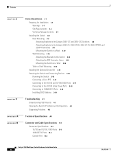
...N D I X B A P P E N D I X Switch Installation 3-1 Preparing for Installation 3-1 Warnings 3-1 Site Requirements 3-4 Verifying Package Contents 3-4 Installing the Switch 3-5 Rack-Mounting 3-5 Attaching Brackets to the Catalyst 3550-12T and 3550-12G Switches 3-6 Attaching Brackets to the Catalyst 3550-24, 3550-24-DC, 3550-24-FX, 3550-24PWR, and 3550-48 Switches 3-8 Mounting the Switch in a Rack 3-12 Wall Mounting... Kit 3-15 Powering the Switch and Connecting Devices 3-16 Powering the Switch 3-16 Connecting a Cisco RPS 3-17 Connecting to the 10/100 and 10/100/1000 Ports 3-17 Connecting to the...
...N D I X B A P P E N D I X Switch Installation 3-1 Preparing for Installation 3-1 Warnings 3-1 Site Requirements 3-4 Verifying Package Contents 3-4 Installing the Switch 3-5 Rack-Mounting 3-5 Attaching Brackets to the Catalyst 3550-12T and 3550-12G Switches 3-6 Attaching Brackets to the Catalyst 3550-24, 3550-24-DC, 3550-24-FX, 3550-24PWR, and 3550-48 Switches 3-8 Mounting the Switch in a Rack 3-12 Wall Mounting... Kit 3-15 Powering the Switch and Connecting Devices 3-16 Powering the Switch 3-16 Connecting a Cisco RPS 3-17 Connecting to the 10/100 and 10/100/1000 Ports 3-17 Connecting to the...
Hardware Installation Guide
Page 19
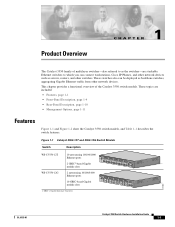
... can be deployed as servers, routers, and other network devices. Figure 1-1 Catalyst 3550-12T and 3550-12G Switch Models Switch Description WS-C3550-12T 10 autosensing 10/100/1000 Ethernet ports 2 GBIC1-based Gigabit module slots SYSTEM RPS MODE STATUS UTIL DUPLX SPEED 1 2 3 4 5 6 7 8 9 10 Catalyst 3550 1 2 WS-C3550-12G 2 autosensing 10/100/1000 Ethernet ports 10 GBIC-based Gigabit module...
... can be deployed as servers, routers, and other network devices. Figure 1-1 Catalyst 3550-12T and 3550-12G Switch Models Switch Description WS-C3550-12T 10 autosensing 10/100/1000 Ethernet ports 2 GBIC1-based Gigabit module slots SYSTEM RPS MODE STATUS UTIL DUPLX SPEED 1 2 3 4 5 6 7 8 9 10 Catalyst 3550 1 2 WS-C3550-12G 2 autosensing 10/100/1000 Ethernet ports 10 GBIC-based Gigabit module...
Hardware Installation Guide
Page 21
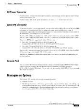
... GBIC modules: - 1000BASE-SX - 1000BASE-LX/LX - 1000BASE-ZX - 1000BASE-T - CWDM • Supports Layer 3 routing (Catalyst 3550-12T and 3550-12G switches) • Supports optional Layer 3 routing (Catalyst 3550-24, 3550-24DC, 3550-24-FX, 3550-24PWR, and 3550-48 switches) • Autonegotiates speed and duplex operation on 10...the packet in shared memory, and then forwards the packet to the destination port • Connection for optional Cisco RPS 300 redundant power system or the Cisco RPS 675 redundant power system that operates on AC input and supplies backup DC power to the switch OL-...
... GBIC modules: - 1000BASE-SX - 1000BASE-LX/LX - 1000BASE-ZX - 1000BASE-T - CWDM • Supports Layer 3 routing (Catalyst 3550-12T and 3550-12G switches) • Supports optional Layer 3 routing (Catalyst 3550-24, 3550-24DC, 3550-24-FX, 3550-24PWR, and 3550-48 switches) • Autonegotiates speed and duplex operation on 10...the packet in shared memory, and then forwards the packet to the destination port • Connection for optional Cisco RPS 300 redundant power system or the Cisco RPS 675 redundant power system that operates on AC input and supplies backup DC power to the switch OL-...
Hardware Installation Guide
Page 22
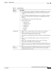
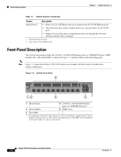
...Overview Table 1-1 Switch Features (continued) Feature Inline Power2 Description • Power for Cisco IP Phones and access points from left ) and 2 (right) or 1 (above the second member (port 2). All the Catalyst switches have similar components. For ports grouped in Figure 1-3 and described on the following...-detection and control of the pair (port 1) is above ) and 2 (below). Gigabit Interface Converter 2. Note Figure 1-3 shows the Catalyst 3550-12T switch as shown in pairs, the first member of inline power on a per-port basis on the far left. Port numbering is from...
...Overview Table 1-1 Switch Features (continued) Feature Inline Power2 Description • Power for Cisco IP Phones and access points from left ) and 2 (right) or 1 (above the second member (port 2). All the Catalyst switches have similar components. For ports grouped in Figure 1-3 and described on the following...-detection and control of the pair (port 1) is above ) and 2 (below). Gigabit Interface Converter 2. Note Figure 1-3 shows the Catalyst 3550-12T switch as shown in pairs, the first member of inline power on a per-port basis on the far left. Port numbering is from...

Hardware Installation Guide
Page 27
... the bandwidth utilization percentages displayed by the LEDs on the Catalyst 3550-12T switch. Figure 1-4 shows the bandwidth utilization percentages displayed by two. OL-6155-01 Catalyst 3550 Switch Hardware Installation Guide 1-9 Every port LED that is... 16X < 25% + 25% - 49% + 50% + Catalyst 3550 SERIES 1 2 Figure 1-7 shows the bandwidth utilization percentages displayed by the LEDs on the Catalyst 3550-48 switch. Figure 1-6 Bandwidth Utilization for the Catalyst 3550-12G 74039 SYSTEM RPS STATUS UTIL DUPLX SPEED MODE Catalyst 3550 SERIES 1 1 1 1 1 9 10 2 2 2...
... the bandwidth utilization percentages displayed by the LEDs on the Catalyst 3550-12T switch. Figure 1-4 shows the bandwidth utilization percentages displayed by two. OL-6155-01 Catalyst 3550 Switch Hardware Installation Guide 1-9 Every port LED that is... 16X < 25% + 25% - 49% + 50% + Catalyst 3550 SERIES 1 2 Figure 1-7 shows the bandwidth utilization percentages displayed by the LEDs on the Catalyst 3550-48 switch. Figure 1-6 Bandwidth Utilization for the Catalyst 3550-12G 74039 SYSTEM RPS STATUS UTIL DUPLX SPEED MODE Catalyst 3550 SERIES 1 1 1 1 1 9 10 2 2 2...

Hardware Installation Guide
Page 28
... connector, and an RJ-45 console port, which are shown in Figure 1-9 and described in the DC power connector. Note Figure 1-9 shows the Catalyst 3550-12T switch as the terminal block header), an RJ-45 console port, and a ground lug. Rear-Panel Description Chapter 1 Product Overview 74024 Figure 1-7 ...Bandwidth Utilization for the Catalyst 3550-48 SYSTEM RPS STATUS UTIL DUPLX SPEED MODE 12 1X 3 24 56 78 9 10 11 12 13 14 15...
... connector, and an RJ-45 console port, which are shown in Figure 1-9 and described in the DC power connector. Note Figure 1-9 shows the Catalyst 3550-12T switch as the terminal block header), an RJ-45 console port, and a ground lug. Rear-Panel Description Chapter 1 Product Overview 74024 Figure 1-7 ...Bandwidth Utilization for the Catalyst 3550-48 SYSTEM RPS STATUS UTIL DUPLX SPEED MODE 12 1X 3 24 56 78 9 10 11 12 13 14 15...
Hardware Installation Guide
Page 29
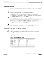
... to run on your desktop; These Cisco RPS models support the Catalyst 3550 switches: • Cisco RPS 300 (model PWR300-AC-RPS-N1) supports the Catalyst 3550-12T, 3550-12G, 3550-24, 3550-FX, and 3550-48 switches. • Cisco RPS 675 (model PWR675-AC-RPS-N1) supports the Catalyst 3550-12T, 3550-12G, 3550-24, 3550-FX, 3550-24PWR...
... to run on your desktop; These Cisco RPS models support the Catalyst 3550 switches: • Cisco RPS 300 (model PWR300-AC-RPS-N1) supports the Catalyst 3550-12T, 3550-12G, 3550-24, 3550-FX, and 3550-48 switches. • Cisco RPS 675 (model PWR675-AC-RPS-N1) supports the Catalyst 3550-12T, 3550-12G, 3550-24, 3550-FX, 3550-24PWR...
Hardware Installation Guide
Page 34
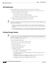
... noise, such as radios, power lines, and fluorescent lighting fixtures. If any item is sufficient for attaching the brackets to the switch (Catalyst 3550-24, 3550-24-DC, 3550-24-FX, 3550-24PWR, and 3550-48 switches) - Four rubber feet for support. Four Phillips... machine screws for attaching the brackets to the switch (Catalyst 3550-12T and 3550-12G switches) - Six Phillips flat-head screws for attaching the brackets to ports is missing or damaged, contact your Cisco representative or reseller for mounting the switch on a table - Access to a ...
... noise, such as radios, power lines, and fluorescent lighting fixtures. If any item is sufficient for attaching the brackets to the switch (Catalyst 3550-24, 3550-24-DC, 3550-24-FX, 3550-24PWR, and 3550-48 switches) - Four rubber feet for support. Four Phillips... machine screws for attaching the brackets to the switch (Catalyst 3550-12T and 3550-12G switches) - Six Phillips flat-head screws for attaching the brackets to ports is missing or damaged, contact your Cisco representative or reseller for mounting the switch on a table - Access to a ...
Hardware Installation Guide
Page 35
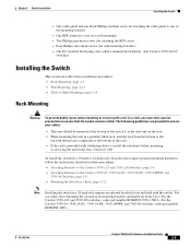
... To prevent bodily injury when mounting or servicing this unit in a partially filled rack, load the rack from Cisco. Two Phillips pan-head screws (for wall-mounting brackets) - For the Catalyst 3550-24, 3550-24-DC, 3550-24-FX, 3550-24PWR, and 3550-48 switches, order part number... heaviest component at the bottom of the rack if it is provided with the switch. For the Catalyst 3550-12T and 3550-12G switches, order part number RCKMNT-3550-1.5RU=. OL-6155-01 Catalyst 3550 Switch Hardware Installation Guide 2-5 You can order a kit containing the 24-inch rack-mounting brackets...
... To prevent bodily injury when mounting or servicing this unit in a partially filled rack, load the rack from Cisco. Two Phillips pan-head screws (for wall-mounting brackets) - For the Catalyst 3550-24, 3550-24-DC, 3550-24-FX, 3550-24PWR, and 3550-48 switches, order part number... heaviest component at the bottom of the rack if it is provided with the switch. For the Catalyst 3550-12T and 3550-12G switches, order part number RCKMNT-3550-1.5RU=. OL-6155-01 Catalyst 3550 Switch Hardware Installation Guide 2-5 You can order a kit containing the 24-inch rack-mounting brackets...

Hardware Installation Guide
Page 36
... Phillips flat-head screws SYSTEM RPS MODE STATUS UTIL DUPLX SPEED 1 3 2 4 24" Configuration 60912 Catalyst 3550 Switch Hardware Installation Guide 2-6 OL-6155-01 Installing the Switch Chapter 2 Switch Installation Attaching Brackets to the Catalyst 3550-12T and 3550-12G Switches The bracket orientation and the brackets that you use bracket part number 700-11523...
... Phillips flat-head screws SYSTEM RPS MODE STATUS UTIL DUPLX SPEED 1 3 2 4 24" Configuration 60912 Catalyst 3550 Switch Hardware Installation Guide 2-6 OL-6155-01 Installing the Switch Chapter 2 Switch Installation Attaching Brackets to the Catalyst 3550-12T and 3550-12G Switches The bracket orientation and the brackets that you use bracket part number 700-11523...

Hardware Installation Guide
Page 42
...devices installed in Figure 2-13. Figure 2-14 Attaching the Cable Guide on the Switch 74034 SYSTEM RPS MODE STATUS UTIL DUPLX SPEED 1 2 3 4 5 6 Catalyst 3550 SERIES 7 8 9 10 1 2 Cable guide screw Wall Mounting To install the switch on a wall, follow the instructions in these procedures: • ...RPS Connector Cover, page 2-13 • Mounting the Switch on a Wall, page 2-14 Note The illustrations in this section show the Catalyst 3550-12T switch as shown in Figure 2-14, to attach the cable guide to the left or right bracket. Installing the Switch Chapter 2 Switch ...
...devices installed in Figure 2-13. Figure 2-14 Attaching the Cable Guide on the Switch 74034 SYSTEM RPS MODE STATUS UTIL DUPLX SPEED 1 2 3 4 5 6 Catalyst 3550 SERIES 7 8 9 10 1 2 Cable guide screw Wall Mounting To install the switch on a wall, follow the instructions in these procedures: • ...RPS Connector Cover, page 2-13 • Mounting the Switch on a Wall, page 2-14 Note The illustrations in this section show the Catalyst 3550-12T switch as shown in Figure 2-14, to attach the cable guide to the left or right bracket. Installing the Switch Chapter 2 Switch ...
Hardware Installation Guide
Page 45
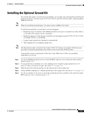
...-hole lug for stripping 6-gauge wires Note The illustrations in this section show the Catalyst 3550-12T switch as shown in Figure 2-18. If your site. For the Catalyst 3550-12G, 3550-24, and 3550-24-FX switches, order part number NEBS-LUG-3550... screws to attach the RPS connector cover to the back of the switch as an example. OL-6155-01 Catalyst 3550 Switch Hardware Installation Guide 2-15 Chapter 2 Switch Installation Installing the Optional Ground Kit Installing the Optional Ground...-stripping tool for grounding, you can order a kit containing the ground lug and hardware from Cisco.
...-hole lug for stripping 6-gauge wires Note The illustrations in this section show the Catalyst 3550-12T switch as shown in Figure 2-18. If your site. For the Catalyst 3550-12G, 3550-24, and 3550-24-FX switches, order part number NEBS-LUG-3550... screws to attach the RPS connector cover to the back of the switch as an example. OL-6155-01 Catalyst 3550 Switch Hardware Installation Guide 2-15 Chapter 2 Switch Installation Installing the Optional Ground Kit Installing the Optional Ground...-stripping tool for grounding, you can order a kit containing the ground lug and hardware from Cisco.
Hardware Installation Guide
Page 47
...(model PWR675-AC-RPS-N1) to these switch models: • Catalyst 3550-12T, 3550-12G, 3550-24, 3550-FX, or 3550-48 switch. (The Cisco RPS 300 does not support the Catalyst 3550-24-DC or 3550-24PWR switch.) Warning Attach only the Cisco RPS (model PWR300-AC-RPS-N1) to the RPS receptacle. Statement... (model PWR300-AC-RPS-N1) to these switch models. • Catalyst 3550-12T, 3550-12G, 3550-24, 3550-FX, 3550-24PWR, or 3550-48 switch. (The Cisco RPS 675 does not support the Catalyst 3550-24-DC switch.) Warning Attach only the Cisco RPS (model PWR675-AC-RPS-N1) to the RPS receptacle. Always ...
...(model PWR675-AC-RPS-N1) to these switch models: • Catalyst 3550-12T, 3550-12G, 3550-24, 3550-FX, or 3550-48 switch. (The Cisco RPS 300 does not support the Catalyst 3550-24-DC or 3550-24PWR switch.) Warning Attach only the Cisco RPS (model PWR300-AC-RPS-N1) to the RPS receptacle. Statement... (model PWR300-AC-RPS-N1) to these switch models. • Catalyst 3550-12T, 3550-12G, 3550-24, 3550-FX, 3550-24PWR, or 3550-48 switch. (The Cisco RPS 675 does not support the Catalyst 3550-24-DC switch.) Warning Attach only the Cisco RPS (model PWR675-AC-RPS-N1) to the RPS receptacle. Always ...
