
Installation Guide
Page 6
... R LEDs 1-11 System LED 1-14 RPS LED 1-15 Port LEDs and Modes 1-16 Rear-Panel Description 1-21 Power Connectors 1-22 Internal Power Supply Connector 1-23 Cisco RPS Connector 1-23 Console Port 1-24 Management Options 1-24 Network Configuration Examples 1-25 Design Concepts for Installation 2-2 Warnings 2-2 EMC Regulatory Statements 2-5 U.S.A. 2-5 Taiwan 2-5 Japan 2-6 Korea 2-6 Hungary 2-7 Installation Guidelines 2-7 Verifying Package Contents 2-8 Catalyst 3500 Series XL Hardware Installation Guide vi 78-6456-03 to Medium-Sized Network Configuration 1-29 Collapsed Backbone and Switch Cluster...
... R LEDs 1-11 System LED 1-14 RPS LED 1-15 Port LEDs and Modes 1-16 Rear-Panel Description 1-21 Power Connectors 1-22 Internal Power Supply Connector 1-23 Cisco RPS Connector 1-23 Console Port 1-24 Management Options 1-24 Network Configuration Examples 1-25 Design Concepts for Installation 2-2 Warnings 2-2 EMC Regulatory Statements 2-5 U.S.A. 2-5 Taiwan 2-5 Japan 2-6 Korea 2-6 Hungary 2-7 Installation Guidelines 2-7 Verifying Package Contents 2-8 Catalyst 3500 Series XL Hardware Installation Guide vi 78-6456-03 to Medium-Sized Network Configuration 1-29 Collapsed Backbone and Switch Cluster...

Installation Guide
Page 12
..., such as passwords or tabs, are installing the switch. Chapter 3, "Troubleshooting," describes how to identify and resolve some of the switch. Appendix C, "Translated Safety Warnings," contains translations in various languages of how the switch could be used to connect to set up the switch initial configuration. Catalyst 3500 Series XL Hardware Installation Guide xii 78-6456-04 It describes the switch ports, the standards they support, and the switch LEDs. Examples of the...
..., such as passwords or tabs, are installing the switch. Chapter 3, "Troubleshooting," describes how to identify and resolve some of the switch. Appendix C, "Translated Safety Warnings," contains translations in various languages of how the switch could be used to connect to set up the switch initial configuration. Catalyst 3500 Series XL Hardware Installation Guide xii 78-6456-04 It describes the switch ports, the standards they support, and the switch LEDs. Examples of the...
Installation Guide
Page 18
...: • Quick Start: Catalyst 3500 Series XL Cabling and Setup • Cisco IOS Desktop Switching Software Configuration Guide • Cisco IOS Desktop Switching Command Reference (online only) • Cisco Cluster Management Suite online help also provides detailed information about the fields on each window. • Release Notes for the Catalyst 2900 Series XL and Catalyst 3500 Series XL Cisco IOS Release 12.0(5)XU • Catalyst GigaStack Gigabit Interface Converter Hardware Installation Guide • Release Notes for using a Web browser to change configuration settings and to...
...: • Quick Start: Catalyst 3500 Series XL Cabling and Setup • Cisco IOS Desktop Switching Software Configuration Guide • Cisco IOS Desktop Switching Command Reference (online only) • Cisco Cluster Management Suite online help also provides detailed information about the fields on each window. • Release Notes for the Catalyst 2900 Series XL and Catalyst 3500 Series XL Cisco IOS Release 12.0(5)XU • Catalyst GigaStack Gigabit Interface Converter Hardware Installation Guide • Release Notes for using a Web browser to change configuration settings and to...

Installation Guide
Page 26
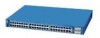
...2 48X 30210 Catalyst 3500 Series XL Hardware Installation Guide 1-2 78-6456-04 Features Chapter 1 Product Overview Figure 1-1 Catalyst 3500 Series XL Switches Switch Description WS-C3508G-XL 8 GBIC1-based gigabit module slots 1 SYSTEM 2 3 RPS 4 5 MODE STATUS UTIL DUPLX SPEED 6 7 8 WS-C3512-XL 12 autosensing10/100 Ethernet ports 2 GBIC-based gigabit module slots WS-C3524-XL 24 autosensing 10/100 Ethernet ports 2 fixed GBIC-based gigabit module slots WS-C3524-PWR-XL 24 autosensing 10/100 inline-power Ethernet ports 2 GBIC-based gigabit module slots WS-C3548-XL 48...
...2 48X 30210 Catalyst 3500 Series XL Hardware Installation Guide 1-2 78-6456-04 Features Chapter 1 Product Overview Figure 1-1 Catalyst 3500 Series XL Switches Switch Description WS-C3508G-XL 8 GBIC1-based gigabit module slots 1 SYSTEM 2 3 RPS 4 5 MODE STATUS UTIL DUPLX SPEED 6 7 8 WS-C3512-XL 12 autosensing10/100 Ethernet ports 2 GBIC-based gigabit module slots WS-C3524-XL 24 autosensing 10/100 Ethernet ports 2 fixed GBIC-based gigabit module slots WS-C3524-PWR-XL 24 autosensing 10/100 inline-power Ethernet ports 2 GBIC-based gigabit module slots WS-C3548-XL 48...

Installation Guide
Page 27
... Table 1-1 Catalyst 3508G XL Features Feature Description Performance and • 8 GBIC-based 1000BaseX Gigabit Ethernet slots Configuration • Support for up to four 1000BaseZX GBICs with the Catalyst 3508G XL switch) Management • Cisco IOS command-line interface (CLI) through the console port or Telnet • CiscoView device-management application • Cluster Management Suite, a web-based tool for managing switch clusters or an individual switch through a single IP address • Simple Network Management Protocol (SNMP) Power Redundancy • Connection...
... Table 1-1 Catalyst 3508G XL Features Feature Description Performance and • 8 GBIC-based 1000BaseX Gigabit Ethernet slots Configuration • Support for up to four 1000BaseZX GBICs with the Catalyst 3508G XL switch) Management • Cisco IOS command-line interface (CLI) through the console port or Telnet • CiscoView device-management application • Cluster Management Suite, a web-based tool for managing switch clusters or an individual switch through a single IP address • Simple Network Management Protocol (SNMP) Power Redundancy • Connection...

Installation Guide
Page 28
... voice VLAN ID (VVID) • High-speed EtherChannel connections between switches and servers • 8192 MAC addresses • IEEE 802.1p capable • CGMP to limit the flooding of IP multicast traffic • Broadcast storm control to prevent performance degradation from broadcast storms • SPAN port monitoring on any port • Support for command switch redundancy • Support for Cisco GBIC modules - GigaStack GBIC - 1000BaseSX GBIC module - 1000BaseLX/LH GBIC module - 1000BaseZX GBIC module Catalyst 3500 Series XL Hardware Installation Guide...
... voice VLAN ID (VVID) • High-speed EtherChannel connections between switches and servers • 8192 MAC addresses • IEEE 802.1p capable • CGMP to limit the flooding of IP multicast traffic • Broadcast storm control to prevent performance degradation from broadcast storms • SPAN port monitoring on any port • Support for command switch redundancy • Support for Cisco GBIC modules - GigaStack GBIC - 1000BaseSX GBIC module - 1000BaseLX/LH GBIC module - 1000BaseZX GBIC module Catalyst 3500 Series XL Hardware Installation Guide...

Installation Guide
Page 29
... provide inline power for Cisco IP Phones from all 24 10/100 Ethernet ports • Auto-detection and control of the Catalyst 3512, 3524, 3524-PWR and 3548 XL switches (Figure 1-3, Figure 1-4, Figure 1-5, and Figure 1-6) have a set of LEDs and a Mode button. (The Catalyst 3548 XL switch has a Mode label that operates on AC input and supplies DC output to the Catalyst 3512, 3524, and 3548 XL switches • Connection for managing switch clusters...
... provide inline power for Cisco IP Phones from all 24 10/100 Ethernet ports • Auto-detection and control of the Catalyst 3512, 3524, 3524-PWR and 3548 XL switches (Figure 1-3, Figure 1-4, Figure 1-5, and Figure 1-6) have a set of LEDs and a Mode button. (The Catalyst 3548 XL switch has a Mode label that operates on AC input and supplies DC output to the Catalyst 3512, 3524, and 3548 XL switches • Connection for managing switch clusters...

Installation Guide
Page 32
... work for speed and duplex autonegotiation, compliant with IEEE 802.3u. When you can use a crossover cable. When connecting the switch to workstations, servers, routers, and Cisco IP Phones, be connected to the Cisco IOS Desktop Switching Software Configuration Guide for each 10/100 port: Auto and Never. The 10/100 switch ports can be set for ports operating at 10 Mbps can control whether or not a Catalyst 3524-PWR XL 10/100 port automatically provides power...
... work for speed and duplex autonegotiation, compliant with IEEE 802.3u. When you can use a crossover cable. When connecting the switch to workstations, servers, routers, and Cisco IP Phones, be connected to the Cisco IOS Desktop Switching Software Configuration Guide for each 10/100 port: Auto and Never. The 10/100 switch ports can be set for ports operating at 10 Mbps can control whether or not a Catalyst 3524-PWR XL 10/100 port automatically provides power...

Installation Guide
Page 33
... fails, the second power source becomes the primary power source to the documentation that came with the switch. GBIC Module Slots The Cisco Gigabit Interface Converter (GBIC) module slots support the following modules to provide flexibility in the Catalyst 3508G XL switch. The GigaStack GBIC supports one full-duplex link (in a point-to-point configuration) or up to eight GBICs in media and distance options: • 1000BaseSX GBIC module for fiber connections...
... fails, the second power source becomes the primary power source to the documentation that came with the switch. GBIC Module Slots The Cisco Gigabit Interface Converter (GBIC) module slots support the following modules to provide flexibility in the Catalyst 3508G XL switch. The GigaStack GBIC supports one full-duplex link (in a point-to-point configuration) or up to eight GBICs in media and distance options: • 1000BaseSX GBIC module for fiber connections...

Installation Guide
Page 40
... you change the port mode. Table 1-7 and Table 1-8 explain how to the Cisco Redundant Power System 300 Hardware Installation Guide. The switch is down , or a fan on the RPS. To select or change the port mode in use by the switch. 1-16 Catalyst 3500 Series XL Hardware Installation Guide 78-6456-04 This is connected and operational. One of information displayed through the port LEDs. The port modes (Table 1-6) determine the type of the power supplies in the stack. RPS is the default mode. For...
... you change the port mode. Table 1-7 and Table 1-8 explain how to the Cisco Redundant Power System 300 Hardware Installation Guide. The switch is down , or a fan on the RPS. To select or change the port mode in use by the switch. 1-16 Catalyst 3500 Series XL Hardware Installation Guide 78-6456-04 This is connected and operational. One of information displayed through the port LEDs. The port modes (Table 1-6) determine the type of the power supplies in the stack. RPS is the default mode. For...

Installation Guide
Page 41
... port LED can affect connectivity, and errors such as STP checks the switch for a link-fault indication. Chapter 1 Product Overview Front-Panel Description Table 1-6 Port Mode LEDs (continued) Mode LED DUPLX SPEED LINE PWR Port Mode Port duplex mode Port speed Port inline power Description The port duplex mode: full duplex or half duplex. Port is not forwarding. The inline power status: on the Catalyst 3508, 3512, 3524, and 3548 XL Switches Port Mode STATUS (port status) UTL (utilization) DUPLEX LED Color Off Solid green Flashing green Alternating green-amber Solid amber Green...
... port LED can affect connectivity, and errors such as STP checks the switch for a link-fault indication. Chapter 1 Product Overview Front-Panel Description Table 1-6 Port Mode LEDs (continued) Mode LED DUPLX SPEED LINE PWR Port Mode Port duplex mode Port speed Port inline power Description The port duplex mode: full duplex or half duplex. Port is not forwarding. The inline power status: on the Catalyst 3508, 3512, 3524, and 3548 XL Switches Port Mode STATUS (port status) UTL (utilization) DUPLEX LED Color Off Solid green Flashing green Alternating green-amber Solid amber Green...
Installation Guide
Page 49
... Catalyst 3500 Series XL Hardware Installation Guide 1-25 If the switch is running platforms such as HP OpenView or SunNet Manager. The switch supports a comprehensive set configuration parameters and to view switch status and performance information. Chapter 1 Product Overview Network Configuration Examples • Cisco IOS command-line interface (CLI) Connect a PC or terminal directly to the console port, located on the rear panel of MIB extensions and MIB II, the IEEE 802.1D bridge MIB, and four Remote Monitoring...
... Catalyst 3500 Series XL Hardware Installation Guide 1-25 If the switch is running platforms such as HP OpenView or SunNet Manager. The switch supports a comprehensive set configuration parameters and to view switch status and performance information. Chapter 1 Product Overview Network Configuration Examples • Cisco IOS command-line interface (CLI) Connect a PC or terminal directly to the console port, located on the rear panel of MIB extensions and MIB II, the IEEE 802.1D bridge MIB, and four Remote Monitoring...

Installation Guide
Page 50
... to help control both delay and jitter within the network. Figure 1-21 illustrates three configuration examples for using Fast Ethernet or gigabit links or Fast EtherChannel or Gigabit EtherChannel links. Network Configuration Examples Chapter 1 Product Overview Table 1-9 Considerations for Increasing Network Performance Network Demands Suggested Design Methods • Too many users to the wiring closet is to connect up to other devices and create backup paths by using the Catalyst 3500 XL switches to create the following...
... to help control both delay and jitter within the network. Figure 1-21 illustrates three configuration examples for using Fast Ethernet or gigabit links or Fast EtherChannel or Gigabit EtherChannel links. Network Configuration Examples Chapter 1 Product Overview Table 1-9 Considerations for Increasing Network Performance Network Demands Suggested Design Methods • Too many users to the wiring closet is to connect up to other devices and create backup paths by using the Catalyst 3500 XL switches to create the following...

Installation Guide
Page 55
... Catalyst 3500 and 2900 XL switches. You can receive redundant power when it also is connected. You also configure each port for monitoring and controlling the network. This network also includes voice and data subnetworks, where Cisco IP Phones are created by clustering the Catalyst switches except the Catalyst 4908G-L3 switch. Chapter 1 Product Overview Network Configuration Examples Collapsed Backbone and Switch Cluster Configuration Figure 1-23 illustrates a configuration for a network of inter-VLAN routing and allows the router...
... Catalyst 3500 and 2900 XL switches. You can receive redundant power when it also is connected. You also configure each port for monitoring and controlling the network. This network also includes voice and data subnetworks, where Cisco IP Phones are created by clustering the Catalyst switches except the Catalyst 4908G-L3 switch. Chapter 1 Product Overview Network Configuration Examples Collapsed Backbone and Switch Cluster Configuration Figure 1-23 illustrates a configuration for a network of inter-VLAN routing and allows the router...
Installation Guide
Page 59
... install and start up your Catalyst 3500 XL switches and to interpret the power-on procedures • Connection procedures • Set up procedures for initial configuration • Default configuration settings • Where to go next 78-6456-04 Catalyst 3500 Series XL Hardware Installation Guide 2-1 Read the topics, and perform the procedures in the order that they are presented: • Pre-installation information and guidelines • Installation procedures • Power...
... install and start up your Catalyst 3500 XL switches and to interpret the power-on procedures • Connection procedures • Set up procedures for initial configuration • Default configuration settings • Where to go next 78-6456-04 Catalyst 3500 Series XL Hardware Installation Guide 2-1 Read the topics, and perform the procedures in the order that they are presented: • Pre-installation information and guidelines • Installation procedures • Power...

Installation Guide
Page 81
... the switch and your PC- See the Cisco IOS Desktop Switching Software Configuration Guide for instructions. 78-6456-04 Catalyst 3500 Series XL Hardware Installation Guide 2-23 or terminal-emulation software is configured to the switch, you have gained access to communicate with the switch via hardware flow control. Chapter 2 Installing and Starting Up the Switch Connecting a PC or Terminal to the Console Port For more information on page B-4. You can change the port baud rate. The PC or terminal must support VT100 terminal...
... the switch and your PC- See the Cisco IOS Desktop Switching Software Configuration Guide for instructions. 78-6456-04 Catalyst 3500 Series XL Hardware Installation Guide 2-23 or terminal-emulation software is configured to the switch, you have gained access to communicate with the switch via hardware flow control. Chapter 2 Installing and Starting Up the Switch Connecting a PC or Terminal to the Console Port For more information on page B-4. You can change the port baud rate. The PC or terminal must support VT100 terminal...
Installation Guide
Page 83
... time that you are configuring the switch as a standalone switch or as the switch will need to assign IP information. Chapter 2 Installing and Starting Up the Switch Assigning Switch Information Using the Setup Program You can use the Cluster Management Suite or the command-line interface (CLI) to the Cisco IOS Desktop Switching Software Configuration Guide for the switch to communicate with local routers and the Internet. If you connected to the console port. (See the "Connecting...
... time that you are configuring the switch as a standalone switch or as the switch will need to assign IP information. Chapter 2 Installing and Starting Up the Switch Assigning Switch Information Using the Setup Program You can use the Cluster Management Suite or the command-line interface (CLI) to the Cisco IOS Desktop Switching Software Configuration Guide for the switch to communicate with local routers and the Internet. If you connected to the console port. (See the "Connecting...
Installation Guide
Page 87
... command. A valid response includes the IP address, which is then preserved, and the switch does not issue BOOTP messages the next time it transmits a BOOTP broadcast request to access the BOOTP server through one of its connected ports, requesting a mapping for its ports. A database with the default configuration settings shown in the database. The switch must be stored in Table 2-1. 78-6456-04 Catalyst 3500 Series XL Hardware Installation Guide...
... command. A valid response includes the IP address, which is then preserved, and the switch does not issue BOOTP messages the next time it transmits a BOOTP broadcast request to access the BOOTP server through one of its connected ports, requesting a mapping for its ports. A database with the default configuration settings shown in the database. The switch must be stored in Table 2-1. 78-6456-04 Catalyst 3500 Series XL Hardware Installation Guide...

Installation Guide
Page 91
... the command-line interface (CLI), or from an Simple Network Management Protocol (SNMP) workstation. For a full description of the switch LEDs, see the "LEDs" section on the front panel provide troubleshooting information about the switch. See the Cisco IOS Desktop Switching Software Configuration Guide, the Cisco IOS Desktop Switching Command Reference (online only), or the documentation that came with your SNMP application for troubleshooting problems: • Understanding POST results • Diagnosing problems 78-6456-04 Catalyst 3500 Series XL Hardware Installation Guide...
... the command-line interface (CLI), or from an Simple Network Management Protocol (SNMP) workstation. For a full description of the switch LEDs, see the "LEDs" section on the front panel provide troubleshooting information about the switch. See the Cisco IOS Desktop Switching Software Configuration Guide, the Cisco IOS Desktop Switching Command Reference (online only), or the documentation that came with your SNMP application for troubleshooting problems: • Understanding POST results • Diagnosing problems 78-6456-04 Catalyst 3500 Series XL Hardware Installation Guide...

Installation Guide
Page 96
... error detected. If it does: - Resolution • Either check the switch itself or use the show env command to see which POST test failed. Catalyst 3500 Series XL Hardware Installation Guide 3-6 78-6456-04 Make sure the switch is connected to the LAN-to 45°C). - Diagnosing Problems Chapter 3 Troubleshooting Table 3-2 Common Problems and Their Solutions (continued) Symptom System LED is amber on the Cisco IP Phone. Possible Cause • Internal fan...
... error detected. If it does: - Resolution • Either check the switch itself or use the show env command to see which POST test failed. Catalyst 3500 Series XL Hardware Installation Guide 3-6 78-6456-04 Make sure the switch is connected to the LAN-to 45°C). - Diagnosing Problems Chapter 3 Troubleshooting Table 3-2 Common Problems and Their Solutions (continued) Symptom System LED is amber on the Cisco IP Phone. Possible Cause • Internal fan...


