
Installation Guide
Page 7
... Switch and Running POST 2-17 Connecting to the 10/100 Ports 2-18 Connecting to the GBIC Module Ports 2-20 Connecting to a 1000BaseX GBIC Module Port 2-21 Connecting to a GigaStack GBIC Module Port 2-22 Connecting a PC or Terminal to the Console Port 2-23 Assigning Switch Information 2-24 Using the Setup Program 2-25 Using BOOTP 2-29 Default Configuration Settings 2-29 Where to Go Next 2-31 Troubleshooting 3-1 Understanding POST Results 3-2 Diagnosing Problems 3-3 Contents 78-6456-03 Catalyst 3500 Series XL Hardware Installation Guide...
... Switch and Running POST 2-17 Connecting to the 10/100 Ports 2-18 Connecting to the GBIC Module Ports 2-20 Connecting to a 1000BaseX GBIC Module Port 2-21 Connecting to a GigaStack GBIC Module Port 2-22 Connecting a PC or Terminal to the Console Port 2-23 Assigning Switch Information 2-24 Using the Setup Program 2-25 Using BOOTP 2-29 Default Configuration Settings 2-29 Where to Go Next 2-31 Troubleshooting 3-1 Understanding POST Results 3-2 Diagnosing Problems 3-3 Contents 78-6456-03 Catalyst 3500 Series XL Hardware Installation Guide...

Installation Guide
Page 8
... Safety Warnings C-1 Attaching the Cisco RPS (model PWR600-AC-RPS) C-2 Attaching the Cisco RPS (model PWR300-AC-RPS-N1) C-4 Service Personnel Warning C-5 Qualified Personnel Warning C-7 Installation Instructions Warning C-9 Jewelry Removal Warning C-10 Stacking the Chassis Warning C-13 Main Disconnecting Device C-15 Overtemperature Warning C-16 TN Power Warning C-19 Ground Connection Warning C-20 Circuit Breaker (15A) Warning C-21 Catalyst 3500 Series XL Hardware Installation Guide viii 78-6456-03
... Safety Warnings C-1 Attaching the Cisco RPS (model PWR600-AC-RPS) C-2 Attaching the Cisco RPS (model PWR300-AC-RPS-N1) C-4 Service Personnel Warning C-5 Qualified Personnel Warning C-7 Installation Instructions Warning C-9 Jewelry Removal Warning C-10 Stacking the Chassis Warning C-13 Main Disconnecting Device C-15 Overtemperature Warning C-16 TN Power Warning C-19 Ground Connection Warning C-20 Circuit Breaker (15A) Warning C-21 Catalyst 3500 Series XL Hardware Installation Guide viii 78-6456-03

Installation Guide
Page 12
... Specifications," lists the physical and environmental specifications for installing a switch on a rack, wall, table, or shelf. It describes the switch ports, the standards they support, and the switch LEDs. Catalyst 3500 Series XL Hardware Installation Guide xii 78-6456-04 Organization Preface Organization This guide is organized into the following conventions to convey instructions and information: Command descriptions use these conventions: • Commands and keywords are in boldface. • Arguments for which you supply...
... Specifications," lists the physical and environmental specifications for installing a switch on a rack, wall, table, or shelf. It describes the switch ports, the standards they support, and the switch LEDs. Catalyst 3500 Series XL Hardware Installation Guide xii 78-6456-04 Organization Preface Organization This guide is organized into the following conventions to convey instructions and information: Command descriptions use these conventions: • Commands and keywords are in boldface. • Arguments for which you supply...

Installation Guide
Page 26
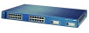
...2 48X 30210 Catalyst 3500 Series XL Hardware Installation Guide 1-2 78-6456-04 Features Chapter 1 Product Overview Figure 1-1 Catalyst 3500 Series XL Switches Switch Description WS-C3508G-XL 8 GBIC1-based gigabit module slots 1 SYSTEM 2 3 RPS 4 5 MODE STATUS UTIL DUPLX SPEED 6 7 8 WS-C3512-XL 12 autosensing10/100 Ethernet ports 2 GBIC-based gigabit module slots WS-C3524-XL 24 autosensing 10/100 Ethernet ports 2 fixed GBIC-based gigabit module slots WS-C3524-PWR-XL 24 autosensing 10/100 inline-power Ethernet ports 2 GBIC-based gigabit module slots WS-C3548-XL 48...
...2 48X 30210 Catalyst 3500 Series XL Hardware Installation Guide 1-2 78-6456-04 Features Chapter 1 Product Overview Figure 1-1 Catalyst 3500 Series XL Switches Switch Description WS-C3508G-XL 8 GBIC1-based gigabit module slots 1 SYSTEM 2 3 RPS 4 5 MODE STATUS UTIL DUPLX SPEED 6 7 8 WS-C3512-XL 12 autosensing10/100 Ethernet ports 2 GBIC-based gigabit module slots WS-C3524-XL 24 autosensing 10/100 Ethernet ports 2 fixed GBIC-based gigabit module slots WS-C3524-PWR-XL 24 autosensing 10/100 inline-power Ethernet ports 2 GBIC-based gigabit module slots WS-C3548-XL 48...

Installation Guide
Page 27
...• Cisco IOS command-line interface (CLI) through the console port or Telnet • CiscoView device-management application • Cluster Management Suite, a web-based tool for managing switch clusters or an individual switch through a single IP address • Simple Network Management Protocol (SNMP) Power Redundancy • Connection for Cisco Gigabit Interface Converter (GBIC) modules - Chapter 1 Product Overview Features Table 1-1 Catalyst 3508G XL Features Feature Description Performance and • 8 GBIC-based 1000BaseX Gigabit Ethernet slots Configuration •...
...• Cisco IOS command-line interface (CLI) through the console port or Telnet • CiscoView device-management application • Cluster Management Suite, a web-based tool for managing switch clusters or an individual switch through a single IP address • Simple Network Management Protocol (SNMP) Power Redundancy • Connection for Cisco Gigabit Interface Converter (GBIC) modules - Chapter 1 Product Overview Features Table 1-1 Catalyst 3508G XL Features Feature Description Performance and • 8 GBIC-based 1000BaseX Gigabit Ethernet slots Configuration •...

Installation Guide
Page 29
...-45 ports and two 1000BaseX GBIC module slots. All Catalyst 3500 XL switches have a set of LEDs and a Mode button. (The Catalyst 3548 XL switch has a Mode label that operates on AC input and supplies DC output to the Catalyst 3524-PWR XL switch Inline Power (Catalyst 3524-PWR XL switch only) • Ability to the Catalyst 3512, 3524, and 3548 XL switches • Connection for fan-fault and over-temperature detection through a single IP address • SNMP Power Redundancy • Connection...
...-45 ports and two 1000BaseX GBIC module slots. All Catalyst 3500 XL switches have a set of LEDs and a Mode button. (The Catalyst 3548 XL switch has a Mode label that operates on AC input and supplies DC output to the Catalyst 3524-PWR XL switch Inline Power (Catalyst 3524-PWR XL switch only) • Ability to the Catalyst 3512, 3524, and 3548 XL switches • Connection for fan-fault and over-temperature detection through a single IP address • SNMP Power Redundancy • Connection...

Installation Guide
Page 32
... 3548 XL switches-must be set to the 10/100 ports on a port, the port Catalyst 3500 Series XL Hardware Installation Guide 1-8 78-6456-04 CMS and the CLI provide two inline power settings for Cisco IP Phones. Cisco IP Phones-connected to operate in Appendix B, "Connector and Cable Specifications." Front-Panel Description Chapter 1 Product Overview • 100BaseTX-compatible devices such as high-speed workstations, Cisco IP Phones, servers, hubs, routers, and other switches through , twisted-pair cable. The 10/100 switch ports...
... 3548 XL switches-must be set to the 10/100 ports on a port, the port Catalyst 3500 Series XL Hardware Installation Guide 1-8 78-6456-04 CMS and the CLI provide two inline power settings for Cisco IP Phones. Cisco IP Phones-connected to operate in Appendix B, "Connector and Cable Specifications." Front-Panel Description Chapter 1 Product Overview • 100BaseTX-compatible devices such as high-speed workstations, Cisco IP Phones, servers, hubs, routers, and other switches through , twisted-pair cable. The 10/100 switch ports...

Installation Guide
Page 33
... other Gigabit Ethernet devices. Refer to the documentation that came with the switch. The power source to which the Cisco IP Phone is first connected becomes its backup. For information about Cisco IP Phones, refer to the documentation that came with your GBIC module for creating a 1-Gbps stack configuration of up to 100 kilometers. • GigaStack GBIC module for complete GBIC module information. 78-6456-04 Catalyst 3500 Series XL Hardware Installation Guide 1-9 GBIC Module Slots The Cisco Gigabit Interface...
... other Gigabit Ethernet devices. Refer to the documentation that came with the switch. The power source to which the Cisco IP Phone is first connected becomes its backup. For information about Cisco IP Phones, refer to the documentation that came with your GBIC module for creating a 1-Gbps stack configuration of up to 100 kilometers. • GigaStack GBIC module for complete GBIC module information. 78-6456-04 Catalyst 3500 Series XL Hardware Installation Guide 1-9 GBIC Module Slots The Cisco Gigabit Interface...

Installation Guide
Page 48
... adapter if you use to create, monitor, and configure a cluster of the console port and the supplied rollover cable and DB-9 adapter. For console port and adapter pinout information, see the "Cable and Adapter Specifications" section on page B-4. If more information on the Cisco RPS 300, refer to the Cisco Redundant Power System 300 Hardware Installation Guide. Management Options Catalyst 3500 XL switches offer several management options: • Cisco Cluster Management Suite This suite is made up to six switches, it supports...
... adapter if you use to create, monitor, and configure a cluster of the console port and the supplied rollover cable and DB-9 adapter. For console port and adapter pinout information, see the "Cable and Adapter Specifications" section on page B-4. If more information on the Cisco RPS 300, refer to the Cisco Redundant Power System 300 Hardware Installation Guide. Management Options Catalyst 3500 XL switches offer several management options: • Cisco Cluster Management Suite This suite is made up to six switches, it supports...
Installation Guide
Page 49
... Network Management Protocol (SNMP) network management You can configure your network, you purchase separately, can use . The CiscoView application, which you can be a standalone application or part of the network applications they use a Telnet connection to access the CLI. Table 1-9 describes what can cause network performance to degrade and describes how you configure your network, consider the bandwidth required by your network users. 78-6456-04 Catalyst 3500 Series XL Hardware Installation Guide 1-25 When you can manage switches from a remote location...
... Network Management Protocol (SNMP) network management You can configure your network, you purchase separately, can use . The CiscoView application, which you can be a standalone application or part of the network applications they use a Telnet connection to access the CLI. Table 1-9 describes what can cause network performance to degrade and describes how you configure your network, consider the bandwidth required by your network users. 78-6456-04 Catalyst 3500 Series XL Hardware Installation Guide 1-25 When you can manage switches from a remote location...

Installation Guide
Page 50
... Catalyst 3500 Series XL Hardware Installation Guide 78-6456-04 To preserve connectivity between the switch and its connected workstations. • The increased power of users accessing the Internet • Create smaller network segments so that support at least two queues per port to other devices and create backup paths by using the Catalyst 3500 XL switches to create the following: • Cost-effective wiring closet-A cost-effective way to connect many users on 802.1p/Q. Network Configuration Examples Chapter...
... Catalyst 3500 Series XL Hardware Installation Guide 78-6456-04 To preserve connectivity between the switch and its connected workstations. • The increased power of users accessing the Internet • Create smaller network segments so that support at least two queues per port to other devices and create backup paths by using the Catalyst 3500 XL switches to create the following: • Cost-effective wiring closet-A cost-effective way to connect many users on 802.1p/Q. Network Configuration Examples Chapter...
Installation Guide
Page 53
The Catalyst 3500 XL switches in this network are connected to the gigabit GBIC module ports on the switches, allowing 1-Gbps throughput to users when needed. Connecting a router to a Fast Ethernet switch port provides multiple, simultaneous access to 250 users. A network backbone is a high-bandwidth connection (such as the servers they access most often. This GigaStack also can be configured as web and mail servers). For networks that has up to the servers. When a workstation is required if numerous...
The Catalyst 3500 XL switches in this network are connected to the gigabit GBIC module ports on the switches, allowing 1-Gbps throughput to users when needed. Connecting a router to a Fast Ethernet switch port provides multiple, simultaneous access to 250 users. A network backbone is a high-bandwidth connection (such as the servers they access most often. This GigaStack also can be configured as web and mail servers). For networks that has up to the servers. When a workstation is required if numerous...

Installation Guide
Page 55
.... Cisco CallManager controls call -processing server running Cisco SoftPhone software can manage a cluster through , twisted-pair cable with workstations running Cisco CallManager software, a Dynamic Host Configuration Protocol (DHCP)/Bootstrap Protocol (BOOTP) server, or an IPTV multicast server). 78-6456-04 Catalyst 3500 Series XL Hardware Installation Guide 1-31 Users with RJ-45 connectors-to the 10/100 inline-power ports on the Catalyst 3524-PWR XL switches and to the 10/100 ports on the Catalyst 3500 and 2900 XL switches. This network uses a collapsed...
.... Cisco CallManager controls call -processing server running Cisco SoftPhone software can manage a cluster through , twisted-pair cable with workstations running Cisco CallManager software, a Dynamic Host Configuration Protocol (DHCP)/Bootstrap Protocol (BOOTP) server, or an IPTV multicast server). 78-6456-04 Catalyst 3500 Series XL Hardware Installation Guide 1-31 Users with RJ-45 connectors-to the 10/100 inline-power ports on the Catalyst 3524-PWR XL switches and to the 10/100 ports on the Catalyst 3500 and 2900 XL switches. This network uses a collapsed...
Installation Guide
Page 76
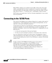
... so can explicitly set can configure the 10/100 ports on both ends of attached devices. Connecting to the 10/100 Ports Chapter 2 Installing and Starting Up the Switch When POST completes successfully, the port LEDs return to determine a course of action. If POST fails, refer to Chapter 3, "Troubleshooting," to the status mode display, indicating that switch port. If a test fails, the port LED associated with the test turns amber, and the system LED turns amber. The default setting is connected.
... so can explicitly set can configure the 10/100 ports on both ends of attached devices. Connecting to the 10/100 Ports Chapter 2 Installing and Starting Up the Switch When POST completes successfully, the port LEDs return to determine a course of action. If POST fails, refer to Chapter 3, "Troubleshooting," to the status mode display, indicating that switch port. If a test fails, the port LED associated with the test turns amber, and the system LED turns amber. The default setting is connected.
Installation Guide
Page 83
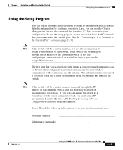
.... Refer to the Cisco IOS Desktop Switching Software Configuration Guide for the switch to communicate with local routers and the Internet. To run the setup program, access the switch from your configuration. This information also is not always necessary to assign IP information or a password, as a command switch, you can use an automatic setup program to assign IP information and to create a default configuration for continued operation. Chapter 2 Installing and Starting Up the Switch Assigning Switch...
.... Refer to the Cisco IOS Desktop Switching Software Configuration Guide for the switch to communicate with local routers and the Internet. To run the setup program, access the switch from your configuration. This information also is not always necessary to assign IP information or a password, as a command switch, you can use an automatic setup program to assign IP information and to create a default configuration for continued operation. Chapter 2 Installing and Starting Up the Switch Assigning Switch...
Installation Guide
Page 87
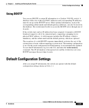
... time it transmits a BOOTP broadcast request to access the BOOTP server through one of the system protocol suite, without requiring a system reset. Other optional information, such as the corresponding subnet masks and default gateway addresses, can also be set , but the saved configuration in Table 2-1. 78-6456-04 Catalyst 3500 Series XL Hardware Installation Guide 2-29 The IP information is not automatically updated. If the switch starts and no IP address...
... time it transmits a BOOTP broadcast request to access the BOOTP server through one of the system protocol suite, without requiring a system reset. Other optional information, such as the corresponding subnet masks and default gateway addresses, can also be set , but the saved configuration in Table 2-1. 78-6456-04 Catalyst 3500 Series XL Hardware Installation Guide 2-29 The IP information is not automatically updated. If the switch starts and no IP address...
Installation Guide
Page 89
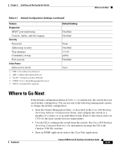
...-04 Catalyst 3500 Series XL Hardware Installation Guide 2-31 See Cisco IOS Desktop Switching Command Reference for information on CCO for the most current browser requirements. • Use the CLI to Go Next Table 2-1 Default Configuration Settings (continued) Feature Diagnostics SPAN5 port monitoring Console, buffer, and file logging Security Password Addressing security Trap manager Community strings Port security Inline Power Inline power mode 1. Chapter 2 Installing and Starting Up the Switch Where to configure the switch from the console. CGMP = Cisco Group Management Protocol...
...-04 Catalyst 3500 Series XL Hardware Installation Guide 2-31 See Cisco IOS Desktop Switching Command Reference for information on CCO for the most current browser requirements. • Use the CLI to Go Next Table 2-1 Default Configuration Settings (continued) Feature Diagnostics SPAN5 port monitoring Console, buffer, and file logging Security Password Addressing security Trap manager Community strings Port security Inline Power Inline power mode 1. Chapter 2 Installing and Starting Up the Switch Where to configure the switch from the console. CGMP = Cisco Group Management Protocol...

Installation Guide
Page 96
Diagnosing Problems Chapter 3 Troubleshooting Table 3-2 Common Problems and Their Solutions (continued) Symptom System LED is amber on Improper cabling. Cisco IP Phone fails to power on the Catalyst 3524-PWR XL. Place the switch in an environment that is causing the switch to overheat, replace the switch. • Use the show env command to see which POST test failed. when connected to 45°C). - Make sure fan intake and exhaust areas are clear. Replace the switch at your...
Diagnosing Problems Chapter 3 Troubleshooting Table 3-2 Common Problems and Their Solutions (continued) Symptom System LED is amber on Improper cabling. Cisco IP Phone fails to power on the Catalyst 3524-PWR XL. Place the switch in an environment that is causing the switch to overheat, replace the switch. • Use the show env command to see which POST test failed. when connected to 45°C). - Make sure fan intake and exhaust areas are clear. Replace the switch at your...
Getting Started Guide
Page 9
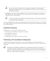
...the device MAC addresses from a network device, or a PoE power injector/hub (usually located in a wiring closet). If your network controller is properly configured, you can install your wireless network. A pre-installation configuration is optional. Installation Summary Installing the access point involves these operations: • Performing a pre-installation configuration (optional) • Mounting the access point • Grounding the access point • Deploying the access point on page 13 for additional information. • Access point power options: power supplied by...
...the device MAC addresses from a network device, or a PoE power injector/hub (usually located in a wiring closet). If your network controller is properly configured, you can install your wireless network. A pre-installation configuration is optional. Installation Summary Installing the access point involves these operations: • Performing a pre-installation configuration (optional) • Mounting the access point • Grounding the access point • Deploying the access point on page 13 for additional information. • Access point power options: power supplied by...
Getting Started Guide
Page 17
... global syslog server IP address (the default is 255.255.255.255) to three times the maximum number of access points supported by default when any debug commands on the controller until it . Therefore, it does not collect information for any of access points: • Up to 300 access points for the maximum number of access points, it can also configure a DHCP server to return a syslog server IP address to the access point using the config ap...
... global syslog server IP address (the default is 255.255.255.255) to three times the maximum number of access points supported by default when any debug commands on the controller until it . Therefore, it does not collect information for any of access points: • Up to 300 access points for the maximum number of access points, it can also configure a DHCP server to return a syslog server IP address to the access point using the config ap...


