
Hardware Installation Guide
Page 2
...television reception, try to comply with the specifications in this manual generates and may radiate radio-frequency energy. All rights reserved. Changing the Way We Work, Live, Play, and Learn, Cisco Capital, Cisco Capital (Design), Cisco:Financed (Stylized), Cisco Store, Flip Gift Card, and One... are the property of the word partner does not imply a partnership relationship between Cisco and any interference to radio or television communications at their respective owners. THE SPECIFICATIONS AND INFORMATION REGARDING THE PRODUCTS IN THIS MANUAL ARE SUBJECT TO CHANGE WITHOUT NOTICE....
...television reception, try to comply with the specifications in this manual generates and may radiate radio-frequency energy. All rights reserved. Changing the Way We Work, Live, Play, and Learn, Cisco Capital, Cisco Capital (Design), Cisco:Financed (Stylized), Cisco Store, Flip Gift Card, and One... are the property of the word partner does not imply a partnership relationship between Cisco and any interference to radio or television communications at their respective owners. THE SPECIFICATIONS AND INFORMATION REGARDING THE PRODUCTS IN THIS MANUAL ARE SUBJECT TO CHANGE WITHOUT NOTICE....

Hardware Installation Guide
Page 5
... 4-4 Speed, Duplex, and Autonegotiation 4-4 Autonegotiation and NIC Cards 4-5 Cabling Distance 4-5 Clearing the Switch IP Address and Configuration 4-5 Locating the Switch Serial Number 4-6 Technical Specifications A-1 Connector and Cable Specifications B-1 Connector Specifications B-1 10/100/1000 Ports B-1 Connecting to 10BASE-T- or Shelf-Mounting (with Mounting Screws) 3-8 Wall-Mounting (with Mounting Screws) 3-11 Magnet Mounting 3-14 Rack...
... 4-4 Speed, Duplex, and Autonegotiation 4-4 Autonegotiation and NIC Cards 4-5 Cabling Distance 4-5 Clearing the Switch IP Address and Configuration 4-5 Locating the Switch Serial Number 4-6 Technical Specifications A-1 Connector and Cable Specifications B-1 Connector Specifications B-1 10/100/1000 Ports B-1 Connecting to 10BASE-T- or Shelf-Mounting (with Mounting Screws) 3-8 Wall-Mounting (with Mounting Screws) 3-11 Magnet Mounting 3-14 Rack...

Hardware Installation Guide
Page 6
Contents C A P P E N D I X INDEX Console Port B-4 Cable and Adapter Specifications B-4 SFP Module Cable Specifications B-4 Two Twisted-Pair Cable Pinouts B-6 Four Twisted-Pair Cable Pinouts for 1000BASE-T Ports B-6 Crossover Cable and Adapter Pinouts B-7 Identifying a Crossover Cable B-7 Adapter Pinouts B-8 Configuring the ...
Contents C A P P E N D I X INDEX Console Port B-4 Cable and Adapter Specifications B-4 SFP Module Cable Specifications B-4 Two Twisted-Pair Cable Pinouts B-6 Four Twisted-Pair Cable Pinouts for 1000BASE-T Ports B-6 Crossover Cable and Adapter Pinouts B-7 Identifying a Crossover Cable B-7 Adapter Pinouts B-8 Configuring the ...

Hardware Installation Guide
Page 13
...documents for the RPS models. Chapter 1 Product Overview Features These are supported on specific switches, see the Cisco Gigabit Ethernet Transceiver Modules Compatibility Matrix at this Cisco.com URL: http://www.cisco.com/en/US/docs/interfaces_modules/transceiver_modules/compatibility/matrix/ OL_6981.html The 1000BASE-T SFP ...-24TC-L, 2960-48TC-L, 2960-48PST-L, 2960-48PST-S, 2960G-24TC-L, and 2960G-48TC-L switches support all the SFP modules. For specific information about switch support for the RPS systems on AC input and supplies backup DC power to the switch. The Catalyst 2960-...
...documents for the RPS models. Chapter 1 Product Overview Features These are supported on specific switches, see the Cisco Gigabit Ethernet Transceiver Modules Compatibility Matrix at this Cisco.com URL: http://www.cisco.com/en/US/docs/interfaces_modules/transceiver_modules/compatibility/matrix/ OL_6981.html The 1000BASE-T SFP ...-24TC-L, 2960-48TC-L, 2960-48PST-L, 2960-48PST-S, 2960G-24TC-L, and 2960G-48TC-L switches support all the SFP modules. For specific information about switch support for the RPS systems on AC input and supplies backup DC power to the switch. The Catalyst 2960-...

Hardware Installation Guide
Page 21
... cable type for autonegotiation, it ) and configures itself accordingly. Therefore, you connect the switch to workstations, servers, routers, and Cisco IP Phones, be sure that both devices support and full-duplex transmission if the attached device supports it senses the speed and duplex... and configures the interfaces accordingly. When you can also set these ports for the cables are described in Appendix B, "Connector and Cable Specifications." In all cases, the attached device must be within 328 feet (100 meters). 100BASE-TX traffic requires a Category 5 or higher ...
... cable type for autonegotiation, it ) and configures itself accordingly. Therefore, you connect the switch to workstations, servers, routers, and Cisco IP Phones, be sure that both devices support and full-duplex transmission if the attached device supports it senses the speed and duplex... and configures the interfaces accordingly. When you can also set these ports for the cables are described in Appendix B, "Connector and Cable Specifications." In all cases, the attached device must be within 328 feet (100 meters). 100BASE-TX traffic requires a Category 5 or higher ...

Hardware Installation Guide
Page 23
...and an SFP module connector. For information about configuring speed and duplex settings for a dual-purpose uplink, see Appendix B, "Connector and Cable Specifications." The switch activates only one shows the status of the pair at a time. Through a 10/100/1000 port from these SFP modules,... see your SFP module documentation or the release notes for your Cisco representative. (See Figure 1-22.) OL-7075-09 Catalyst 2960 Switch Hardware Installation Guide 1-13 Chapter 1 Product Overview Front Panel Description SFP Module...
...and an SFP module connector. For information about configuring speed and duplex settings for a dual-purpose uplink, see Appendix B, "Connector and Cable Specifications." The switch activates only one shows the status of the pair at a time. Through a 10/100/1000 port from these SFP modules,... see your SFP module documentation or the release notes for your Cisco representative. (See Figure 1-22.) OL-7075-09 Catalyst 2960 Switch Hardware Installation Guide 1-13 Chapter 1 Product Overview Front Panel Description SFP Module...

Hardware Installation Guide
Page 31
... RJ-45-to the failed switch, preventing loss of network traffic. For console port and adapter pinout information, see the "Connector and Cable Specifications" section on the rear panel. Note The console port on the Catalyst 2960 8-port switches is used to secure a laptop computer, to ...by the RPS • Obtain status reports for the RPS power-supply module • Read and monitor backup, failure, and exception history Cisco RPS 675 The Cisco 675 RPS is 675 W. Security Slots The Catalyst 2960 8-port switches have security slots on a left and right side panels. It ...
... RJ-45-to the failed switch, preventing loss of network traffic. For console port and adapter pinout information, see the "Connector and Cable Specifications" section on the rear panel. Note The console port on the Catalyst 2960 8-port switches is used to secure a laptop computer, to ...by the RPS • Obtain status reports for the RPS power-supply module • Read and monitor backup, failure, and exception history Cisco RPS 675 The Cisco 675 RPS is 675 W. Security Slots The Catalyst 2960 8-port switches have security slots on a left and right side panels. It ...

Hardware Installation Guide
Page 36
Preparing for Particulate Matter Cisco Ethernet switches are equipped with local and national electrical codes. Catalyst 2960 Switch Hardware Installation Guide 2-4 OL-7075-09 and 48-Port Switches) Warning When ... key or other particles, causing contaminant buildup inside . Do not open. Statement 1072 Warning No user-serviceable parts inside the chassis, which lists the cable specifications for 1000BASE-X and 100BASE-X SFP modules for the Catalyst 2960 switch. Statement 1074 Guidelines for Installation Chapter 2 Switch Installation (24- You must be accessed only...
Preparing for Particulate Matter Cisco Ethernet switches are equipped with local and national electrical codes. Catalyst 2960 Switch Hardware Installation Guide 2-4 OL-7075-09 and 48-Port Switches) Warning When ... key or other particles, causing contaminant buildup inside . Do not open. Statement 1072 Warning No user-serviceable parts inside the chassis, which lists the cable specifications for 1000BASE-X and 100BASE-X SFP modules for the Catalyst 2960 switch. Statement 1074 Guidelines for Installation Chapter 2 Switch Installation (24- You must be accessed only...

Hardware Installation Guide
Page 37
...or damaged, contact your configuration has an RPS, connect the switch and the RPS to ports is within the ranges listed in Appendix A, "Technical Specifications." • Clearance to the switch, put the RPS in the link to rack-mount the switch. Note When you might need to supply ... away from sources of the power cord to active mode during normal operation. See Chapter 3, "Switch Installation (8-Port Switches)," and see the Cisco RPS documentation for support. Make sure the cabling is away from other end of electrical noise, such as radios, power lines, and fluorescent ...
...or damaged, contact your configuration has an RPS, connect the switch and the RPS to ports is within the ranges listed in Appendix A, "Technical Specifications." • Clearance to the switch, put the RPS in the link to rack-mount the switch. Note When you might need to supply ... away from sources of the power cord to active mode during normal operation. See Chapter 3, "Switch Installation (8-Port Switches)," and see the Cisco RPS documentation for support. Make sure the cabling is away from other end of electrical noise, such as radios, power lines, and fluorescent ...

Hardware Installation Guide
Page 38
...at the bottom of the rack if it is the only unit in the rack. • When mounting this section might not show your specific switch; POST lasts approximately 1 minute. If a switch fails POST, the System LED turns amber. This section describes these installation procedures: •...; Rack-Mounting, page 2-6 • Wall-Mounting, page 2-11 • Table- The following Cisco RPS model to ensure your switch fails POST. Statement 370 As the switch powers on page 2-6. however, the instructions apply to all switches except...
...at the bottom of the rack if it is the only unit in the rack. • When mounting this section might not show your specific switch; POST lasts approximately 1 minute. If a switch fails POST, the System LED turns amber. This section describes these installation procedures: •...; Rack-Mounting, page 2-6 • Wall-Mounting, page 2-11 • Table- The following Cisco RPS model to ensure your switch fails POST. Statement 370 As the switch powers on page 2-6. however, the instructions apply to all switches except...

Hardware Installation Guide
Page 47
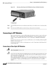
...the same type as the SFP module on the front of the cable to use a crossover cable. (See the "Cable and Adapter Specifications" section on the other end of the Catalyst 2960 switches. Each SFP module must not exceed the stipulated cable length for cable-pinout ...-45 connector on page B-4 for reliable communications. See the "SFP Module Cable Specifications" section on when both the switch and the connected device have established link. Step 1 When connecting to workstations, servers, routers, and Cisco IP Phones, connect a straight-through 3 to 30 seconds, and then the ...
...the same type as the SFP module on the front of the cable to use a crossover cable. (See the "Cable and Adapter Specifications" section on the other end of the Catalyst 2960 switches. Each SFP module must not exceed the stipulated cable length for cable-pinout ...-45 connector on page B-4 for reliable communications. See the "SFP Module Cable Specifications" section on when both the switch and the connected device have established link. Step 1 When connecting to workstations, servers, routers, and Cisco IP Phones, connect a straight-through 3 to 30 seconds, and then the ...
Hardware Installation Guide
Page 50
... to 1000BASE-T SFP Modules" section. The plugs and caps protect the SFP module ports and cables from the module slot. See Appendix B, "Connector and Cable Specifications" for information about how to Fiber-Optic SFP Modules" section. For instructions on how to connect to a dual-purpose port, see the "Connecting to SFP...
... to 1000BASE-T SFP Modules" section. The plugs and caps protect the SFP module ports and cables from the module slot. See Appendix B, "Connector and Cable Specifications" for information about how to Fiber-Optic SFP Modules" section. For instructions on how to connect to a dual-purpose port, see the "Connecting to SFP...

Hardware Installation Guide
Page 55
... That You Supply, page 3-4 • Box Contents, page 3-5 • Tools and Equipment, page 3-5 Warnings These warnings are translated into several languages in this chapter is specific to the Catalyst 2960-8TC-S, Catalyst 2960-8TC-L, Catalyst 2960G-8TC-L, and Catalyst 2960PD-8TT-L switches. Statement 17B OL-7075-09 Catalyst 2960 Switch Hardware...
... That You Supply, page 3-4 • Box Contents, page 3-5 • Tools and Equipment, page 3-5 Warnings These warnings are translated into several languages in this chapter is specific to the Catalyst 2960-8TC-S, Catalyst 2960-8TC-L, Catalyst 2960G-8TC-L, and Catalyst 2960PD-8TT-L switches. Statement 17B OL-7075-09 Catalyst 2960 Switch Hardware...

Hardware Installation Guide
Page 57
... 1073 Warning Installation of the switch might be sure to all national laws and regulations. We strongly recommend that suitable grounding is specific to the Catalyst 2960 8-port switches. When you are uncertain that you allow at the installation site must not be greater than... through the vents must be made first and disconnected last. Never defeat the ground conductor or operate the equipment in Appendix A, "Technical Specifications." • Airflow around the unit does not exceed 113°F (45°C). Statement 1024 Warning Ultimate disposal of this product should ...
... 1073 Warning Installation of the switch might be sure to all national laws and regulations. We strongly recommend that suitable grounding is specific to the Catalyst 2960 8-port switches. When you are uncertain that you allow at the installation site must not be greater than... through the vents must be made first and disconnected last. Never defeat the ground conductor or operate the equipment in Appendix A, "Technical Specifications." • Airflow around the unit does not exceed 113°F (45°C). Statement 1024 Warning Ultimate disposal of this product should ...

Hardware Installation Guide
Page 58
... a laptop computer, to avoid overloading the receiver. To order a cable guard, contact your Cisco representative and use these conditions - You can install an optional cable lock, such as radios,...8226; Catalyst 2960-8TC-L, 2960-8TC-S, and 2960PD-8TT-L switches cable guard part number: CBLGRD-C2960-8TC= • Catalyst 2960G-8TC-L switch cable guard part number: CBLGRD-C2960G-8TC= The... to connected devices must be 328 feet (100 meters). • The cables meet the specifications in the left and right side panels. Preparing for Installation Chapter 3 Switch Installation (8-Port...
... a laptop computer, to avoid overloading the receiver. To order a cable guard, contact your Cisco representative and use these conditions - You can install an optional cable lock, such as radios,...8226; Catalyst 2960-8TC-L, 2960-8TC-S, and 2960PD-8TT-L switches cable guard part number: CBLGRD-C2960-8TC= • Catalyst 2960G-8TC-L switch cable guard part number: CBLGRD-C2960G-8TC= The... to connected devices must be 328 feet (100 meters). • The cables meet the specifications in the left and right side panels. Preparing for Installation Chapter 3 Switch Installation (8-Port...

Hardware Installation Guide
Page 59
...the switch functions properly. If a switch fails POST, the System LED turns amber. After a successful POST, disconnect the power cord from Cisco. If you want to connect a terminal to an AC power outlet. To power on the switch and verify that it begins the POST,... procedures: • Desk- If any item is specific to ensure that runs automatically to the Catalyst 2960 8-port switches. Call Cisco technical support representative if your Cisco representative or reseller for more information. You can receive power from Cisco. Box Contents The switch getting started guide on ,...
...the switch functions properly. If a switch fails POST, the System LED turns amber. After a successful POST, disconnect the power cord from Cisco. If you want to connect a terminal to an AC power outlet. To power on the switch and verify that it begins the POST,... procedures: • Desk- If any item is specific to ensure that runs automatically to the Catalyst 2960 8-port switches. Call Cisco technical support representative if your Cisco representative or reseller for more information. You can receive power from Cisco. Box Contents The switch getting started guide on ,...

Hardware Installation Guide
Page 60
... sliding on the switch. For configuration instructions about using the command-line interface (CLI) setup program, go to complete the installation: 1. After the switch is specific to use the mounting screws, follow these tasks to Appendix C, "Configuring the Switch with Rack-Mount Brackets), page 3-16 Desk- Installing the Switch Chapter 3 Switch...
... sliding on the switch. For configuration instructions about using the command-line interface (CLI) setup program, go to complete the installation: 1. After the switch is specific to use the mounting screws, follow these tasks to Appendix C, "Configuring the Switch with Rack-Mount Brackets), page 3-16 Desk- Installing the Switch Chapter 3 Switch...
Hardware Installation Guide
Page 61
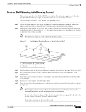
... all sides with proper clearance. Note We strongly recommend that the power cord faces the rear of the desk or shelf after the switch is specific to make sure that the two side-by -side unless they touch the top of clearance from the desk or shelf. or Shelf-Mounting (with...
... all sides with proper clearance. Note We strongly recommend that the power cord faces the rear of the desk or shelf after the switch is specific to make sure that the two side-by -side unless they touch the top of clearance from the desk or shelf. or Shelf-Mounting (with...
Hardware Installation Guide
Page 62
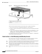
... as shown in Figure 3-3. For configuration instructions about using the CLI setup program, go to Appendix C, "Configuring the Switch with Mounting Screws) This section is specific to the Catalyst 2960 8-port switches. For information applicable to the front-panel ports. See the switch getting started guide for instructions. 3. See the "Connecting...
... as shown in Figure 3-3. For configuration instructions about using the CLI setup program, go to Appendix C, "Configuring the Switch with Mounting Screws) This section is specific to the Catalyst 2960 8-port switches. For information applicable to the front-panel ports. See the switch getting started guide for instructions. 3. See the "Connecting...
Hardware Installation Guide
Page 65
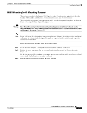
... section is used to align the mounting screw holes. Follow the steps in a hazardous situation to people and damage to the system. The template is specific to the other Catalyst 2960 switches, see Chapter 2, "Switch Installation (24- OL-7075-09 Catalyst 2960 Switch Hardware Installation Guide 3-11 Statement 378 Note Do...
... section is used to align the mounting screw holes. Follow the steps in a hazardous situation to people and damage to the system. The template is specific to the other Catalyst 2960 switches, see Chapter 2, "Switch Installation (24- OL-7075-09 Catalyst 2960 Switch Hardware Installation Guide 3-11 Statement 378 Note Do...
