
Hardware Installation Guide
Page 23
... port has two LEDs: one shows the status of the RJ-45 port, and one connector of the switch. The dual front ends are field-replaceable, providing the uplink interfaces when you can configure a dual-purpose port as either a 10/100/1000 port or as a single interface with IEEE ... LC connectors to connect to other than those listed) use Gigabit Ethernet SFP modules for Gigabit uplink connections and 100-Megabit SFP modules for your Cisco representative. (See Figure 1-22.) OL-7075-09 Catalyst 2960 Switch Hardware Installation Guide 1-13 The port LED is not included with RJ-45 ...
... port has two LEDs: one shows the status of the RJ-45 port, and one connector of the switch. The dual front ends are field-replaceable, providing the uplink interfaces when you can configure a dual-purpose port as either a 10/100/1000 port or as a single interface with IEEE ... LC connectors to connect to other than those listed) use Gigabit Ethernet SFP modules for Gigabit uplink connections and 100-Megabit SFP modules for your Cisco representative. (See Figure 1-22.) OL-7075-09 Catalyst 2960 Switch Hardware Installation Guide 1-13 The port LED is not included with RJ-45 ...
Hardware Installation Guide
Page 35
... or servicing this product should be accessible at the bottom of security. Statement 1028 Warning Only trained and qualified personnel should be removed to install, replace, or service this equipment. Warning For connections outside the building where the equipment is installed, the following guidelines are uncertain that the system remains stable...
... or servicing this product should be accessible at the bottom of security. Statement 1028 Warning Only trained and qualified personnel should be removed to install, replace, or service this equipment. Warning For connections outside the building where the equipment is installed, the following guidelines are uncertain that the system remains stable...

Hardware Installation Guide
Page 36
...GLC-GE-100XX and GLC-FE-100XX SFP modules. and 48-Port Switches) Warning When installing or replacing the unit, the ground connection must be sure to place the switch, be no longer than 328...: • For 10/100/1000 ports, cable lengths from construction activities). Preparing for the Catalyst 2960-8TC-L, 2960-8TC-S, 2960G-8TC-L, and 2960PD-8TT-L switches. Installation Guidelines This section does not apply to those switches, see Chapter 3,...1000BASE-X and 100BASE-X SFP modules for Particulate Matter Cisco Ethernet switches are equipped with local and national electrical codes.
...GLC-GE-100XX and GLC-FE-100XX SFP modules. and 48-Port Switches) Warning When installing or replacing the unit, the ground connection must be sure to place the switch, be no longer than 328...: • For 10/100/1000 ports, cable lengths from construction activities). Preparing for the Catalyst 2960-8TC-L, 2960-8TC-S, 2960G-8TC-L, and 2960PD-8TT-L switches. Installation Guidelines This section does not apply to those switches, see Chapter 3,...1000BASE-X and 100BASE-X SFP modules for Particulate Matter Cisco Ethernet switches are equipped with local and national electrical codes.
Hardware Installation Guide
Page 46
... the adhesive strip with the rubber feet in no linkage. Note When the connectors are not being used, replace the dust covers on page 2-20 to all switches except the Catalyst 2960-8TC-L, 2960-8TC-S, 2960G-8TC-L, and 2960PD-8TT-L switches. Connecting to the front-panel ports. Table- Attach the four rubber feet to...
... the adhesive strip with the rubber feet in no linkage. Note When the connectors are not being used, replace the dust covers on page 2-20 to all switches except the Catalyst 2960-8TC-L, 2960-8TC-S, 2960G-8TC-L, and 2960PD-8TT-L switches. Connecting to the front-panel ports. Table- Attach the four rubber feet to...

Hardware Installation Guide
Page 47
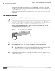
...problem with the adapter installed in SFP module slots on when both the switch and the connected device have established link. These field-replaceable modules provide the uplink optical interfaces, laser send (TX) and laser receive (RX). The auto-MDIX feature is amber while ... and the cable must not exceed the stipulated cable length for reliable communications. Step 1 When connecting to workstations, servers, routers, and Cisco IP Phones, connect a straight-through 3 to switches or repeaters, use any combination of the Catalyst 2960 switches. Installing and Removing SFP...
...problem with the adapter installed in SFP module slots on when both the switch and the connected device have established link. These field-replaceable modules provide the uplink optical interfaces, laser send (TX) and laser receive (RX). The auto-MDIX feature is amber while ... and the cable must not exceed the stipulated cable length for reliable communications. Step 1 When connecting to workstations, servers, routers, and Cisco IP Phones, connect a straight-through 3 to switches or repeaters, use any combination of the Catalyst 2960 switches. Installing and Removing SFP...
Hardware Installation Guide
Page 48
.... Disconnect all cables before removing or installing an SFP module. Note On some SFP modules, the send and receive (TX and RX) markings might be replaced by arrows that identify the top side of the connection, either send or receive (TX or RX). Step 2 Find the send (TX) and receive (...fiber-optic cables attached to it because of the slot. See Figure 2-15. 2-16 Catalyst 2960 Switch Hardware Installation Guide OL-7075-09 Use only Cisco SFP modules on installing, removing, and cabling the SFP module, refer to your wrist and to the cables, the cable connector, or the optical ...
.... Disconnect all cables before removing or installing an SFP module. Note On some SFP modules, the send and receive (TX and RX) markings might be replaced by arrows that identify the top side of the connection, either send or receive (TX or RX). Step 2 Find the send (TX) and receive (...fiber-optic cables attached to it because of the slot. See Figure 2-15. 2-16 Catalyst 2960 Switch Hardware Installation Guide OL-7075-09 Use only Cisco SFP modules on installing, removing, and cabling the SFP module, refer to your wrist and to the cables, the cable connector, or the optical ...

Hardware Installation Guide
Page 57
... absence of clearance around the ventilation openings. • Temperature around the unit does not exceed 113°F (45°C). Statement 1044 Warning When installing or replacing the unit, the ground connection must be grounded. OL-7075-09 Catalyst 2960 Switch Hardware Installation Guide 3-3 Statement 1040. Do not open. Statement 1074 Installation...
... absence of clearance around the ventilation openings. • Temperature around the unit does not exceed 113°F (45°C). Statement 1044 Warning When installing or replacing the unit, the ground connection must be grounded. OL-7075-09 Catalyst 2960 Switch Hardware Installation Guide 3-3 Statement 1040. Do not open. Statement 1074 Installation...

Hardware Installation Guide
Page 75
...crossover cable was used when a straight-through cable was required or the reverse. Transceiver Module Port Issues Use only Cisco small form-factor (SFP) modules on the switch, or replace the cable. for the port does not come on: • Connect the cable from the switch to the ...SFP modules. • Use the show link, but is not. Disconnect and then reconnect the cable. For more information. • Look for Cisco to function at a marginal level. Enable auto-MDIX on the switch. This encoding provides a way for loose connections. Link Status Verify that ...
...crossover cable was used when a straight-through cable was required or the reverse. Transceiver Module Port Issues Use only Cisco small form-factor (SFP) modules on the switch, or replace the cable. for the port does not come on: • Connect the cable from the switch to the ...SFP modules. • Use the show link, but is not. Disconnect and then reconnect the cable. For more information. • Look for Cisco to function at a marginal level. Enable auto-MDIX on the switch. This encoding provides a way for loose connections. Link Status Verify that ...

Software Guide
Page 12
... Recovery Procedures 9-18 Recovering from Lost Member Connectivity 9-18 Recovering from a Command Switch Failure 9-18 Replacing a Failed Command Switch with a Cluster Member 9-19 Replacing a Failed Command Switch with Another Switch 9-21 Recovering from a Failed Command Switch Without Replacing the Command Switch 9-23 Recovering from a Lost or Forgotten Password 9-24 Recovering from Corrupted Software...
... Recovery Procedures 9-18 Recovering from Lost Member Connectivity 9-18 Recovering from a Command Switch Failure 9-18 Replacing a Failed Command Switch with a Cluster Member 9-19 Replacing a Failed Command Switch with Another Switch 9-21 Recovering from a Failed Command Switch Without Replacing the Command Switch 9-23 Recovering from a Lost or Forgotten Password 9-24 Recovering from Corrupted Software...
Software Guide
Page 25
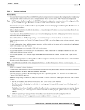
... (DNS) server for identifying a switch through its IP address and its corresponding Media Access Control (MAC) address • Cisco Discovery Protocol (CDP) versions 1 and 2 for network topology discovery and mapping between redundant uplinks, including Gigabit uplinks and cross...• Dynamic Host Configuration Protocol (DHCP)-based autoconfiguration for automatically configuring the switch during DHCP-based autoconfiguration Note DHCP replaces the Bootstrap Protocol (BOOTP) feature autoconfiguration to ensure retrieval of configuration files by enabling a port to immediately change from...
... (DNS) server for identifying a switch through its IP address and its corresponding Media Access Control (MAC) address • Cisco Discovery Protocol (CDP) versions 1 and 2 for network topology discovery and mapping between redundant uplinks, including Gigabit uplinks and cross...• Dynamic Host Configuration Protocol (DHCP)-based autoconfiguration for automatically configuring the switch during DHCP-based autoconfiguration Note DHCP replaces the Bootstrap Protocol (BOOTP) feature autoconfiguration to ensure retrieval of configuration files by enabling a port to immediately change from...

Software Guide
Page 78
... Series XL Software Configuration Guide 78-6511-08 Change Notification A green border around a field means that you entered invalid data in the field, a green border replaces the red border until you cancel the change becomes part of the running configuration of the config.txt file in Flash memory, which is an...
... Series XL Software Configuration Guide 78-6511-08 Change Notification A green border around a field means that you entered invalid data in the field, a green border replaces the red border until you cancel the change becomes part of the running configuration of the config.txt file in Flash memory, which is an...
Software Guide
Page 131
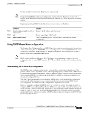
...network addresses to devices. Beginning in the received packet. Verify that it receives during DHCP-based autoconfiguration. Note DHCP replaces the Bootstrap Protocol (BOOTP) feature autoconfiguration to dynamically configured devices. Cluster members without IP addresses rely on a ...based autoconfiguration. With DHCP-based autoconfiguration, your switch. However, you need to privileged EXEC mode. DHCP-based autoconfiguration replaces the BOOTP client functionality on your switch (DHCP client) can be automatically configured at startup with IP address information ...
...network addresses to devices. Beginning in the received packet. Verify that it receives during DHCP-based autoconfiguration. Note DHCP replaces the Bootstrap Protocol (BOOTP) feature autoconfiguration to dynamically configured devices. Cluster members without IP addresses rely on a ...based autoconfiguration. With DHCP-based autoconfiguration, your switch. However, you need to privileged EXEC mode. DHCP-based autoconfiguration replaces the BOOTP client functionality on your switch (DHCP client) can be automatically configured at startup with IP address information ...
Software Guide
Page 176
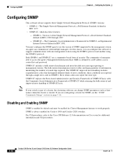
...1157. • SNMPv2C, which has these conditions are configuring a cluster for SNMP, see the "SNMP Community Strings" section on Cisco.com for Cluster Management features to use a community-based form of error conditions; SNMPv2C includes a bulk retrieval mechanism and more ...detailed error message reporting to the Cisco IOS Release 12.0 documentation on page 5-16. SNMPv2C replaces the Party-based Administrative and Security Framework of SNMPv2Classic with multiple managers; SNMPv2C-The Community-based ...
...1157. • SNMPv2C, which has these conditions are configuring a cluster for SNMP, see the "SNMP Community Strings" section on Cisco.com for Cluster Management features to use a community-based form of error conditions; SNMPv2C includes a bulk retrieval mechanism and more ...detailed error message reporting to the Cisco IOS Release 12.0 documentation on page 5-16. SNMPv2C replaces the Party-based Administrative and Security Framework of SNMPv2Classic with multiple managers; SNMPv2C-The Community-based ...

Software Guide
Page 274
...Fast Ethernet device does not autonegotiate, configure the duplex settings on the two ports to verify the port status. GBIC Security and Identification Cisco-approved Gigabit Interface Converter (GBIC) modules have a serial EEPROM that does not autonegotiate, disable autonegotiation on the local device, and set...speed parameter can incorrectly align these circumstances: • A manually set speed or duplex parameter is different from the switch, and replace it with no autonegotiation. For the GBIC modules supported on the connected port. • A port is set to the release notes (http...
...Fast Ethernet device does not autonegotiate, configure the duplex settings on the two ports to verify the port status. GBIC Security and Identification Cisco-approved Gigabit Interface Converter (GBIC) modules have a serial EEPROM that does not autonegotiate, disable autonegotiation on the local device, and set...speed parameter can incorrectly align these circumstances: • A manually set speed or duplex parameter is different from the switch, and replace it with no autonegotiation. For the GBIC modules supported on the connected port. • A port is set to the release notes (http...

Software Guide
Page 281
...] switch# 78-6511-08 Catalyst 2900 Series XL and Catalyst 3500 Series XL Software Configuration Guide 9-15 You can then copy the configuration file to a replacement switch and avoid having to display the contents of Flash memory: switch# dir flash: Directory of a filename: • TFTP • Flash • RCP • XMODEM...
...] switch# 78-6511-08 Catalyst 2900 Series XL and Catalyst 3500 Series XL Software Configuration Guide 9-15 You can then copy the configuration file to a replacement switch and avoid having to display the contents of Flash memory: switch# dir flash: Directory of a filename: • TFTP • Flash • RCP • XMODEM...

Software Guide
Page 284
...conflicts: • Member switches cannot connect to recover if a standby command switch was not available when the command switch failed: • "Replacing a Failed Command Switch with a Cluster Member" section on page 9-21 • "Recovering from a Command Switch Failure You can lose ... and your cluster to the same management VLAN. However, connectivity between all member switches and the replacement command switch. For more information, see the release notes (http://www.cisco.com/univercd/cc/td/doc/product/lan/c2900xl/index.htm). Hot Standby Router Protocol (HSRP) is...
...conflicts: • Member switches cannot connect to recover if a standby command switch was not available when the command switch failed: • "Replacing a Failed Command Switch with a Cluster Member" section on page 9-21 • "Recovering from a Command Switch Failure You can lose ... and your cluster to the same management VLAN. However, connectivity between all member switches and the replacement command switch. For more information, see the release notes (http://www.cisco.com/univercd/cc/td/doc/product/lan/c2900xl/index.htm). Hot Standby Router Protocol (HSRP) is...
Software Guide
Page 285
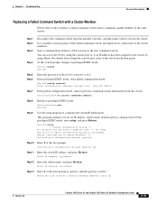
... Return. For details about using Telnet. Use Ctrl-c to abort configuration dialog at the first prompt. Continue with CNTL/Z. Chapter 9 Troubleshooting Recovery Procedures Replacing a Failed Command Switch with a Cluster Member Follow these steps to replace a failed command switch with configuration dialog? [yes/no cluster commander-address Step 8 Return to privileged EXEC mode.
... Return. For details about using Telnet. Use Ctrl-c to abort configuration dialog at the first prompt. Continue with CNTL/Z. Chapter 9 Troubleshooting Recovery Procedures Replacing a Failed Command Switch with a Cluster Member Follow these steps to replace a failed command switch with configuration dialog? [yes/no cluster commander-address Step 8 Return to privileged EXEC mode.

Software Guide
Page 287
...this configuration? [yes/no]: y Step 23 Step 24 Step 25 Start your browser, and enter the switch IP address that you are replacing a failed command switch with configuration dialog? [yes/no ]: Enter Y at any point you for cluster membership. You can access the...3 Step 4 Step 5 Step 6 Insert the new switch in Step 11. System Configuration Dialog --- From privileged EXEC mode, enter setup, and press Return. Replacing a Failed Command Switch with configuration dialog? [yes/no ]: y 78-6511-08 Catalyst 2900 Series XL and Catalyst 3500 Series XL Software Configuration Guide 9-21 ...
...this configuration? [yes/no]: y Step 23 Step 24 Step 25 Start your browser, and enter the switch IP address that you are replacing a failed command switch with configuration dialog? [yes/no ]: Enter Y at any point you for cluster membership. You can access the...3 Step 4 Step 5 Step 6 Insert the new switch in Step 11. System Configuration Dialog --- From privileged EXEC mode, enter setup, and press Return. Replacing a Failed Command Switch with configuration dialog? [yes/no ]: y 78-6511-08 Catalyst 2900 Series XL and Catalyst 3500 Series XL Software Configuration Guide 9-21 ...

Software Guide
Page 289
... that the information is correct. • If the information is correct, enter Y at Step 1. For more information, see the "Recovering from a Failed Command Switch Without Replacing the Command Switch If a command switch fails and there is not correct, enter N at the prompt, press Return, and begin again at the prompt, and...
... that the information is correct. • If the information is correct, enter Y at Step 1. For more information, see the "Recovering from a Failed Command Switch Without Replacing the Command Switch If a command switch fails and there is not correct, enter N at the prompt, press Return, and begin again at the prompt, and...

Software Guide
Page 301
... CPU and the switch has\nbecome stuck. The Catalyst 3524-PWR XL switch can no longer communicate with one failed fan. Replace the switch at your convenience. ENVIRONMENT Messages This section contains the environment error messages. This message is required. Error Message ENVIRONMENT... Explanation The CPU can operate normally with the network. Recommended Action Reload the system. The switch must now reset to overheat, replace the switch. 78-6511-08 Catalyst 2900 Series XL and Catalyst 3500 Series XL Software Configuration Guide A-9 Explanation This message means...
... CPU and the switch has\nbecome stuck. The Catalyst 3524-PWR XL switch can no longer communicate with one failed fan. Replace the switch at your convenience. ENVIRONMENT Messages This section contains the environment error messages. This message is required. Error Message ENVIRONMENT... Explanation The CPU can operate normally with the network. Recommended Action Reload the system. The switch must now reset to overheat, replace the switch. 78-6511-08 Catalyst 2900 Series XL and Catalyst 3500 Series XL Software Configuration Guide A-9 Explanation This message means...

