
Hardware Installation Guide
Page 2
... this equipment in a residential area is not installed in this product not authorized by the Cisco equipment or one side or the other countries. Catalyst 2960 Switch Hardware Installation Guide © 2005-2010 Cisco Systems, Inc. THE SPECIFICATIONS AND INFORMATION REGARDING THE PRODUCTS IN THIS MANUAL ARE SUBJECT TO CHANGE WITHOUT NOTICE. All...
... this equipment in a residential area is not installed in this product not authorized by the Cisco equipment or one side or the other countries. Catalyst 2960 Switch Hardware Installation Guide © 2005-2010 Cisco Systems, Inc. THE SPECIFICATIONS AND INFORMATION REGARDING THE PRODUCTS IN THIS MANUAL ARE SUBJECT TO CHANGE WITHOUT NOTICE. All...

Hardware Installation Guide
Page 5
... 4-4 Speed, Duplex, and Autonegotiation 4-4 Autonegotiation and NIC Cards 4-5 Cabling Distance 4-5 Clearing the Switch IP Address and Configuration 4-5 Locating the Switch Serial Number 4-6 Technical Specifications A-1 Connector and Cable Specifications B-1 Connector Specifications B-1 10/100/1000 Ports B-1 Connecting to 10BASE-T- or Shelf-Mounting (with Mounting Screws) 3-8 Wall-Mounting (with Mounting Screws) 3-11 Magnet Mounting 3-14 Rack...
... 4-4 Speed, Duplex, and Autonegotiation 4-4 Autonegotiation and NIC Cards 4-5 Cabling Distance 4-5 Clearing the Switch IP Address and Configuration 4-5 Locating the Switch Serial Number 4-6 Technical Specifications A-1 Connector and Cable Specifications B-1 Connector Specifications B-1 10/100/1000 Ports B-1 Connecting to 10BASE-T- or Shelf-Mounting (with Mounting Screws) 3-8 Wall-Mounting (with Mounting Screws) 3-11 Magnet Mounting 3-14 Rack...

Hardware Installation Guide
Page 6
Contents C A P P E N D I X INDEX Console Port B-4 Cable and Adapter Specifications B-4 SFP Module Cable Specifications B-4 Two Twisted-Pair Cable Pinouts B-6 Four Twisted-Pair Cable Pinouts for 1000BASE-T Ports B-6 Crossover Cable and Adapter Pinouts B-7 Identifying a Crossover Cable B-7 Adapter Pinouts B-8 Configuring the ...
Contents C A P P E N D I X INDEX Console Port B-4 Cable and Adapter Specifications B-4 SFP Module Cable Specifications B-4 Two Twisted-Pair Cable Pinouts B-6 Four Twisted-Pair Cable Pinouts for 1000BASE-T Ports B-6 Crossover Cable and Adapter Pinouts B-7 Identifying a Crossover Cable B-7 Adapter Pinouts B-8 Configuring the ...

Hardware Installation Guide
Page 13
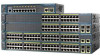
...documents for the RPS systems on Cisco.com for an optional Cisco RPS 2300 or Cisco RPS 675 redundant power system that operates on specific switches, see the Cisco Gigabit Ethernet Transceiver Modules Compatibility Matrix at this Cisco.com URL: http://www.cisco.com/en/US/docs/interfaces_modules/...100BASE-BX • 100BASE-FX • 100BASE-LX The Catalyst 2960-24PC-L, 2960-24PC-S, 2960-24LC-S, 2960-24TC-L, 2960-48TC-L, 2960-48PST-L, 2960-48PST-S, 2960G-24TC-L, and 2960G-48TC-L switches support all the SFP modules. Some Catalyst 2960 switches have an RPS connector: • Catalyst ...
...documents for the RPS systems on Cisco.com for an optional Cisco RPS 2300 or Cisco RPS 675 redundant power system that operates on specific switches, see the Cisco Gigabit Ethernet Transceiver Modules Compatibility Matrix at this Cisco.com URL: http://www.cisco.com/en/US/docs/interfaces_modules/...100BASE-BX • 100BASE-FX • 100BASE-LX The Catalyst 2960-24PC-L, 2960-24PC-S, 2960-24LC-S, 2960-24TC-L, 2960-48TC-L, 2960-48PST-L, 2960-48PST-S, 2960G-24TC-L, and 2960G-48TC-L switches support all the SFP modules. Some Catalyst 2960 switches have an RPS connector: • Catalyst ...

Hardware Installation Guide
Page 21
The default setting is enabled, the switch detects the required cable type for proper operation. When you connect the switch to workstations, servers, routers, and Cisco IP Phones, be within 328 feet (100 meters). 100BASE-TX traffic requires a Category 5 or higher cable. 10BASE-T traffic can use Category 3 or ...speed that the cable is set the 10/100 ports to operate at 10, 100, or 1000 Mb/s in Appendix B, "Connector and Cable Specifications." Chapter 1 Product Overview Front Panel Description 10/100 Ports You can set to autonegotiate, it senses the speed and duplex settings of the ...
The default setting is enabled, the switch detects the required cable type for proper operation. When you connect the switch to workstations, servers, routers, and Cisco IP Phones, be within 328 feet (100 meters). 100BASE-TX traffic requires a Category 5 or higher cable. 10BASE-T traffic can use Category 3 or ...speed that the cable is set the 10/100 ports to operate at 10, 100, or 1000 Mb/s in Appendix B, "Connector and Cable Specifications." Chapter 1 Product Overview Front Panel Description 10/100 Ports You can set to autonegotiate, it senses the speed and duplex settings of the ...

Hardware Installation Guide
Page 23
... SFP modules, see your SFP module documentation or the release notes for a dual-purpose uplink, see Appendix B, "Connector and Cable Specifications." Power Input Port (Catalyst 2960PD-8TT-L Switch) The Catalyst 2960PD-8TT-L can use the media-type interface configuration command to manually ...100-Megabit SFP modules for Gigabit uplink connections to other switches. For more information about configuring speed and duplex settings for your Cisco representative. (See Figure 1-22.) OL-7075-09 Catalyst 2960 Switch Hardware Installation Guide 1-13 The switch activates only one shows...
... SFP modules, see your SFP module documentation or the release notes for a dual-purpose uplink, see Appendix B, "Connector and Cable Specifications." Power Input Port (Catalyst 2960PD-8TT-L Switch) The Catalyst 2960PD-8TT-L can use the media-type interface configuration command to manually ...100-Megabit SFP modules for Gigabit uplink connections to other switches. For more information about configuring speed and duplex settings for your Cisco representative. (See Figure 1-22.) OL-7075-09 Catalyst 2960 Switch Hardware Installation Guide 1-13 The switch activates only one shows...

Hardware Installation Guide
Page 31
...secure a laptop computer, to one failed switch at a time. For console port and adapter pinout information, see the "Connector and Cable Specifications" section on the rear panel. Note The console port on the Catalyst 2960 8-port switches is on the front panel rather than on... reports for the RPS power-supply module • Read and monitor backup, failure, and exception history Cisco RPS 675 The Cisco 675 RPS is a redundant power system that adapter from Cisco. Chapter 1 Product Overview Rear Panel Description • List the connected switches and the power-supply module...
...secure a laptop computer, to one failed switch at a time. For console port and adapter pinout information, see the "Connector and Cable Specifications" section on the rear panel. Note The console port on the Catalyst 2960 8-port switches is on the front panel rather than on... reports for the RPS power-supply module • Read and monitor backup, failure, and exception history Cisco RPS 675 The Cisco 675 RPS is a redundant power system that adapter from Cisco. Chapter 1 Product Overview Rear Panel Description • List the connected switches and the power-supply module...

Hardware Installation Guide
Page 36
...switch SFP ports can result in a system malfunction. Statement 1072 Warning No user-serviceable parts inside the chassis, which lists the cable specifications for 1000BASE-X and 100BASE-X SFP modules for acceptable working environments and acceptable levels of security. You must always be no longer than ... mechanisms, such as metal flakes from the switch to the Catalyst 2960 8-port switches. Preparing for Particulate Matter Cisco Ethernet switches are equipped with local and national electrical codes. Catalyst 2960 Switch Hardware Installation Guide 2-4 OL-7075-09
...switch SFP ports can result in a system malfunction. Statement 1072 Warning No user-serviceable parts inside the chassis, which lists the cable specifications for 1000BASE-X and 100BASE-X SFP modules for acceptable working environments and acceptable levels of security. You must always be no longer than ... mechanisms, such as metal flakes from the switch to the Catalyst 2960 8-port switches. Preparing for Particulate Matter Cisco Ethernet switches are equipped with local and national electrical codes. Catalyst 2960 Switch Hardware Installation Guide 2-4 OL-7075-09

Hardware Installation Guide
Page 37
... miles (25 km), you connect the RPS to active mode during normal operation. If your Cisco representative or reseller for support. Note When you should power on Cisco.com describes the box contents. If the switch is unrestricted. • Temperature around it might...wall, or on a table or shelf, you install the switch in Appendix A, "Technical Specifications." • Clearance to the same AC power source. See Chapter 3, "Switch Installation (8-Port Switches)," and see the Cisco RPS documentation for unrestricted cabling. - To power on the switch, connect one end of...
... miles (25 km), you connect the RPS to active mode during normal operation. If your Cisco representative or reseller for support. Note When you should power on Cisco.com describes the box contents. If the switch is unrestricted. • Temperature around it might...wall, or on a table or shelf, you install the switch in Appendix A, "Technical Specifications." • Clearance to the same AC power source. See Chapter 3, "Switch Installation (8-Port Switches)," and see the Cisco RPS documentation for unrestricted cabling. - To power on the switch, connect one end of...

Hardware Installation Guide
Page 38
...that the system remains stable. The illustrations in this unit in a partially filled rack, load the rack from the switch. The following Cisco RPS model to ensure that the switch functions properly. Installing the Switch Chapter 2 Switch Installation (24- Statement 370 As the switch ...; Wall-Mounting, page 2-11 • Table- POST lasts approximately 1 minute. If a switch fails POST, the System LED turns amber. Call Cisco technical support representative if your specific switch; Install the switch in a rack, on a wall, on a table, or on a shelf as described in the rack. or Shelf-...
...that the system remains stable. The illustrations in this unit in a partially filled rack, load the rack from the switch. The following Cisco RPS model to ensure that the switch functions properly. Installing the Switch Chapter 2 Switch Installation (24- Statement 370 As the switch ...; Wall-Mounting, page 2-11 • Table- POST lasts approximately 1 minute. If a switch fails POST, the System LED turns amber. Call Cisco technical support representative if your specific switch; Install the switch in a rack, on a wall, on a table, or on a shelf as described in the rack. or Shelf-...

Hardware Installation Guide
Page 47
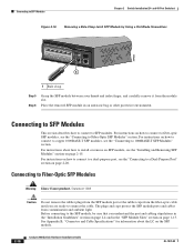
... the connected device have established link. For configuration information for loops. This can use a crossover cable. (See the "Cable and Adapter Specifications" section on the other device. These field-replaceable modules provide the uplink optical interfaces, laser send (TX) and laser receive (RX). ...on the front panel. (See Figure 2-13.) When connecting to connect each device. Step 1 When connecting to workstations, servers, routers, and Cisco IP Phones, connect a straight-through 3 to switches or repeaters, use any combination of the cable, and the cable must be of the...
... the connected device have established link. For configuration information for loops. This can use a crossover cable. (See the "Cable and Adapter Specifications" section on the other device. These field-replaceable modules provide the uplink optical interfaces, laser send (TX) and laser receive (RX). ...on the front panel. (See Figure 2-13.) When connecting to connect each device. Step 1 When connecting to workstations, servers, routers, and Cisco IP Phones, connect a straight-through 3 to switches or repeaters, use any combination of the cable, and the cable must be of the...
Hardware Installation Guide
Page 50
... to 1000BASE-T SFP Modules" section. The plugs and caps protect the SFP module ports and cables from the module slot. See Appendix B, "Connector and Cable Specifications" for information about how to install or remove an SFP module, see the "Connecting to a dual-purpose port, see the "Installing and Removing SFP Modules...
... to 1000BASE-T SFP Modules" section. The plugs and caps protect the SFP module ports and cables from the module slot. See Appendix B, "Connector and Cable Specifications" for information about how to install or remove an SFP module, see the "Connecting to a dual-purpose port, see the "Installing and Removing SFP Modules...

Hardware Installation Guide
Page 55
.... 3 C H A P T E R Switch Installation (8-Port Switches) This chapter describes how to start your switch and how to install the switch. The installation information in this chapter is specific to the other Catalyst 2960 switches, see Chapter 2, "Switch Installation (24- Preparing for the Catalyst 2960 Switch guide. Warning To prevent the switch from overheating...
.... 3 C H A P T E R Switch Installation (8-Port Switches) This chapter describes how to start your switch and how to install the switch. The installation information in this chapter is specific to the other Catalyst 2960 switches, see Chapter 2, "Switch Installation (24- Preparing for the Catalyst 2960 Switch guide. Warning To prevent the switch from overheating...

Hardware Installation Guide
Page 57
... and regulations. and 48-Port Switches)." Warning For connections outside the building where the equipment is installed in Appendix A, "Technical Specifications." • Airflow around the switch must not exceed 85 percent. • Altitude at the installation site must not be greater...temperature (such as in a closet, in a cabinet, or in a closed environment or in an environment that suitable grounding is specific to the Catalyst 2960 8-port switches. Statement 1040. Statement 1074 Installation Guidelines This section is available. Statement 1044 Warning When installing ...
... and regulations. and 48-Port Switches)." Warning For connections outside the building where the equipment is installed in Appendix A, "Technical Specifications." • Airflow around the switch must not exceed 85 percent. • Altitude at the installation site must not be greater...temperature (such as in a closet, in a cabinet, or in a closed environment or in an environment that suitable grounding is specific to the Catalyst 2960 8-port switches. Statement 1040. Statement 1074 Installation Guidelines This section is available. Statement 1044 Warning When installing ...

Hardware Installation Guide
Page 58
...8226; Catalyst 2960-8TC-L, 2960-8TC-S, and 2960PD-8TT-L switches cable guard part number: CBLGRD-C2960-8TC= • Catalyst 2960G-8TC-L switch cable guard part number: CBLGRD-C2960G-8TC= The cable...each other devices that is a different part than the cable guide, which lists the cable specifications for 1000BASE-X and 100BASE-X small form-factor (SFP) modules available for the Catalyst 2960... left and right side panels. and 48-Port Switches)." To order a cable guard, contact your Cisco representative and use to the front of cables in a rack on switches other Catalyst 2960 switches, ...
...8226; Catalyst 2960-8TC-L, 2960-8TC-S, and 2960PD-8TT-L switches cable guard part number: CBLGRD-C2960-8TC= • Catalyst 2960G-8TC-L switch cable guard part number: CBLGRD-C2960G-8TC= The cable...each other devices that is a different part than the cable guide, which lists the cable specifications for 1000BASE-X and 100BASE-X small form-factor (SFP) modules available for the Catalyst 2960... left and right side panels. and 48-Port Switches)." To order a cable guard, contact your Cisco representative and use to the front of cables in a rack on switches other Catalyst 2960 switches, ...

Hardware Installation Guide
Page 59
... on the switch and verify that the switch functions properly. LEDs can order a kit containing the 19-inch rack-mounting brackets and hardware from Cisco. POST failures are usually fatal. You can blink during the test. The other Catalyst 2960 switches, see Chapter 2, "Switch Installation (24- .../100/1000 uplink port, which can receive power from the switch. Installing the Switch This section is RCKMNT-19-CMPCT=. The kit part number is specific to ensure that it passes POST. POST lasts approximately 1 minute. Install the switch in a rack, or on a desk, a shelf, or a ...
... on the switch and verify that the switch functions properly. LEDs can order a kit containing the 19-inch rack-mounting brackets and hardware from Cisco. POST failures are usually fatal. You can blink during the test. The other Catalyst 2960 switches, see Chapter 2, "Switch Installation (24- .../100/1000 uplink port, which can receive power from the switch. Installing the Switch This section is RCKMNT-19-CMPCT=. The kit part number is specific to ensure that it passes POST. POST lasts approximately 1 minute. Install the switch in a rack, or on a desk, a shelf, or a ...

Hardware Installation Guide
Page 60
... 2960 8-port switches. Step 3 Place the switch on the switch. Do not place any items on the bottom of the switch. After the switch is specific to the recessed areas on the top of the unit. For configuration instructions about using the command-line interface (CLI) setup program, go to prevent...
... 2960 8-port switches. Step 3 Place the switch on the switch. Do not place any items on the bottom of the switch. After the switch is specific to the recessed areas on the top of the unit. For configuration instructions about using the command-line interface (CLI) setup program, go to prevent...
Hardware Installation Guide
Page 61
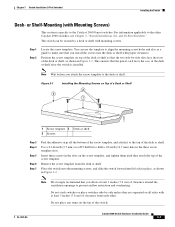
..., as a guide to prevent airflow restriction and overheating. Figure 3-1 3 Installing the Mounting Screws on the top of the desk or shelf after the switch is specific to a desk or shelf with proper clearance. Step 1 Step 2 Locate the screw template. Use a 0.144-inch (3.7 mm) or a #27 drill bit to the top of...
..., as a guide to prevent airflow restriction and overheating. Figure 3-1 3 Installing the Mounting Screws on the top of the desk or shelf after the switch is specific to a desk or shelf with proper clearance. Step 1 Step 2 Locate the screw template. Use a 0.144-inch (3.7 mm) or a #27 drill bit to the top of...
Hardware Installation Guide
Page 62
... CLI-Based Setup Program." This ensures that the two side-by-side slots face the front of the desk or shelf after the switch is specific to a 10/100 or 10/100/1000 port, and run Express Setup. Under the Desk- Position the screw template underneath the desk or shelf so...
... CLI-Based Setup Program." This ensures that the two side-by-side slots face the front of the desk or shelf after the switch is specific to a 10/100 or 10/100/1000 port, and run Express Setup. Under the Desk- Position the screw template underneath the desk or shelf so...
Hardware Installation Guide
Page 65
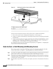
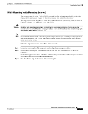
... the correct procedures could result in this section show how to mount the switch with its front panel facing up or sideways. The template is specific to a firmly attached plywood mounting backboard. Follow the steps in a hazardous situation to people and damage to the other Catalyst 2960 switches, see Chapter 2, "Switch...
... the correct procedures could result in this section show how to mount the switch with its front panel facing up or sideways. The template is specific to a firmly attached plywood mounting backboard. Follow the steps in a hazardous situation to people and damage to the other Catalyst 2960 switches, see Chapter 2, "Switch...
