
Hardware Installation Guide
Page 23
...2960-48TT-S The transceiver modules are not redundant interfaces. For more information about these sources: 1. For more information about cabling requirements, see Appendix B, "Connector and Cable Specifications." For information about configuring speed and duplex settings for Gigabit uplink connections to a ... order it from these SFP modules, see the software configuration guide. This external power adapter (PWR-A=) is on the active connector. You can receive power from your Cisco representative. (See Figure 1-22.) OL-7075-09 Catalyst 2960 Switch Hardware Installation ...
...2960-48TT-S The transceiver modules are not redundant interfaces. For more information about these sources: 1. For more information about cabling requirements, see Appendix B, "Connector and Cable Specifications." For information about configuring speed and duplex settings for Gigabit uplink connections to a ... order it from these SFP modules, see the software configuration guide. This external power adapter (PWR-A=) is on the active connector. You can receive power from your Cisco representative. (See Figure 1-22.) OL-7075-09 Catalyst 2960 Switch Hardware Installation ...

Hardware Installation Guide
Page 26
... in standby mode or in a switch has failed, and the RPS is providing power to another device (redundancy has been allocated to provide back-up power, if required. Contact Cisco Systems. The internal power supply in a fault condition. DUPLX SPEED1 PoE2 Port duplex mode Port speed PoE port... power The port duplex mode: full duplex or half duplex. When installed in Catalyst 2960 ...
... in standby mode or in a switch has failed, and the RPS is providing power to another device (redundancy has been allocated to provide back-up power, if required. Contact Cisco Systems. The internal power supply in a fault condition. DUPLX SPEED1 PoE2 Port duplex mode Port speed PoE port... power The port duplex mode: full duplex or half duplex. When installed in Catalyst 2960 ...

Hardware Installation Guide
Page 36
... tool, lock and key or other particles, causing contaminant buildup inside . However, these requirements: • For 10/100/1000 ports, cable lengths from construction activities). Installation Guidelines This...lists the cable specifications for 1000BASE-X and 100BASE-X SFP modules for Particulate Matter Cisco Ethernet switches are made using such interconnection methods, unless the exposed metal parts... feet (100 meters). • The cables meet the specifications in Table B-1 on Power over Ethernet (PoE) circuits if interconnections are made aware of suspended particulate matter: &#...
... tool, lock and key or other particles, causing contaminant buildup inside . However, these requirements: • For 10/100/1000 ports, cable lengths from construction activities). Installation Guidelines This...lists the cable specifications for 1000BASE-X and 100BASE-X SFP modules for Particulate Matter Cisco Ethernet switches are made using such interconnection methods, unless the exposed metal parts... feet (100 meters). • The cables meet the specifications in Table B-1 on Power over Ethernet (PoE) circuits if interconnections are made aware of suspended particulate matter: &#...

Hardware Installation Guide
Page 59
... turn green. Verifying Switch Operation Before installing the switch in a 19-inch rack requires an optional bracket kit that is missing or damaged, contact your switch fails POST. As the switch powers on, it passes POST. LEDs can order a kit containing the 19-inch rack...to supply a number-2 Phillips screwdriver to rack-mount the switch. You can order a kit (part number ACS-DSBUASYN=) with that adapter from Cisco. This section describes these installation procedures: • Desk- You can also connect the switch to -DB-25 female DTE adapter. Tools and ...
... turn green. Verifying Switch Operation Before installing the switch in a 19-inch rack requires an optional bracket kit that is missing or damaged, contact your switch fails POST. As the switch powers on, it passes POST. LEDs can order a kit containing the 19-inch rack...to supply a number-2 Phillips screwdriver to rack-mount the switch. You can order a kit (part number ACS-DSBUASYN=) with that adapter from Cisco. This section describes these installation procedures: • Desk- You can also connect the switch to -DB-25 female DTE adapter. Tools and ...
Hardware Installation Guide
Page 70
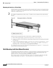
..."Switch Installation (24- This section is RCKMNT-19-CMPCT=. and 48-Port Switches)." 3-16 Catalyst 2960 Switch Hardware Installation Guide OL-7075-09 Power on page 3-5. 2. Installing the Switch Chapter 3 Switch Installation (8-Port Switches) Mounting the Switch in a 19-Inch Rack After the brackets are... go to Appendix C, "Configuring the Switch with Rack-Mount Brackets) To install the Catalyst 2960 8-port switches in a 19-inch rack requires an optional bracket kit that you allow at least 1.75 inches (4 cm) of clearance above each switch in the rack. You can order...
..."Switch Installation (24- This section is RCKMNT-19-CMPCT=. and 48-Port Switches)." 3-16 Catalyst 2960 Switch Hardware Installation Guide OL-7075-09 Power on page 3-5. 2. Installing the Switch Chapter 3 Switch Installation (8-Port Switches) Mounting the Switch in a 19-Inch Rack After the brackets are... go to Appendix C, "Configuring the Switch with Rack-Mount Brackets) To install the Catalyst 2960 8-port switches in a 19-inch rack requires an optional bracket kit that you allow at least 1.75 inches (4 cm) of clearance above each switch in the rack. You can order...

Hardware Installation Guide
Page 75
... use the same type of encoding, optical frequency, and fiber type. This encoding provides a way for Cisco to identify and validate that the module meets the requirements for loose connections. OL-7075-09 Catalyst 2960 Switch Hardware Installation Guide 4-3 Chapter 4 Troubleshooting Diagnosing Problems Ethernet...8226; Make sure that causes it to the correct ports. • Verify that is not. Link Status Verify that both devices have power. • Verify that you have encountered physical stress that both ends of supported SFP modules. • Use the show link, but ...
... use the same type of encoding, optical frequency, and fiber type. This encoding provides a way for Cisco to identify and validate that the module meets the requirements for loose connections. OL-7075-09 Catalyst 2960 Switch Hardware Installation Guide 4-3 Chapter 4 Troubleshooting Diagnosing Problems Ethernet...8226; Make sure that causes it to the correct ports. • Verify that is not. Link Status Verify that both devices have power. • Verify that you have encountered physical stress that both ends of supported SFP modules. • Use the show link, but ...
Hardware Installation Guide
Page 82
... Guide A-2 OL-7075-09 Appendix A Technical Specifications Table A-2 Catalyst 2960-24-S, 2960-24TC-S, and 2960-48TC-S Switch Specifications Power Requirements AC input voltage Power consumption Power rating Physical Dimensions Weight Dimensions (H x D x W) 100 to 240 VAC (autoranging) 1.3 to 0.8 A, 50 to 60...9.3 x 17.5 in. (4.39 x 23.62 x 44.45 cm) Table A-3 Catalyst 2960-24PC-L, Catalyst 2960-24LT-L, and Catalyst 2960-48PST-L Switch Specifications Power Requirements AC input voltage 100 to 240 VAC (autoranging) 8 to 4 A, 50 to 60 Hz (Catalyst 2960-24PC-L) 3 to 1.5 A, 50 ...
... Guide A-2 OL-7075-09 Appendix A Technical Specifications Table A-2 Catalyst 2960-24-S, 2960-24TC-S, and 2960-48TC-S Switch Specifications Power Requirements AC input voltage Power consumption Power rating Physical Dimensions Weight Dimensions (H x D x W) 100 to 240 VAC (autoranging) 1.3 to 0.8 A, 50 to 60...9.3 x 17.5 in. (4.39 x 23.62 x 44.45 cm) Table A-3 Catalyst 2960-24PC-L, Catalyst 2960-24LT-L, and Catalyst 2960-48PST-L Switch Specifications Power Requirements AC input voltage 100 to 240 VAC (autoranging) 8 to 4 A, 50 to 60 Hz (Catalyst 2960-24PC-L) 3 to 1.5 A, 50 ...

Hardware Installation Guide
Page 83
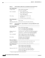
...44.45 cm) Table A-5 Catalyst 2960-48TC-L, 2960-48TT-S, and 2960-48TT-L Switch Specifications Power Requirements AC input voltage DC input voltage for RPS 2300 DC input voltage for RPS 675 Power consumption Power rating Physical Dimensions Weight Dimensions (H x D x W) 100 to 240 VAC (autoranging) ... 44.45 cm) Table A-6 Catalyst 2960G-24TC-L and Catalyst 2960G-48TC-L Switch Specifications Power Requirements AC input voltage DC input voltage for RPS 2300 DC input voltage for RPS 675 Power consumption Power rating Physical Dimensions Weight Dimensions (H x D x W) 100 to 240 VAC (autoranging...
...44.45 cm) Table A-5 Catalyst 2960-48TC-L, 2960-48TT-S, and 2960-48TT-L Switch Specifications Power Requirements AC input voltage DC input voltage for RPS 2300 DC input voltage for RPS 675 Power consumption Power rating Physical Dimensions Weight Dimensions (H x D x W) 100 to 240 VAC (autoranging) ... 44.45 cm) Table A-6 Catalyst 2960G-24TC-L and Catalyst 2960G-48TC-L Switch Specifications Power Requirements AC input voltage DC input voltage for RPS 2300 DC input voltage for RPS 675 Power consumption Power rating Physical Dimensions Weight Dimensions (H x D x W) 100 to 240 VAC (autoranging...

Hardware Installation Guide
Page 84
...Catalyst 2960PD-8TT-L switch is for the switch system and does not refer to 60 Hz (Catalyst 2960G-8TC-L) Unspecified when AC power adapter installed (Catalyst 2960PD-8TT-L) 48 VDC, 0.3 A (Catalyst 2960PD-8TT-L) 20 W, 68 BTUs per hour (Catalyst 2960-8TC...Catalyst 2960G-8TC-L) 1. Appendix A Technical Specifications Table A-7 Catalyst 2960-8TC-L, 2960G-8TC-L, 2960-8TC-S, and 2960PD-8TT-L Switch Specifications Power Requirements AC input voltage DC input voltage Power consumption Power rating 100 to 240 VAC (autoranging) 0.5 to 0.25 A, 50 to 60 Hz (Catalyst 2960-8TC-L and Catalyst 2960-8TC-S)...
...Catalyst 2960PD-8TT-L switch is for the switch system and does not refer to 60 Hz (Catalyst 2960G-8TC-L) Unspecified when AC power adapter installed (Catalyst 2960PD-8TT-L) 48 VDC, 0.3 A (Catalyst 2960PD-8TT-L) 20 W, 68 BTUs per hour (Catalyst 2960-8TC...Catalyst 2960G-8TC-L) 1. Appendix A Technical Specifications Table A-7 Catalyst 2960-8TC-L, 2960G-8TC-L, 2960-8TC-S, and 2960PD-8TT-L Switch Specifications Power Requirements AC input voltage DC input voltage Power consumption Power rating 100 to 240 VAC (autoranging) 0.5 to 0.25 A, 50 to 60 Hz (Catalyst 2960-8TC-L and Catalyst 2960-8TC-S)...
Hardware Installation Guide
Page 85
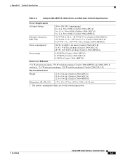
... (Catalyst 2960-24LC-S) 0.5 KVA (Catalyst 2960-48PST-S) Power over Ethernet 15.4 W-per-port maximum, 370-W switch maximum (Catalyst 2960-48PST-S and 2960-24PC-S switches). 15.4 W-per-port maximum, 124-W switch maximum (Catalyst 2960-24LC-S). Appendix A Technical Specifications Table A-8 Catalyst 2960-48PST-S, 2960-24PC-S, and 2960-24LC-S Switch Specifications Power Requirements AC input voltage DC input voltage...
... (Catalyst 2960-24LC-S) 0.5 KVA (Catalyst 2960-48PST-S) Power over Ethernet 15.4 W-per-port maximum, 370-W switch maximum (Catalyst 2960-48PST-S and 2960-24PC-S switches). 15.4 W-per-port maximum, 124-W switch maximum (Catalyst 2960-24LC-S). Appendix A Technical Specifications Table A-8 Catalyst 2960-48PST-S, 2960-24PC-S, and 2960-24LC-S Switch Specifications Power Requirements AC input voltage DC input voltage...

Hardware Installation Guide
Page 98
...the setup program, which runs automatically after the switch is also required if you are usually fatal. You must assign an IP address and other LEDs remain solid green. As the switch powers on, it begins the power-on self test (POST), a series of tests that runs ...switch operating status. When the POST completes successfully, the System LED remains green. POST failures are connecting the switch to a Cisco redundant power system (RPS), refer to the documentation that the switch functions properly. Entering the Initial Configuration Information To set up . This information is...
...the setup program, which runs automatically after the switch is also required if you are usually fatal. You must assign an IP address and other LEDs remain solid green. As the switch powers on, it begins the power-on self test (POST), a series of tests that runs ...switch operating status. When the POST completes successfully, the System LED remains green. POST failures are connecting the switch to a Cisco redundant power system (RPS), refer to the documentation that the switch functions properly. Entering the Initial Configuration Information To set up . This information is...

Hardware Installation Guide
Page 105
... A-1 I installation assigning the IP address C-4 connecting to a power source C-4 mounting in a rack (8-port switches) 3-15 to 3-16 on desk or shelf 2-14, 3-6, 3-11 under a desk 3-8 using a magnet 3-14 site requirements 2-4, 3-3 starting the terminal emulation software C-3 See also procedures ...installation instructions warning 2-2, 3-2 installing SFP modules 2-16 to 2-17 internal power supply 1-20 J jewelry removal warning 2-2, 3-2 L LEDs OL-7075-...
... A-1 I installation assigning the IP address C-4 connecting to a power source C-4 mounting in a rack (8-port switches) 3-15 to 3-16 on desk or shelf 2-14, 3-6, 3-11 under a desk 3-8 using a magnet 3-14 site requirements 2-4, 3-3 starting the terminal emulation software C-3 See also procedures ...installation instructions warning 2-2, 3-2 installing SFP modules 2-16 to 2-17 internal power supply 1-20 J jewelry removal warning 2-2, 3-2 L LEDs OL-7075-...


