
Hardware Installation Guide
Page 2
... to comply with the specifications in a residential installation. CCDE, CCENT, CCSI, Cisco Eos, Cisco Explorer, Cisco HealthPresence, Cisco IronPort, the Cisco logo, Cisco Nurse Connect, Cisco Pulse, Cisco SensorBase, Cisco StackPower, Cisco StadiumVision, Cisco TelePresence, Cisco TrustSec, Cisco Unified Computing System, Cisco WebEx, DCE, Flip Channels... the product. In that interference will be required to be actual addresses. These specifications are service marks; CISCO AND THE ABOVE-NAMED SUPPLIERS DISCLAIM ALL WARRANTIES, EXPRESSED OR IMPLIED, INCLUDING, WITHOUT...
... to comply with the specifications in a residential installation. CCDE, CCENT, CCSI, Cisco Eos, Cisco Explorer, Cisco HealthPresence, Cisco IronPort, the Cisco logo, Cisco Nurse Connect, Cisco Pulse, Cisco SensorBase, Cisco StackPower, Cisco StadiumVision, Cisco TelePresence, Cisco TrustSec, Cisco Unified Computing System, Cisco WebEx, DCE, Flip Channels... the product. In that interference will be required to be actual addresses. These specifications are service marks; CISCO AND THE ABOVE-NAMED SUPPLIERS DISCLAIM ALL WARRANTIES, EXPRESSED OR IMPLIED, INCLUDING, WITHOUT...

Hardware Installation Guide
Page 5
... 4-4 Speed, Duplex, and Autonegotiation 4-4 Autonegotiation and NIC Cards 4-5 Cabling Distance 4-5 Clearing the Switch IP Address and Configuration 4-5 Locating the Switch Serial Number 4-6 Technical Specifications A-1 Connector and Cable Specifications B-1 Connector Specifications B-1 10/100/1000 Ports B-1 Connecting to 10BASE-T- Contents 4 C H A P T E R A A P P E N D I X B A P P E N D I X OL-7075-09 Desk- or Shelf-Mounting (with Mounting Screws) 3-8 Wall-Mounting (with Mounting Screws...
... 4-4 Speed, Duplex, and Autonegotiation 4-4 Autonegotiation and NIC Cards 4-5 Cabling Distance 4-5 Clearing the Switch IP Address and Configuration 4-5 Locating the Switch Serial Number 4-6 Technical Specifications A-1 Connector and Cable Specifications B-1 Connector Specifications B-1 10/100/1000 Ports B-1 Connecting to 10BASE-T- Contents 4 C H A P T E R A A P P E N D I X B A P P E N D I X OL-7075-09 Desk- or Shelf-Mounting (with Mounting Screws) 3-8 Wall-Mounting (with Mounting Screws...

Hardware Installation Guide
Page 6
Contents C A P P E N D I X INDEX Console Port B-4 Cable and Adapter Specifications B-4 SFP Module Cable Specifications B-4 Two Twisted-Pair Cable Pinouts B-6 Four Twisted-Pair Cable Pinouts for 1000BASE-T Ports B-6 Crossover Cable and Adapter Pinouts B-7 Identifying a Crossover Cable B-7 Adapter Pinouts B-8 Configuring the ...
Contents C A P P E N D I X INDEX Console Port B-4 Cable and Adapter Specifications B-4 SFP Module Cable Specifications B-4 Two Twisted-Pair Cable Pinouts B-6 Four Twisted-Pair Cable Pinouts for 1000BASE-T Ports B-6 Crossover Cable and Adapter Pinouts B-7 Identifying a Crossover Cable B-7 Adapter Pinouts B-8 Configuring the ...

Hardware Installation Guide
Page 13
...half-duplex mode. See the compatibility matrix documents for the RPS systems on specific switches, see the Cisco Gigabit Ethernet Transceiver Modules Compatibility Matrix at this Cisco.com URL: http://www.cisco.com/en/US/docs/interfaces_modules/transceiver_modules/compatibility/matrix/ OL_6981.html The 1000BASE-T ... Catalyst 2960-24TC-S, and Catalyst 2960-48TC-S switches support only 1000BASE-LX/LH, 1000BASE-SX, and 100BASE-FX SFP modules. For specific information about which SFP modules are the SFP modules supported by the switches: • 1000BASE-CWDM • 1000BASE-BX • 1000BASE...
...half-duplex mode. See the compatibility matrix documents for the RPS systems on specific switches, see the Cisco Gigabit Ethernet Transceiver Modules Compatibility Matrix at this Cisco.com URL: http://www.cisco.com/en/US/docs/interfaces_modules/transceiver_modules/compatibility/matrix/ OL_6981.html The 1000BASE-T ... Catalyst 2960-24TC-S, and Catalyst 2960-48TC-S switches support only 1000BASE-LX/LH, 1000BASE-SX, and 100BASE-FX SFP modules. For specific information about which SFP modules are the SFP modules supported by the switches: • 1000BASE-CWDM • 1000BASE-BX • 1000BASE...

Hardware Installation Guide
Page 21
...automatic medium-dependent interface crossover (auto-MDIX) feature. You can use the mdix auto interface configuration command in Appendix B, "Connector and Cable Specifications." You can also set the 10/100/1000 ports to switches or hubs, use a twisted four-pair, Category 5 or higher cable ...auto-MDIX feature is , the fastest line speed that the cable is a straight-through cable for connections to workstations, servers, routers, and Cisco IP Phones, be within 328 feet (100 meters). 100BASE-TX and 1000BASE-T traffic requires a Category 5 or higher cable. 10BASE-T traffic can...
...automatic medium-dependent interface crossover (auto-MDIX) feature. You can use the mdix auto interface configuration command in Appendix B, "Connector and Cable Specifications." You can also set the 10/100/1000 ports to switches or hubs, use a twisted four-pair, Category 5 or higher cable ...auto-MDIX feature is , the fastest line speed that the cable is a straight-through cable for connections to workstations, servers, routers, and Cisco IP Phones, be within 328 feet (100 meters). 100BASE-TX and 1000BASE-T traffic requires a Category 5 or higher cable. 10BASE-T traffic can...

Hardware Installation Guide
Page 23
...-8TT-L • Catalyst 2960-24LT-L • Catalyst 2960-24-S • Catalyst 2960-24TT-L • Catalyst 2960-48TT-L • Catalyst 2960-48TT-S The transceiver modules are not redundant ... dual-purpose uplink, see your SFP module documentation or the release notes for your Cisco representative. (See Figure 1-22.) OL-7075-09 Catalyst 2960 Switch Hardware Installation Guide... 1-21.) 2. For more information about cabling requirements, see Appendix B, "Connector and Cable Specifications." Through an external AC power adapter that first links up. Dual-Purpose Port You can ...
...-8TT-L • Catalyst 2960-24LT-L • Catalyst 2960-24-S • Catalyst 2960-24TT-L • Catalyst 2960-48TT-L • Catalyst 2960-48TT-S The transceiver modules are not redundant ... dual-purpose uplink, see your SFP module documentation or the release notes for your Cisco representative. (See Figure 1-22.) OL-7075-09 Catalyst 2960 Switch Hardware Installation Guide... 1-21.) 2. For more information about cabling requirements, see Appendix B, "Connector and Cable Specifications." Through an external AC power adapter that first links up. Dual-Purpose Port You can ...

Hardware Installation Guide
Page 31
...can order a kit (part number ACS-DSBUASYN=) containing that supports six network devices and provides power to one failed switch at a time. The Cisco RPS 675 has two output levels: -48 V and 12 V. Note The console port on the left -side panel. Security Slots The Catalyst 2960... Security slot OL-7075-09 Catalyst 2960 Switch Hardware Installation Guide 1-21 For console port and adapter pinout information, see the "Connector and Cable Specifications" section on the rear panel. The total maximum output power is on the front panel rather than on page B-1. Chapter 1 Product Overview Rear...
...can order a kit (part number ACS-DSBUASYN=) containing that supports six network devices and provides power to one failed switch at a time. The Cisco RPS 675 has two output levels: -48 V and 12 V. Note The console port on the left -side panel. Security Slots The Catalyst 2960... Security slot OL-7075-09 Catalyst 2960 Switch Hardware Installation Guide 1-21 For console port and adapter pinout information, see the "Connector and Cable Specifications" section on the rear panel. The total maximum output power is on the front panel rather than on page B-1. Chapter 1 Product Overview Rear...

Hardware Installation Guide
Page 36
...the equipment must comply with cooling mechanisms, such as metal flakes from the switch to all Catalyst 2960 switches except for Particulate Matter Cisco Ethernet switches are made first and disconnected last. However, these fans and blowers can draw dust and other means of suspended particulate matter...installing or replacing the unit, the ground connection must be no longer than 328 feet (100 meters). • The cables meet the specifications in an environment as free as possible from dust and foreign conductive material (such as fans and blowers. Statement 1072 Warning No user...
...the equipment must comply with cooling mechanisms, such as metal flakes from the switch to all Catalyst 2960 switches except for Particulate Matter Cisco Ethernet switches are made first and disconnected last. However, these fans and blowers can draw dust and other means of suspended particulate matter...installing or replacing the unit, the ground connection must be no longer than 328 feet (100 meters). • The cables meet the specifications in an environment as free as possible from dust and foreign conductive material (such as fans and blowers. Statement 1072 Warning No user...

Hardware Installation Guide
Page 37
...temperature. You can easily read the front-panel indicators. - The rear-panel power connector is within the ranges listed in Appendix A, "Technical Specifications." • Clearance to an AC power outlet. Box Contents The switch getting started guide on the 1000BASE-ZX SFP module at each end ... meets these conditions: - If any item is sufficient for unrestricted cabling. - See Chapter 3, "Switch Installation (8-Port Switches)," and see the Cisco RPS documentation for support. To power on the switch, connect one end of the AC power cord to the AC power connector on the switch...
...temperature. You can easily read the front-panel indicators. - The rear-panel power connector is within the ranges listed in Appendix A, "Technical Specifications." • Clearance to an AC power outlet. Box Contents The switch getting started guide on the 1000BASE-ZX SFP module at each end ... meets these conditions: - If any item is sufficient for unrestricted cabling. - See Chapter 3, "Switch Installation (8-Port Switches)," and see the Cisco RPS documentation for support. To power on the switch, connect one end of the AC power cord to the AC power connector on the switch...

Hardware Installation Guide
Page 38
...switch fails POST, the System LED turns amber. Warning To prevent bodily injury when mounting or servicing this section might not show your specific switch; Statement 1006 Catalyst 2960 Switch Hardware Installation Guide 2-6 OL-7075-09 POST failures are provided to those switches, see Chapter 3, ...switches except the Catalyst 8-port switches. The illustrations in a partially filled rack, load the rack from the switch. The following Cisco RPS model to the top with stabilizing devices, install the stabilizers before mounting or servicing the unit in the rack. The ...
...switch fails POST, the System LED turns amber. Warning To prevent bodily injury when mounting or servicing this section might not show your specific switch; Statement 1006 Catalyst 2960 Switch Hardware Installation Guide 2-6 OL-7075-09 POST failures are provided to those switches, see Chapter 3, ...switches except the Catalyst 8-port switches. The illustrations in a partially filled rack, load the rack from the switch. The following Cisco RPS model to the top with stabilizing devices, install the stabilizers before mounting or servicing the unit in the rack. The ...

Hardware Installation Guide
Page 47
...and component handling procedures. If the port LED does not turn on page B-4 for reliable communications. See the "SFP Module Cable Specifications" section on when both the switch and the connected device have established link. Each SFP module must not exceed the stipulated cable length...connect to use any combination of SFP modules that the Catalyst 2960 switch supports. Step 1 When connecting to workstations, servers, routers, and Cisco IP Phones, connect a straight-through 3 to the Catalyst 2960 switch release notes for solutions to 30 seconds, and then the port LED...
...and component handling procedures. If the port LED does not turn on page B-4 for reliable communications. See the "SFP Module Cable Specifications" section on when both the switch and the connected device have established link. Each SFP module must not exceed the stipulated cable length...connect to use any combination of SFP modules that the Catalyst 2960 switch supports. Step 1 When connecting to workstations, servers, routers, and Cisco IP Phones, connect a straight-through 3 to the Catalyst 2960 switch release notes for solutions to 30 seconds, and then the port LED...
Hardware Installation Guide
Page 50
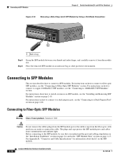
... port, see the "Installing and Removing SFP Modules" section on page 2-15. Connecting to SFP Modules Chapter 2 Switch Installation (24- See Appendix B, "Connector and Cable Specifications" for information about how to SFP modules. Connecting to Fiber-Optic SFP Modules Warning Class 1 laser product. Connecting to SFP Modules This section describes how...
... port, see the "Installing and Removing SFP Modules" section on page 2-15. Connecting to SFP Modules Chapter 2 Switch Installation (24- See Appendix B, "Connector and Cable Specifications" for information about how to SFP modules. Connecting to Fiber-Optic SFP Modules Warning Class 1 laser product. Connecting to SFP Modules This section describes how...

Hardware Installation Guide
Page 55
.... Read the topics and perform the procedures in this order: • Preparing for the Catalyst 2960 Switch guide. The installation information in this chapter is specific to install the switch.
.... Read the topics and perform the procedures in this order: • Preparing for the Catalyst 2960 Switch guide. The installation information in this chapter is specific to install the switch.

Hardware Installation Guide
Page 57
... network termination unit with local and national electrical codes. Never defeat the ground conductor or operate the equipment in Appendix A, "Technical Specifications." • Airflow around the unit does not exceed 113°F (45°C). Statement 1073 Warning Installation of a suitably installed ... the installation site must comply with integral circuit protection: 10/100/1000 Ethernet. Statement 1074 Installation Guidelines This section is specific to observe these requirements: • The operating environment must be within the ranges listed in the absence of the equipment...
... network termination unit with local and national electrical codes. Never defeat the ground conductor or operate the equipment in Appendix A, "Technical Specifications." • Airflow around the unit does not exceed 113°F (45°C). Statement 1073 Warning Installation of a suitably installed ... the installation site must comply with integral circuit protection: 10/100/1000 Ethernet. Statement 1074 Installation Guidelines This section is specific to observe these requirements: • The operating environment must be within the ranges listed in the absence of the equipment...

Hardware Installation Guide
Page 58
...8TC-L and Catalyst 2960G-8TC-L switches. To order a cable guard, contact your Cisco representative and use these conditions - According to manage a large number of cables in a rack on page B-5, which lists the cable specifications for 1000BASE-X and 100BASE-X small form-factor (SFP) modules available for the ... and rear panels meets these part numbers: • Catalyst 2960-8TC-L, 2960-8TC-S, and 2960PD-8TT-L switches cable guard part number: CBLGRD-C2960-8TC= • Catalyst 2960G-8TC-L switch cable guard part number: CBLGRD-C2960G-8TC= The cable guard is less than the cable guide,...
...8TC-L and Catalyst 2960G-8TC-L switches. To order a cable guard, contact your Cisco representative and use these conditions - According to manage a large number of cables in a rack on page B-5, which lists the cable specifications for 1000BASE-X and 100BASE-X small form-factor (SFP) modules available for the ... and rear panels meets these part numbers: • Catalyst 2960-8TC-L, 2960-8TC-S, and 2960PD-8TT-L switches cable guard part number: CBLGRD-C2960-8TC= • Catalyst 2960G-8TC-L switch cable guard part number: CBLGRD-C2960G-8TC= The cable guard is less than the cable guide,...

Hardware Installation Guide
Page 59
..., you should power on the switch, and connect the other LEDs remain solid green. After a successful POST, disconnect the power cord from Cisco. Chapter 3 Switch Installation (8-Port Switches) Verifying Switch Operation Installing the Catalyst 2960 8-port switches in a 19-inch rack requires an optional ... to -DB-25 female DTE adapter. If a switch fails POST, the System LED turns amber. Installing the Switch This section is specific to an AC power adapter on page 3-5. Verifying Switch Operation Before installing the switch in the "Installing the Switch" section on the rear...
..., you should power on the switch, and connect the other LEDs remain solid green. After a successful POST, disconnect the power cord from Cisco. Chapter 3 Switch Installation (8-Port Switches) Verifying Switch Operation Installing the Catalyst 2960 8-port switches in a 19-inch rack requires an optional ... to -DB-25 female DTE adapter. If a switch fails POST, the System LED turns amber. Installing the Switch This section is specific to an AC power adapter on page 3-5. Verifying Switch Operation Before installing the switch in the "Installing the Switch" section on the rear...

Hardware Installation Guide
Page 60
... least 3 inches (7.6 cm) of the switch. Catalyst 2960 Switch Hardware Installation Guide 3-6 OL-7075-09 or Shelf-Mounting (without mounting screws. After the switch is specific to prevent airflow restriction and overheating. Connect to the front-panel ports. or Shelf-Mounting (with Mounting Screws), page 3-8 • Wall-Mounting (with Mounting Screws...
... least 3 inches (7.6 cm) of the switch. Catalyst 2960 Switch Hardware Installation Guide 3-6 OL-7075-09 or Shelf-Mounting (without mounting screws. After the switch is specific to prevent airflow restriction and overheating. Connect to the front-panel ports. or Shelf-Mounting (with Mounting Screws), page 3-8 • Wall-Mounting (with Mounting Screws...
Hardware Installation Guide
Page 61
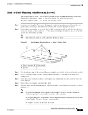
... power cord faces the rear of the switch. Do not place any items on the top of the desk or shelf after the switch is specific to prevent airflow restriction and overheating. OL-7075-09 Catalyst 2960 Switch Hardware Installation Guide 3-7
... power cord faces the rear of the switch. Do not place any items on the top of the desk or shelf after the switch is specific to prevent airflow restriction and overheating. OL-7075-09 Catalyst 2960 Switch Hardware Installation Guide 3-7
Hardware Installation Guide
Page 62
... to the Catalyst 2960 8-port switches. or Shelf-Mounting (with Mounting Screws) This section is also used to align the mounting screw holes and is specific to Appendix C, "Configuring the Switch with proper clearance. and 48-Port Switches)." The template is used as shown in Figure 3-3. Power on page 3-5. 2. See the...
... to the Catalyst 2960 8-port switches. or Shelf-Mounting (with Mounting Screws) This section is also used to align the mounting screw holes and is specific to Appendix C, "Configuring the Switch with proper clearance. and 48-Port Switches)." The template is used as shown in Figure 3-3. Power on page 3-5. 2. See the...
Hardware Installation Guide
Page 65
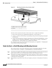
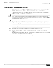
... 3 Switch Installation (8-Port Switches) Installing the Switch Wall-Mounting (with Mounting Screws) This section is used to align the mounting screw holes. The template is specific to a firmly attached plywood mounting backboard.
... 3 Switch Installation (8-Port Switches) Installing the Switch Wall-Mounting (with Mounting Screws) This section is used to align the mounting screw holes. The template is specific to a firmly attached plywood mounting backboard.
