Hardware Installation Guide
Page 74
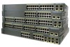
... broken or missing pins on page 1-14 for troubleshooting information about the switch. If POST fails, the system LED remains amber. Contact your Cisco technical support representative if your switch does not pass POST. In these sections when troubleshooting switch connectivity problems: • Bad or Damaged Cable,... the system LED slowly blinks green. When POST completes, the system LED blinks amber. Monitor Switch LEDs Look at the physical layer but then cause packet corruption because of tests that runs automatically to see if the problem also exists there. You can identify this...
... broken or missing pins on page 1-14 for troubleshooting information about the switch. If POST fails, the system LED remains amber. Contact your Cisco technical support representative if your switch does not pass POST. In these sections when troubleshooting switch connectivity problems: • Bad or Damaged Cable,... the system LED slowly blinks green. When POST completes, the system LED blinks amber. Monitor Switch LEDs Look at the physical layer but then cause packet corruption because of tests that runs automatically to see if the problem also exists there. You can identify this...
Software Guide
Page 43
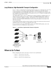
... 74089 8 Gbps CWDM OADM modules Eight 1-Gbps connections Catalyst 2900 XL, Catalyst 2950, Catalyst 3500 XL, and Catalyst 3550 switches Access layer CWDM OADM modules Catalyst 4000 multilayer switches Aggregation layer Where to Go To Next Before configuring the switch, review these sections for start up information: • Chapter 2, "Getting Started with...
... 74089 8 Gbps CWDM OADM modules Eight 1-Gbps connections Catalyst 2900 XL, Catalyst 2950, Catalyst 3500 XL, and Catalyst 3550 switches Access layer CWDM OADM modules Catalyst 4000 multilayer switches Aggregation layer Where to Go To Next Before configuring the switch, review these sections for start up information: • Chapter 2, "Getting Started with...

Software Guide
Page 59
...mouse button, drag the pointer over the group of icons that you want to a cluster, or enable that switch as Cisco IP phones, Cisco access points, and Cisco Discovery Protocol (CDP)-capable hubs and routers • Devices that you want to represent clusters, command and standby command ... and click the icons that are identified as unknown devices, such as a Layer 2 switch. SSP cards are described in the "Colors in the Cisco Integrated Communications System (ICS) 7750 appears as some Cisco devices and third-party devices Note Candidate switches are distinguished by the color of ...
...mouse button, drag the pointer over the group of icons that you want to a cluster, or enable that switch as Cisco IP phones, Cisco access points, and Cisco Discovery Protocol (CDP)-capable hubs and routers • Devices that you want to represent clusters, command and standby command ... and click the icons that are identified as unknown devices, such as a Layer 2 switch. SSP cards are described in the "Colors in the Cisco Integrated Communications System (ICS) 7750 appears as some Cisco devices and third-party devices Note Candidate switches are distinguished by the color of ...

Software Guide
Page 62
...3550 switch, the menu bar displays the features of all Layer 3 and Layer 2 switches in the cluster. If the command switch is a Layer 3 switch, such as a Catalyst 2950 or Catalyst 3500 XL switch, the menu bar displays the features of all Layer 2 switches in the cluster. - Options displayed from ...CMS: read-only (access level 1-14) and read-write (access level 15). The menu bar does not display Layer 3 features even if the cluster has Catalyst 3550 Layer 3 member switches. 2-18 Catalyst 2900 Series XL and Catalyst 3500 Series XL Software Configuration Guide 78-6511-08 Menu ...
...3550 switch, the menu bar displays the features of all Layer 3 and Layer 2 switches in the cluster. If the command switch is a Layer 3 switch, such as a Catalyst 2950 or Catalyst 3500 XL switch, the menu bar displays the features of all Layer 2 switches in the cluster. - Options displayed from ...CMS: read-only (access level 1-14) and read-write (access level 15). The menu bar does not display Layer 3 features even if the cluster has Catalyst 3550 Layer 3 member switches. 2-18 Catalyst 2900 Series XL and Catalyst 3500 Series XL Software Configuration Guide 78-6511-08 Menu ...

Software Guide
Page 94
Traps are accessible through SNMP, an application-layer protocol facilitating the exchange of management information between network devices. With this operation, an SNMP manager does not need to poll devices on the network ...
Traps are accessible through SNMP, an application-layer protocol facilitating the exchange of management information between network devices. With this operation, an SNMP manager does not need to poll devices on the network ...
Software Guide
Page 102
...Clustering Switches" section on page 1-7. A cluster standby group is through a single IP address. One or more switches can only be distributed across a Layer 2 or Layer 3 (if your cluster is the single point of switches in the cluster) network. All communication with the switch cluster is a group of standby .... In a switch cluster, 1 switch must be the command switch and up to 15 switches can belong to the release notes (http://www.cisco.com/univercd/cc/td/doc/product/lan/c2900xl/index.htm) for the list of Catalyst switches eligible for switch clustering, including which ones can be...
...Clustering Switches" section on page 1-7. A cluster standby group is through a single IP address. One or more switches can only be distributed across a Layer 2 or Layer 3 (if your cluster is the single point of switches in the cluster) network. All communication with the switch cluster is a group of standby .... In a switch cluster, 1 switch must be the command switch and up to 15 switches can belong to the release notes (http://www.cisco.com/univercd/cc/td/doc/product/lan/c2900xl/index.htm) for the list of Catalyst switches eligible for switch clustering, including which ones can be...

Software Guide
Page 109
... these : • Switches 7 and 10 (switches in different VLANs and different management VLANs. For information about discovery through a common VLAN (meaning VLANs 62 and 9) with a Layer 2 Command Switch Catalyst 2950 command switch Catalyst 2950 standby command switch VLAN 16 Switch 3 (management VLAN 16) VLAN 16 (management VLAN 9) VLAN 62 Switch 5 (management...
... these : • Switches 7 and 10 (switches in different VLANs and different management VLANs. For information about discovery through a common VLAN (meaning VLANs 62 and 9) with a Layer 2 Command Switch Catalyst 2950 command switch Catalyst 2950 standby command switch VLAN 16 Switch 3 (management VLAN 16) VLAN 16 (management VLAN 9) VLAN 62 Switch 5 (management...

Software Guide
Page 110
Planning a Switch Cluster Chapter 5 Clustering Switches Figure 5-5 Discovery through Different Management VLANs with a Layer 3 Command Switch Catalyst 3550 command switch Catalyst 3550 standby command switch VLAN 9 Si Si VLAN 16 Switch 3 (management VLAN 16) VLAN 16 VLAN 62 Switch 5 (...
Planning a Switch Cluster Chapter 5 Clustering Switches Figure 5-5 Discovery through Different Management VLANs with a Layer 3 Command Switch Catalyst 3550 command switch Catalyst 3550 standby command switch VLAN 9 Si Si VLAN 16 Switch 3 (management VLAN 16) VLAN 16 VLAN 62 Switch 5 (...

Software Guide
Page 153
... 1 Step 2 Step 3 Step 4 Step 5 Step 6 Command Purpose configure terminal Enter global configuration mode. A profile can be applied to Layer 2 ports only. copy running -config interface fastethernet 0/12 Building configuration... To remove a filter profile from 1 to the appropriate interfaces. Switch ... bytes ! The profile number can only have one profile applied to multiple interfaces, but each interface can be a Layer 2 port. interface interface-id Enter interface configuration mode, and enter the physical interface to privileged EXEC mode. interface ...
... 1 Step 2 Step 3 Step 4 Step 5 Step 6 Command Purpose configure terminal Enter global configuration mode. A profile can be applied to Layer 2 ports only. copy running -config interface fastethernet 0/12 Building configuration... To remove a filter profile from 1 to the appropriate interfaces. Switch ... bytes ! The profile number can only have one profile applied to multiple interfaces, but each interface can be a Layer 2 port. interface interface-id Enter interface configuration mode, and enter the physical interface to privileged EXEC mode. interface ...

Software Guide
Page 154
The interface must be a Layer 2 port. end Return to configure, for an interface: Step 1 Step 2 Step 3 Step 4 Step 5 Step 6 Command Purpose configure terminal Enter global configuration mode. Configuring IGMP Filtering ... an interface can join to set the maximum number of this command to set the maximum back to have no form of IGMP groups that a Layer 2 interface can join. To remove the maximum group limitation and return to 4294967294. The range is from 1 to the default of IGMP groups which is...
The interface must be a Layer 2 port. end Return to configure, for an interface: Step 1 Step 2 Step 3 Step 4 Step 5 Step 6 Command Purpose configure terminal Enter global configuration mode. Configuring IGMP Filtering ... an interface can join to set the maximum number of this command to set the maximum back to have no form of IGMP groups that a Layer 2 interface can join. To remove the maximum group limitation and return to 4294967294. The range is from 1 to the default of IGMP groups which is...

Software Guide
Page 155
... SNMP. These messages can receive the multicast stream. When a subscriber selects a channel, the set-top box or PC sends an IGMP report to the access layer switch (S1 switch) to cross between the two VLANs. Chapter 6 Configuring the System Configuring MVR Configuring MVR Multicast VLAN Registration (MVR) is designed for applications...
... SNMP. These messages can receive the multicast stream. When a subscriber selects a channel, the set-top box or PC sends an IGMP report to the access layer switch (S1 switch) to cross between the two VLANs. Chapter 6 Configuring the System Configuring MVR Configuring MVR Multicast VLAN Registration (MVR) is designed for applications...

Software Guide
Page 156
... are sent to duplicate television-channel multicast traffic for the configured multicast MAC addresses are forwarded to the multicast VLAN. The access layer switch (S1 switch) modifies the forwarding behavior to allow the traffic to cross between two VLANs. Because the Catalyst 2900 and ...Multicast traffic for streams of multicast traffic in each VLAN. Configuring MVR Chapter 6 Configuring the System Figure 6-6 Multicast VLAN Registration Example Cisco router Catalyst 2900/3500 XL switch SP SP Multicast data Catalyst 2900/3500 XL switch SP SP SP Catalyst 2900/3500 XL SP1 ...
... are sent to duplicate television-channel multicast traffic for the configured multicast MAC addresses are forwarded to the multicast VLAN. The access layer switch (S1 switch) modifies the forwarding behavior to allow the traffic to cross between two VLANs. Because the Catalyst 2900 and ...Multicast traffic for streams of multicast traffic in each VLAN. Configuring MVR Chapter 6 Configuring the System Figure 6-6 Multicast VLAN Registration Example Cisco router Catalyst 2900/3500 XL switch SP SP Multicast data Catalyst 2900/3500 XL switch SP SP SP Catalyst 2900/3500 XL SP1 ...

Software Guide
Page 157
... these limitations: • MVR is statically configured to the switch. • The receiver VLAN is already an MVR group member, remove the address from one Layer 2 MAC address. If you cannot configure multiple IP addresses that are leaked from the multicast VLAN to the receiver ports. • MVR does not support...
... these limitations: • MVR is statically configured to the switch. • The receiver VLAN is already an MVR group member, remove the address from one Layer 2 MAC address. If you cannot configure multiple IP addresses that are leaked from the multicast VLAN to the receiver ports. • MVR does not support...
Software Guide
Page 160
... Protocol (ARP) associates a host IP address with a device (over the network. Encapsulation of IP datagrams and ARP requests and replies on Cisco.com for additional information and CLI procedures. 6-32 Catalyst 2900 Series XL and Catalyst 3500 Series XL Software Configuration Guide 78-6511-08 Once...or MAC addresses and the VLAN ID. ARP entries added manually to the Cisco IOS Release 12.0 documentation on IEEE 802 networks other than Ethernet is specified by the arpa keyword) is stored in a link-layer frame and sent over Ethernet, for rapid retrieval. Taking an IP address...
... Protocol (ARP) associates a host IP address with a device (over the network. Encapsulation of IP datagrams and ARP requests and replies on Cisco.com for additional information and CLI procedures. 6-32 Catalyst 2900 Series XL and Catalyst 3500 Series XL Software Configuration Guide 78-6511-08 Once...or MAC addresses and the VLAN ID. ARP entries added manually to the Cisco IOS Release 12.0 documentation on IEEE 802 networks other than Ethernet is specified by the arpa keyword) is stored in a link-layer frame and sent over Ethernet, for rapid retrieval. Taking an IP address...
Software Guide
Page 163
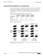
...switches Catalyst 2900 and 3500 XL switches Catalyst 5000 series/ 6000 backbone Catalyst 6000 switch Layer 3 backbone Cisco 7000 router 33021 Option 1: standalone cascaded cluster Option 2: cascaded cluster connected to a Layer 2 backbone Option 3: cascaded cluster connected to begin forwarding after a switch failure. ...XL and Catalyst 3500 XL switches in three cascaded clusters that can further reduce the time it takes cluster switches to a Layer 3 backbone Enabling UplinkFast on all cluster switches can be reduced when configuring Catalyst 2900 XL and Catalyst 3500 XL switches in...
...switches Catalyst 2900 and 3500 XL switches Catalyst 5000 series/ 6000 backbone Catalyst 6000 switch Layer 3 backbone Cisco 7000 router 33021 Option 1: standalone cascaded cluster Option 2: cascaded cluster connected to a Layer 2 backbone Option 3: cascaded cluster connected to begin forwarding after a switch failure. ...XL and Catalyst 3500 XL switches in three cascaded clusters that can further reduce the time it takes cluster switches to a Layer 3 backbone Enabling UplinkFast on all cluster switches can be reduced when configuring Catalyst 2900 XL and Catalyst 3500 XL switches in...

Software Guide
Page 165
... entries. For more slowly after a loss of switches that are always in less than 2 seconds under normal network conditions) across the switches at the access layer. The switches in 30 to the spanning-tree root fails. Links B and C are set to default values. When UplinkFast is in the STP blocking state...
... entries. For more slowly after a loss of switches that are always in less than 2 seconds under normal network conditions) across the switches at the access layer. The switches in 30 to the spanning-tree root fails. Links B and C are set to default values. When UplinkFast is in the STP blocking state...

Software Guide
Page 174
... interface interface spanning-tree rootguard end show running-config Purpose Enter global configuration mode. Configuring STP Chapter 6 Configuring the System Configuring STP Root Guard The Layer 2 network of a service provider (SP) can include many connections to . Each VLAN has its own instance of your customer's network. If a switch outside of STP...
... interface interface spanning-tree rootguard end show running-config Purpose Enter global configuration mode. Configuring STP Chapter 6 Configuring the System Configuring STP Root Guard The Layer 2 network of a service provider (SP) can include many connections to . Each VLAN has its own instance of your customer's network. If a switch outside of STP...

Software Guide
Page 205
... Catalyst 3500 Series XL Software Configuration Guide 7-7 Chapter 7 Configuring the Switch Ports Configuring UniDirectional Link Detection Configuring UniDirectional Link Detection UniDirectional Link Detection (UDLD) is a Layer 2 protocol that has both port speeds. You can try the operation again. Note You can create port groups of either Gigabit Ethernet ports or 100BASE...
... Catalyst 3500 Series XL Software Configuration Guide 7-7 Chapter 7 Configuring the Switch Ports Configuring UniDirectional Link Detection Configuring UniDirectional Link Detection UniDirectional Link Detection (UDLD) is a Layer 2 protocol that has both port speeds. You can try the operation again. Note You can create port groups of either Gigabit Ethernet ports or 100BASE...

Software Guide
Page 207
... protected ports-unicast, broadcast, and multicast-must be added to the group. Enter the second port to be forwarded through a Layer 3 device such as a router. Return to privileged EXEC mode. See the "Configuring Flooding Controls" section on the same switch is forwarded through... In such an environment, there is flooded to a protected port because a MAC address has timed out or has not been learned by the Layer 2 protocol between ports on page 7-4 for more information. Note Sometimes unknown unicast traffic from an unprotected port is no version of unicast, broadcast...
... protected ports-unicast, broadcast, and multicast-must be added to the group. Enter the second port to be forwarded through a Layer 3 device such as a router. Return to privileged EXEC mode. See the "Configuring Flooding Controls" section on the same switch is forwarded through... In such an environment, there is flooded to a protected port because a MAC address has timed out or has not been learned by the Layer 2 protocol between ports on page 7-4 for more information. Note Sometimes unknown unicast traffic from an unprotected port is no version of unicast, broadcast...

Software Guide
Page 231
... trunk connections, including Inter-Switch Link (ISL), IEEE 802.1Q, IEEE 802.10, and ATM LANE. Chapter 8 Configuring VLANs Using VTP Using VTP VTP is a Layer 2 messaging protocol that carries the traffic of multiple VLANs) or until you configure a domain name. For domain name and password configuration guidelines, see the "Domain...
... trunk connections, including Inter-Switch Link (ISL), IEEE 802.1Q, IEEE 802.10, and ATM LANE. Chapter 8 Configuring VLANs Using VTP Using VTP VTP is a Layer 2 messaging protocol that carries the traffic of multiple VLANs) or until you configure a domain name. For domain name and password configuration guidelines, see the "Domain...