
Hardware Installation Guide
Page 2
... equipment has been tested and found to provide reasonable protection against harmful interference when the equipment is causing interference by the Cisco equipment or one side or the other countries. These specifications are designed to comply with the limits for FCC compliance of Class B devices: The equipment described in part 15 of...
... equipment has been tested and found to provide reasonable protection against harmful interference when the equipment is causing interference by the Cisco equipment or one side or the other countries. These specifications are designed to comply with the limits for FCC compliance of Class B devices: The equipment described in part 15 of...

Hardware Installation Guide
Page 5
... 4-4 Speed, Duplex, and Autonegotiation 4-4 Autonegotiation and NIC Cards 4-5 Cabling Distance 4-5 Clearing the Switch IP Address and Configuration 4-5 Locating the Switch Serial Number 4-6 Technical Specifications A-1 Connector and Cable Specifications B-1 Connector Specifications B-1 10/100/1000 Ports B-1 Connecting to 10BASE-T- Contents 4 C H A P T E R A A P P E N D I X B A P P E N D I X OL-7075-09 Desk- or Shelf-Mounting (with Mounting Screws) 3-8 Wall-Mounting (with Mounting Screws...
... 4-4 Speed, Duplex, and Autonegotiation 4-4 Autonegotiation and NIC Cards 4-5 Cabling Distance 4-5 Clearing the Switch IP Address and Configuration 4-5 Locating the Switch Serial Number 4-6 Technical Specifications A-1 Connector and Cable Specifications B-1 Connector Specifications B-1 10/100/1000 Ports B-1 Connecting to 10BASE-T- Contents 4 C H A P T E R A A P P E N D I X B A P P E N D I X OL-7075-09 Desk- or Shelf-Mounting (with Mounting Screws) 3-8 Wall-Mounting (with Mounting Screws...

Hardware Installation Guide
Page 6
Contents C A P P E N D I X INDEX Console Port B-4 Cable and Adapter Specifications B-4 SFP Module Cable Specifications B-4 Two Twisted-Pair Cable Pinouts B-6 Four Twisted-Pair Cable Pinouts for 1000BASE-T Ports B-6 Crossover Cable and Adapter Pinouts B-7 Identifying a Crossover Cable B-7 Adapter Pinouts B-8 Configuring the ...
Contents C A P P E N D I X INDEX Console Port B-4 Cable and Adapter Specifications B-4 SFP Module Cable Specifications B-4 Two Twisted-Pair Cable Pinouts B-6 Four Twisted-Pair Cable Pinouts for 1000BASE-T Ports B-6 Crossover Cable and Adapter Pinouts B-7 Identifying a Crossover Cable B-7 Adapter Pinouts B-8 Configuring the ...

Hardware Installation Guide
Page 13
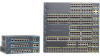
...FX SFP modules. For specific information about switch support for an optional Cisco RPS 2300 or Cisco RPS 675 redundant power system that operates on specific switches, see the Cisco Gigabit Ethernet Transceiver Modules Compatibility Matrix at this Cisco.com URL: http://www.cisco.com/en/US/docs/...; 1000BASE-SX • 1000BASE-T • 1000BASE-ZX • 100BASE-BX • 100BASE-FX • 100BASE-LX The Catalyst 2960-24PC-L, 2960-24PC-S, 2960-24LC-S, 2960-24TC-L, 2960-48TC-L, 2960-48PST-L, 2960-48PST-S, 2960G-24TC-L, and 2960G-48TC-L switches support all the SFP modules....
...FX SFP modules. For specific information about switch support for an optional Cisco RPS 2300 or Cisco RPS 675 redundant power system that operates on specific switches, see the Cisco Gigabit Ethernet Transceiver Modules Compatibility Matrix at this Cisco.com URL: http://www.cisco.com/en/US/docs/...; 1000BASE-SX • 1000BASE-T • 1000BASE-ZX • 100BASE-BX • 100BASE-FX • 100BASE-LX The Catalyst 2960-24PC-L, 2960-24PC-S, 2960-24LC-S, 2960-24TC-L, 2960-48TC-L, 2960-48PST-L, 2960-48PST-S, 2960G-24TC-L, and 2960G-48TC-L switches support all the SFP modules....

Hardware Installation Guide
Page 21
... end of the connection. The default setting is a straight-through cable. When you connect the switch to workstations, servers, routers, and Cisco IP Phones, be within 328 feet (100 meters). 100BASE-TX and 1000BASE-T traffic requires a Category 5 or higher cable. 10BASE-T traffic...Category 5 or higher cable for proper operation. Therefore, you can use the mdix auto interface configuration command in Appendix B, "Connector and Cable Specifications." When you connect the switch to switches or hubs, use either a crossover or a straight-through cable for connections to a copper 10/...
... end of the connection. The default setting is a straight-through cable. When you connect the switch to workstations, servers, routers, and Cisco IP Phones, be within 328 feet (100 meters). 100BASE-TX and 1000BASE-T traffic requires a Category 5 or higher cable. 10BASE-T traffic...Category 5 or higher cable for proper operation. Therefore, you can use the mdix auto interface configuration command in Appendix B, "Connector and Cable Specifications." When you connect the switch to switches or hubs, use either a crossover or a straight-through cable for connections to a copper 10/...

Hardware Installation Guide
Page 23
... more information about cabling requirements, see the software configuration guide. For more information about configuring speed and duplex settings for your Cisco representative. (See Figure 1-22.) OL-7075-09 Catalyst 2960 Switch Hardware Installation Guide 1-13 Dual-Purpose Port You can receive...from these SFP modules, see your SFP module documentation or the release notes for a dual-purpose uplink, see Appendix B, "Connector and Cable Specifications." Power Input Port (Catalyst 2960PD-8TT-L Switch) The Catalyst 2960PD-8TT-L can configure a dual-purpose port as either a 10/100/...
... more information about cabling requirements, see the software configuration guide. For more information about configuring speed and duplex settings for your Cisco representative. (See Figure 1-22.) OL-7075-09 Catalyst 2960 Switch Hardware Installation Guide 1-13 Dual-Purpose Port You can receive...from these SFP modules, see your SFP module documentation or the release notes for a dual-purpose uplink, see Appendix B, "Connector and Cable Specifications." Power Input Port (Catalyst 2960PD-8TT-L Switch) The Catalyst 2960PD-8TT-L can configure a dual-purpose port as either a 10/100/...

Hardware Installation Guide
Page 31
For console port and adapter pinout information, see the "Connector and Cable Specifications" section on a left and right side panels. Note The console port on the Catalyst 2960 8-port switches is 675 W. Figure 1-26 Switch Left Panel 204628 1 1 ... • Obtain status reports for the RPS power-supply module • Read and monitor backup, failure, and exception history Cisco RPS 675 The Cisco 675 RPS is a redundant power system that adapter from Cisco. You can install an optional cable lock, such as the type that is used to secure a laptop computer, to...
For console port and adapter pinout information, see the "Connector and Cable Specifications" section on a left and right side panels. Note The console port on the Catalyst 2960 8-port switches is 675 W. Figure 1-26 Switch Left Panel 204628 1 1 ... • Obtain status reports for the RPS power-supply module • Read and monitor backup, failure, and exception history Cisco RPS 675 The Cisco 675 RPS is a redundant power system that adapter from Cisco. You can install an optional cable lock, such as the type that is used to secure a laptop computer, to...

Hardware Installation Guide
Page 36
...who are authorized within the restricted access location are equipped with local and national electrical codes. Statement 1074 Guidelines for Particulate Matter Cisco Ethernet switches are made first and disconnected last. You must install this equipment in a system malfunction. When you determine where...2960 switches except for the Catalyst 2960 switch. Statement 1072 Warning No user-serviceable parts inside the chassis, which lists the cable specifications for 1000BASE-X and 100BASE-X SFP modules for the Catalyst 2960-8TC-L, 2960-8TC-S, 2960G-8TC-L, and 2960PD-8TT-L switches. Avoid...
...who are authorized within the restricted access location are equipped with local and national electrical codes. Statement 1074 Guidelines for Particulate Matter Cisco Ethernet switches are made first and disconnected last. You must install this equipment in a system malfunction. When you determine where...2960 switches except for the Catalyst 2960 switch. Statement 1072 Warning No user-serviceable parts inside the chassis, which lists the cable specifications for 1000BASE-X and 100BASE-X SFP modules for the Catalyst 2960-8TC-L, 2960-8TC-S, 2960G-8TC-L, and 2960PD-8TT-L switches. Avoid...

Hardware Installation Guide
Page 37
... supply a number-2 Phillips screwdriver to active mode during normal operation. The rear-panel power connector is within the ranges listed in Appendix A, "Technical Specifications." • Clearance to the switch, put the RPS in a rack, on a wall, or on the 1000BASE-ZX SFP module at each end..., the temperature around it might damage the cables. • Airflow around the unit does not exceed 113°F (45°C). If your Cisco representative or reseller for more information. You can easily read the front-panel indicators. - Set the RPS to rack-mount the switch. See Chapter...
... supply a number-2 Phillips screwdriver to active mode during normal operation. The rear-panel power connector is within the ranges listed in Appendix A, "Technical Specifications." • Clearance to the switch, put the RPS in a rack, on a wall, or on the 1000BASE-ZX SFP module at each end..., the temperature around it might damage the cables. • Airflow around the unit does not exceed 113°F (45°C). If your Cisco representative or reseller for more information. You can easily read the front-panel indicators. - Set the RPS to rack-mount the switch. See Chapter...

Hardware Installation Guide
Page 38
... receptacle: PWR-RPS2300, PWR675-AC-RPS-N1=. The illustrations in a partially filled rack, load the rack from the switch. The following Cisco RPS model to those switches, see Chapter 3, "Switch Installation (8-Port Switches)." Statement 370 As the switch powers on page 2-6. When the...the rack. LEDs can blink during the test. The System LED blinks green, and the other LEDs turn green. Call Cisco technical support representative if your specific switch; or Shelf-Mounting, page 2-14 Rack-Mounting This section applies to those switches, see Chapter 3, "Switch Installation ...
... receptacle: PWR-RPS2300, PWR675-AC-RPS-N1=. The illustrations in a partially filled rack, load the rack from the switch. The following Cisco RPS model to those switches, see Chapter 3, "Switch Installation (8-Port Switches)." Statement 370 As the switch powers on page 2-6. When the...the rack. LEDs can blink during the test. The System LED blinks green, and the other LEDs turn green. Call Cisco technical support representative if your specific switch; or Shelf-Mounting, page 2-14 Rack-Mounting This section applies to those switches, see Chapter 3, "Switch Installation ...

Hardware Installation Guide
Page 47
... for reliable communications. Step 1 When connecting to workstations, servers, routers, and Cisco IP Phones, connect a straight-through 3 to switches or repeaters, use a crossover cable. (See the "Cable and Adapter Specifications" section on when both the switch and the connected device have established link. ...field-replaceable modules provide the uplink optical interfaces, laser send (TX) and laser receive (RX). See the "SFP Module Cable Specifications" section on the other end might be turned on the front of the Catalyst 2960 switches. and 48-Port Switches) Installing ...
... for reliable communications. Step 1 When connecting to workstations, servers, routers, and Cisco IP Phones, connect a straight-through 3 to switches or repeaters, use a crossover cable. (See the "Cable and Adapter Specifications" section on when both the switch and the connected device have established link. ...field-replaceable modules provide the uplink optical interfaces, laser send (TX) and laser receive (RX). See the "SFP Module Cable Specifications" section on the other end might be turned on the front of the Catalyst 2960 switches. and 48-Port Switches) Installing ...
Hardware Installation Guide
Page 50
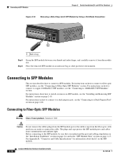
.... The plugs and caps protect the SFP module ports and cables from the module slot. For instructions on page 2-20. See Appendix B, "Connector and Cable Specifications" for information about how to install or remove an SFP module, see the "Connecting to 1000BASE-T SFP Modules" section. Connecting to SFP Modules This section...
.... The plugs and caps protect the SFP module ports and cables from the module slot. For instructions on page 2-20. See Appendix B, "Connector and Cable Specifications" for information about how to install or remove an SFP module, see the "Connecting to 1000BASE-T SFP Modules" section. Connecting to SFP Modules This section...

Hardware Installation Guide
Page 55
...; Preparing for the Catalyst 2960 Switch guide. Statement 17B OL-7075-09 Catalyst 2960 Switch Hardware Installation Guide 3-1 The installation information in this chapter is specific to the other Catalyst 2960 switches, see Chapter 2, "Switch Installation (24-
...; Preparing for the Catalyst 2960 Switch guide. Statement 17B OL-7075-09 Catalyst 2960 Switch Hardware Installation Guide 3-1 The installation information in this chapter is specific to the other Catalyst 2960 switches, see Chapter 2, "Switch Installation (24-

Hardware Installation Guide
Page 57
Never defeat the ground conductor or operate the equipment in Appendix A, "Technical Specifications." • Airflow around the switch and through an approved network termination unit with local and national electrical codes. Contact the appropriate electrical inspection ...might be greater than 10,000 feet (3,049 meters). • The bottom of the switch might be hot to the touch if the switch is specific to the other Catalyst 2960 switches, see Chapter 2, "Switch Installation (24- Statement 1074 Installation Guidelines This section is operating at the installation site must...
Never defeat the ground conductor or operate the equipment in Appendix A, "Technical Specifications." • Airflow around the switch and through an approved network termination unit with local and national electrical codes. Contact the appropriate electrical inspection ...might be greater than 10,000 feet (3,049 meters). • The bottom of the switch might be hot to the touch if the switch is specific to the other Catalyst 2960 switches, see Chapter 2, "Switch Installation (24- Statement 1074 Installation Guidelines This section is operating at the installation site must...

Hardware Installation Guide
Page 58
... and 2960PD-8TT-L switches cable guard part number: CBLGRD-C2960-8TC= • Catalyst 2960G-8TC-L switch cable guard part number: CBLGRD-C2960G-8TC= The cable guard is a different part than the cable guide, which lists the cable specifications for 1000BASE-X and 100BASE-X small form-factor (SFP) modules... and prevent them from most computer accessory suppliers. Access to manage a large number of the switch. To order a cable guard, contact your Cisco representative and use to ports is away from the switch to the other than 15.43 miles (25 km), you should insert a 5-decibel...
... and 2960PD-8TT-L switches cable guard part number: CBLGRD-C2960-8TC= • Catalyst 2960G-8TC-L switch cable guard part number: CBLGRD-C2960G-8TC= The cable guard is a different part than the cable guide, which lists the cable specifications for 1000BASE-X and 100BASE-X small form-factor (SFP) modules... and prevent them from most computer accessory suppliers. Access to manage a large number of the switch. To order a cable guard, contact your Cisco representative and use to ports is away from the switch to the other than 15.43 miles (25 km), you should insert a 5-decibel...

Hardware Installation Guide
Page 59
... POST, the System, Status, Duplex, and Speed LEDs turn off and then reflect the switch operating status. The kit part number is specific to the AC power connector on page 1-13 for support. After a successful POST, disconnect the power cord from an upstream PoE switch..... Install the switch in a rack, or on a desk, a shelf, or a wall, as described in the "Installing the Switch" section on Cisco.com describes the box contents. Chapter 3 Switch Installation (8-Port Switches) Verifying Switch Operation Installing the Catalyst 2960 8-port switches in a 19-inch rack requires...
... POST, the System, Status, Duplex, and Speed LEDs turn off and then reflect the switch operating status. The kit part number is specific to the AC power connector on page 1-13 for support. After a successful POST, disconnect the power cord from an upstream PoE switch..... Install the switch in a rack, or on a desk, a shelf, or a wall, as described in the "Installing the Switch" section on Cisco.com describes the box contents. Chapter 3 Switch Installation (8-Port Switches) Verifying Switch Operation Installing the Catalyst 2960 8-port switches in a 19-inch rack requires...

Hardware Installation Guide
Page 60
... of clearance from the adhesive strip, and attach them to complete the installation. See the switch getting started guide for instructions. 3. After the switch is specific to the other . For information applicable to the Catalyst 2960 8-port switches. The switch can be installed on page 2-20 to the recessed areas on...
... of clearance from the adhesive strip, and attach them to complete the installation. See the switch getting started guide for instructions. 3. After the switch is specific to the other . For information applicable to the Catalyst 2960 8-port switches. The switch can be installed on page 2-20 to the recessed areas on...
Hardware Installation Guide
Page 61
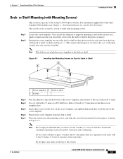
... 3 Desk or shelf 2 Screws Step 3 Step 4 Step 5 Step 6 Step 7 Peel the adhesive strip off the bottom of the desk or shelf after the switch is specific to a desk or shelf with proper clearance. Note Wait before you allow at least 3 inches (7.6 cm) of the desk or shelf. Remove the screw template...
... 3 Desk or shelf 2 Screws Step 3 Step 4 Step 5 Step 6 Step 7 Peel the adhesive strip off the bottom of the desk or shelf after the switch is specific to a desk or shelf with proper clearance. Note Wait before you allow at least 3 inches (7.6 cm) of the desk or shelf. Remove the screw template...
Hardware Installation Guide
Page 62
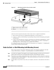
... 3 Desk or shelf 2 Screws After the switch is mounted on page 2-20 to complete the installation. or Shelf-Mounting (with Mounting Screws) This section is specific to complete the installation: 1. See the "Connecting to the 10/100 and 10/100/1000 Ports" section on page 2-14, the "Connecting to SFP Modules...
... 3 Desk or shelf 2 Screws After the switch is mounted on page 2-20 to complete the installation. or Shelf-Mounting (with Mounting Screws) This section is specific to complete the installation: 1. See the "Connecting to the 10/100 and 10/100/1000 Ports" section on page 2-14, the "Connecting to SFP Modules...
Hardware Installation Guide
Page 65
.... The steps in Figure 3-5 on page 3-12 and Figure 3-6 on page 3-13.) Warning Read the wall-mounting instructions carefully before beginning installation. The template is specific to a firmly attached plywood mounting backboard.
.... The steps in Figure 3-5 on page 3-12 and Figure 3-6 on page 3-13.) Warning Read the wall-mounting instructions carefully before beginning installation. The template is specific to a firmly attached plywood mounting backboard.
