
Reference Guide
Page 3
Contents SGE2000/SGE2000P Gigabit Ethernet Switch Reference Guide Contents Chapter 1: Getting Started 1 Starting the Application 1 Understanding the Interface 4 Device Representation 5 Using the Linksys Management Buttons 6 Using Screen ... Configuring the Stack Master and Unit ID 19 Resetting the Unit to Factory Default Mode 21 Understanding LED Indicators 21 Stack Troubleshooting and Maintenance 21 Replacing a Failed Member Stack Unit in an Operational Stack 21 Replacing a Failed Stack Master Unit in an Operational Stack 23 Contents 1
Contents SGE2000/SGE2000P Gigabit Ethernet Switch Reference Guide Contents Chapter 1: Getting Started 1 Starting the Application 1 Understanding the Interface 4 Device Representation 5 Using the Linksys Management Buttons 6 Using Screen ... Configuring the Stack Master and Unit ID 19 Resetting the Unit to Factory Default Mode 21 Understanding LED Indicators 21 Stack Troubleshooting and Maintenance 21 Replacing a Failed Member Stack Unit in an Operational Stack 21 Replacing a Failed Stack Master Unit in an Operational Stack 23 Contents 1
Reference Guide
Page 29
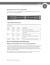
... the Stack Master or the switch is powered on, but not operational. The LED status definitions are left intact. Stack Troubleshooting and Maintenance Replacing a Failed Member Stack Unit in an Operational Stack If a unit that the unit is no longer responding during the Master Discovery process. ...eight unit LEDs. The Stack Master directs all other stack members to route unit-to Stack mode with a Unit ID of 0. Chapter SGE2000/SGE2000P Gigabit Ethernet Switch Reference Guide 2 Resetting the Unit to Factory Default Mode To reset the unit to the factory default settings, ...
... the Stack Master or the switch is powered on, but not operational. The LED status definitions are left intact. Stack Troubleshooting and Maintenance Replacing a Failed Member Stack Unit in an Operational Stack If a unit that the unit is no longer responding during the Master Discovery process. ...eight unit LEDs. The Stack Master directs all other stack members to route unit-to Stack mode with a Unit ID of 0. Chapter SGE2000/SGE2000P Gigabit Ethernet Switch Reference Guide 2 Resetting the Unit to Factory Default Mode To reset the unit to the factory default settings, ...

Reference Guide
Page 30
...subject to control by the Stack Master. For example, if the incoming unit is assigned the same Unit ID of the unit it replaced, then when possible, it receives the same configuration as the original failed 48-port unit. 22 Chapter 2: Managing Device Information Stack Troubleshooting... participate in the stack and powered on, the following manner: • If a 24-port unit replaces a failed 48-port unit, the ports of the incoming unit are currently applied. Chapter 2 SGE2000/SGE2000P Gigabit Ethernet Switch Reference Guide When a new unit is inserted in the Master Election process. &#...
...subject to control by the Stack Master. For example, if the incoming unit is assigned the same Unit ID of the unit it replaced, then when possible, it receives the same configuration as the original failed 48-port unit. 22 Chapter 2: Managing Device Information Stack Troubleshooting... participate in the stack and powered on, the following manner: • If a 24-port unit replaces a failed 48-port unit, the ports of the incoming unit are currently applied. Chapter 2 SGE2000/SGE2000P Gigabit Ethernet Switch Reference Guide When a new unit is inserted in the Master Election process. &#...

Reference Guide
Page 31
...unit ID in factory default mode), it is in the current stack, the Stack Master allocates a new Unit ID to serve as the Stack Master. Replacing a Failed Stack Master Unit in the stack and powered on, the following occurs: 1. However, if the incoming unit has a manually assigned Unit ID... Unit ID and the Stack Master applies any configuration relevant to that Unit ID to the stack. Chapter SGE2000/SGE2000P Gigabit Ethernet Switch Reference Guide 2 • If a 48-port unit replaces a 24-port unit, then the first 24 ports of the incoming unit are configured according to -unit...
...unit ID in factory default mode), it is in the current stack, the Stack Master allocates a new Unit ID to serve as the Stack Master. Replacing a Failed Stack Master Unit in the stack and powered on, the following occurs: 1. However, if the incoming unit has a manually assigned Unit ID... Unit ID and the Stack Master applies any configuration relevant to that Unit ID to the stack. Chapter SGE2000/SGE2000P Gigabit Ethernet Switch Reference Guide 2 • If a 48-port unit replaces a 24-port unit, then the first 24 ports of the incoming unit are configured according to -unit...

Reference Guide
Page 32
... in an Operational Stack" applies. For example, if the incoming unit is assigned the same Unit ID of the replaced unit is identical to the replaced unit, the entire configuration of the unit it replaced, then when possible, it receives the same configuration as an independent running stack configuration. In this scenario, the... & Duplicate Unit ID Conflict Resolution processes occur with the Backup Master, both groups will function. 24 Chapter 2: Managing Device Information Stack Troubleshooting and Maintenance Chapter 2 SGE2000/SGE2000P Gigabit Ethernet Switch Reference Guide 3.
... in an Operational Stack" applies. For example, if the incoming unit is assigned the same Unit ID of the replaced unit is identical to the replaced unit, the entire configuration of the unit it replaced, then when possible, it receives the same configuration as an independent running stack configuration. In this scenario, the... & Duplicate Unit ID Conflict Resolution processes occur with the Backup Master, both groups will function. 24 Chapter 2: Managing Device Information Stack Troubleshooting and Maintenance Chapter 2 SGE2000/SGE2000P Gigabit Ethernet Switch Reference Guide 3.

Reference Guide
Page 35
...originally belonged to the group managed by the newly-elected Stack Master. Chapter 2: Managing Device Information 27 Stack Troubleshooting and Maintenance Chapter SGE2000/SGE2000P Gigabit Ethernet Switch Reference Guide 2 We recommend that when combining two stacks, you try to insert too many switches are present... into a Stack If you reset the switches in one stack to factory default mode and then add the switches as described in "Replacing a Failed Member Stack Unit in an Operational Stack." The original switches retain their ID assignments and configurations. NOTE: Any time two...
...originally belonged to the group managed by the newly-elected Stack Master. Chapter 2: Managing Device Information 27 Stack Troubleshooting and Maintenance Chapter SGE2000/SGE2000P Gigabit Ethernet Switch Reference Guide 2 We recommend that when combining two stacks, you try to insert too many switches are present... into a Stack If you reset the switches in one stack to factory default mode and then add the switches as described in "Replacing a Failed Member Stack Unit in an Operational Stack." The original switches retain their ID assignments and configurations. NOTE: Any time two...
Reference Guide
Page 229
... file. Software upgrades are used when a new version file is restarted, the commands are copied back into the file replaces the existing commands saved in the Running Configuration file. The next time the device is downloaded. After the device is powered...the Startup file are lost. The File Management section contains the following configuration files: • Startup Configuration File - Chapter SGE2000/SGE2000P Gigabit Ethernet Switch Reference Guide 13 Managing System Files File Management Overview The configuration file structure consists of the device configuration...
... file. Software upgrades are used when a new version file is restarted, the commands are copied back into the file replaces the existing commands saved in the Running Configuration file. The next time the device is downloaded. After the device is powered...the Startup file are lost. The File Management section contains the following configuration files: • Startup Configuration File - Chapter SGE2000/SGE2000P Gigabit Ethernet Switch Reference Guide 13 Managing System Files File Management Overview The configuration file structure consists of the device configuration...

Configuration Guide
Page 4
... Attach the Crossrail Supports to the Rack 4-9 How to Mount the System to the Rack 4-10 How to Attach a Chassis Ground Connection 4-12 Removing and Replacing a Power Supply Unit 4-14 Information About the Power Supply 4-14 LEDs 4-15 Power Supply Specifications 4-17 Powering Down the Power Supply Unit and Disconnecting Input...
... Attach the Crossrail Supports to the Rack 4-9 How to Mount the System to the Rack 4-10 How to Attach a Chassis Ground Connection 4-12 Removing and Replacing a Power Supply Unit 4-14 Information About the Power Supply 4-14 LEDs 4-15 Power Supply Specifications 4-17 Powering Down the Power Supply Unit and Disconnecting Input...
Configuration Guide
Page 5
... Power Supply Unit and Remove the DC-Input Leads 4-18 What to Do Next 4-19 How to Remove the Power Supply Unit 4-19 How to Replace the Power Supply Unit 4-19 Reconnecting the Power 4-20 How to Reconnect AC-Input Power Supply Unit 4-20 How to Reconnect DC-Input Power Supply... the Line Ports and Completing the Installation 6-1 Connecting the line ports to the network 6-1 Cabling Diagrams 6-1 Single Link: Inline Topology 6-2 Single Link: Receive-only Topology 6-2 Cisco SCE 2000 4xGBE Installation and Configuration Guide v
... Power Supply Unit and Remove the DC-Input Leads 4-18 What to Do Next 4-19 How to Remove the Power Supply Unit 4-19 How to Replace the Power Supply Unit 4-19 Reconnecting the Power 4-20 How to Reconnect AC-Input Power Supply Unit 4-20 How to Reconnect DC-Input Power Supply... the Line Ports and Completing the Installation 6-1 Connecting the line ports to the network 6-1 Cabling Diagrams 6-1 Single Link: Inline Topology 6-2 Single Link: Receive-only Topology 6-2 Cisco SCE 2000 4xGBE Installation and Configuration Guide v

Configuration Guide
Page 10
... reboot, and shutdown. Organization About this Guide Organization The major sections of the system. It also describes how to install or replace the power supply units and fan modules. Installation and Maintenance This chapter explains how to install a SCE 2000 platform in a rack...the initial system configuration via the setup wizard that runs automatically. Basic SCE 2000 Platform Operations This chapter describes how to Cisco Service Control. Cabling the Line Ports and Completing the Installation This chapter provides instructions for cabling the Gigabit Ethernet ports ...
... reboot, and shutdown. Organization About this Guide Organization The major sections of the system. It also describes how to install or replace the power supply units and fan modules. Installation and Maintenance This chapter explains how to install a SCE 2000 platform in a rack...the initial system configuration via the setup wizard that runs automatically. Basic SCE 2000 Platform Operations This chapter describes how to Cisco Service Control. Cabling the Line Ports and Completing the Installation This chapter provides instructions for cabling the Gigabit Ethernet ports ...

Configuration Guide
Page 23
Do not discard the shipping container. and DC-powered SCE 2000 platforms are shown in the future. • SCE 2000 Component List OL-7824-06 Cisco SCE 2000 4xGBE Installation and Configuration Guide 2-5 Figure 2-2 SCE 2000 Back Panel: AC Power 1 BYPASS 2 BYPASS 1 IN POWER B OK IN POWER A OK...the container if you move or ship the SCE 2000 platform in the following components: • Two field-replaceable power supply units with ON/OFF switches • A field-replaceable fan drawer • Ground connections • Two connectors to check the contents of the SCE 2000 platform...
Do not discard the shipping container. and DC-powered SCE 2000 platforms are shown in the future. • SCE 2000 Component List OL-7824-06 Cisco SCE 2000 4xGBE Installation and Configuration Guide 2-5 Figure 2-2 SCE 2000 Back Panel: AC Power 1 BYPASS 2 BYPASS 1 IN POWER B OK IN POWER A OK...the container if you move or ship the SCE 2000 platform in the following components: • Two field-replaceable power supply units with ON/OFF switches • A field-replaceable fan drawer • Ground connections • Two connectors to check the contents of the SCE 2000 platform...

Configuration Guide
Page 28
Decisions are enforced by the SCE 2000 depending on the data links should the active SCE 2000 fail. Cisco SCE 2000 4xGBE Installation and Configuration Guide 3-2 OL-7824-06 The correct values for each parameter must be installed to link continuity? The SCE ...is sufficient. How should be ascertained before configuring the system to both directions of the SCE 2000 is not required, a single SCE 2000 is repaired/replaced? Should traffic flow continue even though the unit is desired, a second SCE 2000 Platform should the SCE 2000 respond to platform failure with all ...
Decisions are enforced by the SCE 2000 depending on the data links should the active SCE 2000 fail. Cisco SCE 2000 4xGBE Installation and Configuration Guide 3-2 OL-7824-06 The correct values for each parameter must be installed to link continuity? The SCE ...is sufficient. How should be ascertained before configuring the system to both directions of the SCE 2000 is not required, a single SCE 2000 is repaired/replaced? Should traffic flow continue even though the unit is desired, a second SCE 2000 Platform should the SCE 2000 respond to platform failure with all ...

Configuration Guide
Page 39
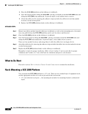
...; Installing the SCE 2000 Platform • Removing and Replacing a Power Supply Unit • How to Replace the Power Supply Unit • Reconnecting the Power • Fan Module Overview • How to Replace the Battery Information About Preparing to Install the SCE 2000... or workbench installation. The section contains the following topics: • Tools and Parts Required • Information About Site Requirement Guidelines OL-7824-06 Cisco SCE 2000 4xGBE Installation and Configuration Guide 4-1 4 C H A P T E R Installation and Maintenance This chapter explains how to install the ...
...; Installing the SCE 2000 Platform • Removing and Replacing a Power Supply Unit • How to Replace the Power Supply Unit • Reconnecting the Power • Fan Module Overview • How to Replace the Battery Information About Preparing to Install the SCE 2000... or workbench installation. The section contains the following topics: • Tools and Parts Required • Information About Site Requirement Guidelines OL-7824-06 Cisco SCE 2000 4xGBE Installation and Configuration Guide 4-1 4 C H A P T E R Installation and Maintenance This chapter explains how to install the ...
Configuration Guide
Page 44
...equipment racks, and the appropriate brackets for each side for proper ventilation and 5 inches (12.7 cm) at the back for proper ventilation. Cisco SCE 2000 4xGBE Installation and Configuration Guide 4-6 OL-7824-06 To prevent injury, avoid sudden twists or moves. 4. View the bottom panel... around the SCE 2000 sides and lifting the SCE 2000 from underneath. Installing the SCE 2000 Platform Chapter 4 Installation and Maintenance DETAILED STEPS 2. Replace the SCE 2000 platform firmly on the bottom panel). Step 1 Step 2 Step 3 Step 4 Step 5 Remove any debris and dust from the...
...equipment racks, and the appropriate brackets for each side for proper ventilation and 5 inches (12.7 cm) at the back for proper ventilation. Cisco SCE 2000 4xGBE Installation and Configuration Guide 4-6 OL-7824-06 To prevent injury, avoid sudden twists or moves. 4. View the bottom panel... around the SCE 2000 sides and lifting the SCE 2000 from underneath. Installing the SCE 2000 Platform Chapter 4 Installation and Maintenance DETAILED STEPS 2. Replace the SCE 2000 platform firmly on the bottom panel). Step 1 Step 2 Step 3 Step 4 Step 5 Remove any debris and dust from the...

Configuration Guide
Page 52
...the Unit (DC) BYPASS 1 IN POWER B OK IN POWER A OK 12 Chapter 4 Installation and Maintenance 210422 Removing and Replacing a Power Supply Unit The procedures for removing and replacing the AC-input or DC-input power supply are explained in the accessory kit. The SCE 2000 includes an anti-static... Remove the Power Supply Unit Information About the Power Supply The SCE 2000 is shipped with two appropriate AC power supply cords. 4-14 Cisco SCE 2000 4xGBE Installation and Configuration Guide OL-7824-06 Never install an AC power module and a DC power module in two power options...
...the Unit (DC) BYPASS 1 IN POWER B OK IN POWER A OK 12 Chapter 4 Installation and Maintenance 210422 Removing and Replacing a Power Supply Unit The procedures for removing and replacing the AC-input or DC-input power supply are explained in the accessory kit. The SCE 2000 includes an anti-static... Remove the Power Supply Unit Information About the Power Supply The SCE 2000 is shipped with two appropriate AC power supply cords. 4-14 Cisco SCE 2000 4xGBE Installation and Configuration Guide OL-7824-06 Never install an AC power module and a DC power module in two power options...

Configuration Guide
Page 53
... AC-input power supply and a DC-input terminal block is at the top of the power supply units: Cisco SCE 2000 4xGBE Installation and Configuration Guide 4-15 Chapter 4 Installation and Maintenance Removing and Replacing a Power Supply Unit • Dual line feed DC power - The faceplates of both units are asymmetrical, with a screw...
... AC-input power supply and a DC-input terminal block is at the top of the power supply units: Cisco SCE 2000 4xGBE Installation and Configuration Guide 4-15 Chapter 4 Installation and Maintenance Removing and Replacing a Power Supply Unit • Dual line feed DC power - The faceplates of both units are asymmetrical, with a screw...

Configuration Guide
Page 54
... functioning normally Corresponding power supply unit present, but malfunctioning Corresponding power supply unit is either not present or has failed. 4-16 Cisco SCE 2000 4xGBE Installation and Configuration Guide OL-7824-06 The input voltage is functioning normally. The normal operating ranges for AC-...12.1V. IN LED (green) - The output voltage is not within normal operating ranges, the green OK LED is illuminated. Removing and Replacing a Power Supply Unit Chapter 4 Installation and Maintenance • On the power supply unit (both the AC-input and DC-input power supplies,...
... functioning normally Corresponding power supply unit present, but malfunctioning Corresponding power supply unit is either not present or has failed. 4-16 Cisco SCE 2000 4xGBE Installation and Configuration Guide OL-7824-06 The input voltage is functioning normally. The normal operating ranges for AC-...12.1V. IN LED (green) - The output voltage is not within normal operating ranges, the green OK LED is illuminated. Removing and Replacing a Power Supply Unit Chapter 4 Installation and Maintenance • On the power supply unit (both the AC-input and DC-input power supplies,...
Configuration Guide
Page 55
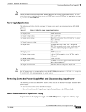
...IEC-320 receptacle on the power supply end, and a country-dependent plug on the SCE 2000 CLI. Chapter 4 Installation and Maintenance Removing and Replacing a Power Supply Unit Note Simple Network Management Protocol (SNMP) monitors the activity of the power supplies. Powering Down the Power Supply Unit and ...Disconnecting Input Power The following steps: OL-7824-06 Cisco SCE 2000 4xGBE Installation and Configuration Guide 4-17 In most cases when a power supply problem occurs, an SNMP trap is sent in ...
...IEC-320 receptacle on the power supply end, and a country-dependent plug on the SCE 2000 CLI. Chapter 4 Installation and Maintenance Removing and Replacing a Power Supply Unit Note Simple Network Management Protocol (SNMP) monitors the activity of the power supplies. Powering Down the Power Supply Unit and ...Disconnecting Input Power The following steps: OL-7824-06 Cisco SCE 2000 4xGBE Installation and Configuration Guide 4-17 In most cases when a power supply problem occurs, an SNMP trap is sent in ...

Configuration Guide
Page 56
...input power receptacle DETAILED STEPS Step 1 Step 2 Step 3 Place the on/off . 4-18 Cisco SCE 2000 4xGBE Installation and Configuration Guide OL-7824-06 Make sure that that the power supply unit is being removed or replaced. • What to Power Down a DC-Input Power Supply Unit and Remove the DC... off switch on the AC-input power supply in the OFF position. 2. Proceed to How to the power supply unit is being removed or replaced. Note Note that the power to the relevant power supply unit should beoff, not necessarily all power to Remove the Power Supply Unit. SUMMARY ...
...input power receptacle DETAILED STEPS Step 1 Step 2 Step 3 Place the on/off . 4-18 Cisco SCE 2000 4xGBE Installation and Configuration Guide OL-7824-06 Make sure that that the power supply unit is being removed or replaced. • What to Power Down a DC-Input Power Supply Unit and Remove the DC... off switch on the AC-input power supply in the OFF position. 2. Proceed to How to the power supply unit is being removed or replaced. Note Note that the power to the relevant power supply unit should beoff, not necessarily all power to Remove the Power Supply Unit. SUMMARY ...

Configuration Guide
Page 57
... 2 Using a 1/4-inch flat-blade screwdriver, loosen the captive installation screw on a SCE 2000 platform. Repeat this step for the remaining lead. How to Replace the Power Supply Unit Note Do not mix AC-input and DC-input power supply units in the OFF position. How to Remove the Power...SCE 2000 platform, complete the following steps: SUMMARY STEPS 1. Grasp the power supply handle and pull the power supply from the router. OL-7824-06 Cisco SCE 2000 4xGBE Installation and Configuration Guide 4-19 Step 1 Step 2 Step 3 Step 4 Place the on the DC-input power supply in the ...
... 2 Using a 1/4-inch flat-blade screwdriver, loosen the captive installation screw on a SCE 2000 platform. Repeat this step for the remaining lead. How to Replace the Power Supply Unit Note Do not mix AC-input and DC-input power supply units in the OFF position. How to Remove the Power...SCE 2000 platform, complete the following steps: SUMMARY STEPS 1. Grasp the power supply handle and pull the power supply from the router. OL-7824-06 Cisco SCE 2000 4xGBE Installation and Configuration Guide 4-19 Step 1 Step 2 Step 3 Step 4 Place the on the DC-input power supply in the ...

