Reference Guide
Page 4
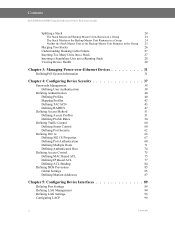
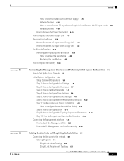
Contents SGE2000/SGE2000P Gigabit Ethernet Switch Reference Guide Splitting a Stack 24 The Stack Master and Backup Master Units Remain in a Group 24 The Stack Master or the Backup Master Unit Remains in a Group 24 Neither the Stack Master Unit or the Backup Master Unit Remains in ...Profiles 51 Defining Profile Rules 54 Defining Traffic Control 60 Defining Storm Control 60 Defining Port Security 62 Defining 802.1x 66 Defining 802.1X Properties 67 Defining Port Authentication 68 Defining Multiple Hosts 71 Defining Authenticated Host 74 Defining Access Control 75 ...
Contents SGE2000/SGE2000P Gigabit Ethernet Switch Reference Guide Splitting a Stack 24 The Stack Master and Backup Master Units Remain in a Group 24 The Stack Master or the Backup Master Unit Remains in a Group 24 Neither the Stack Master Unit or the Backup Master Unit Remains in ...Profiles 51 Defining Profile Rules 54 Defining Traffic Control 60 Defining Storm Control 60 Defining Port Security 62 Defining 802.1x 66 Defining 802.1X Properties 67 Defining Port Authentication 68 Defining Multiple Hosts 71 Defining Authenticated Host 74 Defining Access Control 75 ...
Reference Guide
Page 21
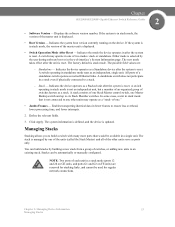
...reset. Define the relevant fields. 3. Managing Stacks Stacking allows you to build a switch with many more ports than would be available in a stack even if physically connected to a stack. - Standalone - A...operate in stack mode, the version of two modes: stack or standalone. Stack - Chapter SGE2000/SGE2000P Gigabit Ethernet Switch Reference Guide 2 • Software Version - If the system is...adding new units to six Stack Member switches. NOTE: Two ports of a standalone switch operate as ports only. All ports of each unit in after the system is in one Master...
...reset. Define the relevant fields. 3. Managing Stacks Stacking allows you to build a switch with many more ports than would be available in a stack even if physically connected to a stack. - Standalone - A...operate in stack mode, the version of two modes: stack or standalone. Stack - Chapter SGE2000/SGE2000P Gigabit Ethernet Switch Reference Guide 2 • Software Version - If the system is...adding new units to six Stack Member switches. NOTE: Two ports of a standalone switch operate as ports only. All ports of each unit in after the system is in one Master...

Reference Guide
Page 30
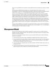
...not occur. 2. If the incoming unit is not identical to the unit that is relevant to the number assigned to the stack. 3. Chapter 2 SGE2000/SGE2000P Gigabit Ethernet Switch Reference Guide When a new unit is inserted in the Master Election process. • If the incoming unit has a Unit ID..., performs the Master Discovery process, and may participate in the stack and powered on, the following manner: • If a 24-port unit replaces a failed 48-port unit, the ports of the incoming unit are currently applied. If the incoming unit cannot be assigned an available Unit ID, then it is shut...
...not occur. 2. If the incoming unit is not identical to the unit that is relevant to the number assigned to the stack. 3. Chapter 2 SGE2000/SGE2000P Gigabit Ethernet Switch Reference Guide When a new unit is inserted in the Master Election process. • If the incoming unit has a Unit ID..., performs the Master Discovery process, and may participate in the stack and powered on, the following manner: • If a 24-port unit replaces a failed 48-port unit, the ports of the incoming unit are currently applied. If the incoming unit cannot be assigned an available Unit ID, then it is shut...

Reference Guide
Page 31
...as the Stack Master. The Backup Master (now the Stack Master) directs all other stack members to route unit-to configuration of the ports of the failed unit. We recommend that you use the automatically-assigned unit ID mode because it provides better resiliency to the stack. ... Backup Master, while the current unit with a Unit ID of 1 to the stack. Chapter SGE2000/SGE2000P Gigabit Ethernet Switch Reference Guide 2 • If a 48-port unit replaces a 24-port unit, then the first 24 ports of the incoming unit are left intact. Replacing a Failed Stack Master Unit in the stack and...
...as the Stack Master. The Backup Master (now the Stack Master) directs all other stack members to route unit-to configuration of the ports of the failed unit. We recommend that you use the automatically-assigned unit ID mode because it provides better resiliency to the stack. ... Backup Master, while the current unit with a Unit ID of 1 to the stack. Chapter SGE2000/SGE2000P Gigabit Ethernet Switch Reference Guide 2 • If a 48-port unit replaces a 24-port unit, then the first 24 ports of the incoming unit are left intact. Replacing a Failed Stack Master Unit in the stack and...

Reference Guide
Page 32
... & Duplicate Unit ID Conflict Resolution processes occur with the Backup Master, both groups will function. 24 Chapter 2: Managing Device Information Stack Troubleshooting and Maintenance Chapter 2 SGE2000/SGE2000P Gigabit Ethernet Switch Reference Guide 3. They are performed in two groups, one with the Stack...not present." For each of the split stacks. • The Stack Master notifies the system administrator of the removed units and ports that belong to the unreachable units by the Stack Master includes only units that are reachable (connected) following results: •...
... & Duplicate Unit ID Conflict Resolution processes occur with the Backup Master, both groups will function. 24 Chapter 2: Managing Device Information Stack Troubleshooting and Maintenance Chapter 2 SGE2000/SGE2000P Gigabit Ethernet Switch Reference Guide 3. They are performed in two groups, one with the Stack...not present." For each of the split stacks. • The Stack Master notifies the system administrator of the removed units and ports that belong to the unreachable units by the Stack Master includes only units that are reachable (connected) following results: •...

Software Configuration Guide
Page 4
...16 Associating a Fabric Extender to a Port Channel 17 Disassociating a Fabric Extender From an Interface 19 Associating a Fabric Extender to an F2 Module 19 Configuring Fabric Extender Global Features 21 Configuration Examples 23 Configuring a FEX with a Layer 3 Host Interface 24 Configuring a Host Interface in a ... to Two FEXs 24 Dual-homing of a Server to a FEX with FabricPath 25 Verifying the Configuration 26 Verifying the Fabric Extender Configuration 26 Verifying the Chassis Management Information 29 Additional References 33 Related Documents 33 Feature History 33 Cisco Nexus 2000 Series ...
...16 Associating a Fabric Extender to a Port Channel 17 Disassociating a Fabric Extender From an Interface 19 Associating a Fabric Extender to an F2 Module 19 Configuring Fabric Extender Global Features 21 Configuration Examples 23 Configuring a FEX with a Layer 3 Host Interface 24 Configuring a Host Interface in a ... to Two FEXs 24 Dual-homing of a Server to a FEX with FabricPath 25 Verifying the Configuration 26 Verifying the Fabric Extender Configuration 26 Verifying the Chassis Management Information 29 Additional References 33 Related Documents 33 Feature History 33 Cisco Nexus 2000 Series ...
Software Configuration Guide
Page 17
... displayed using the switch commands for the Cisco Nexus 2232TM is 4:1. When its operational status. The Cisco Nexus 2248TP-E Fabric Extender has 4 10-Gigabit Ethernet fabric interfaces and 48 100/1000BASE-T (100-Mb/1-Gigabit) Ethernet host interfaces. Port-channel mode is not supported. After discovery...to all of the available fabric interfaces. (Static pinning is managed by detecting the fabric interfaces of loopback addresses (127.15.1.0/24) to the Fabric Extender to avoid conflicts with no oversubscription when its parent switch over the fabric interfaces through a zero-touch...
... displayed using the switch commands for the Cisco Nexus 2232TM is 4:1. When its operational status. The Cisco Nexus 2248TP-E Fabric Extender has 4 10-Gigabit Ethernet fabric interfaces and 48 100/1000BASE-T (100-Mb/1-Gigabit) Ethernet host interfaces. Port-channel mode is not supported. After discovery...to all of the available fabric interfaces. (Static pinning is managed by detecting the fabric interfaces of loopback addresses (127.15.1.0/24) to the Fabric Extender to avoid conflicts with no oversubscription when its parent switch over the fabric interfaces through a zero-touch...

Software Configuration Guide
Page 28
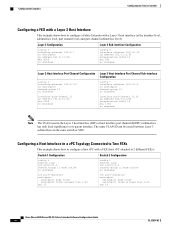
... interface, not from the physical interface. If you try to associate a physical port to a FEX before that physical port is joined to a port channel, the physical port moves to the err-disable state and the Cisco Nexus 7000 series device does not communicate with the FEX on that this does ... port-channel 4 fex-intf Fabric FEX Interface Interfaces Po4 Eth101/1/48 Eth101/1/47 Eth101/1/46 Eth101/1/44 Eth101/1/43 Eth101/1/42 Eth101/1/40 Eth101/1/39 Eth101/1/38 Eth101/1/36 Eth101/1/35 Eth101/1/34 Eth101/1/32 Eth101/1/31 Eth101/1/30 Eth101/1/28 Eth101/1/27 Eth101/1/26 Eth101/1/24 ...
... interface, not from the physical interface. If you try to associate a physical port to a FEX before that physical port is joined to a port channel, the physical port moves to the err-disable state and the Cisco Nexus 7000 series device does not communicate with the FEX on that this does ... port-channel 4 fex-intf Fabric FEX Interface Interfaces Po4 Eth101/1/48 Eth101/1/47 Eth101/1/46 Eth101/1/44 Eth101/1/43 Eth101/1/42 Eth101/1/40 Eth101/1/39 Eth101/1/38 Eth101/1/36 Eth101/1/35 Eth101/1/34 Eth101/1/32 Eth101/1/31 Eth101/1/30 Eth101/1/28 Eth101/1/27 Eth101/1/26 Eth101/1/24 ...
Software Configuration Guide
Page 34
... config t interface ethernet 101/1/1 no switchport ip address 192.0.1.1/24 Mtu 9000 no shutdown config t interface ethernet 101/1/1.12 ip address 192.0.2.1/24 encapsulation dot1Q 12 mtu 850 no shutdown Layer 3 Host Interface Port Channel Configuration config t interface ethernet 101/1/1-2 no switchport channel-... switchport channel-group 12 no shutdown interface port-channel 12.14 ip address 192.0.4.1/24 encapsulation dot1Q 14 mtu 1700 no shutdown Int port-channel10 switchport switchport mode trunk switchport trunk allowed vlan 1-20 vpc 10 Cisco Nexus 2000 Series NX-OS Fabric Extender ...
... config t interface ethernet 101/1/1 no switchport ip address 192.0.1.1/24 Mtu 9000 no shutdown config t interface ethernet 101/1/1.12 ip address 192.0.2.1/24 encapsulation dot1Q 12 mtu 850 no shutdown Layer 3 Host Interface Port Channel Configuration config t interface ethernet 101/1/1-2 no switchport channel-... switchport channel-group 12 no shutdown interface port-channel 12.14 ip address 192.0.4.1/24 encapsulation dot1Q 14 mtu 1700 no shutdown Int port-channel10 switchport switchport mode trunk switchport trunk allowed vlan 1-20 vpc 10 Cisco Nexus 2000 Series NX-OS Fabric Extender ...

Software Configuration Guide
Page 37
... state: Po101 - State: Active Eth2/1 - Interface Up. Interface Up. State: Active Fex Port State Fabric Port Primary Fabric Eth101/1/1 Up Po101 Po101 Eth101/1/2 Up Po101 Po101 Eth101/1/3 Down Po101 Po101 Eth101/1/4 ... Po101 Po101 Eth101/1/22 Down Po101 Po101 Eth101/1/23 Down Po101 Po101 Eth101/1/24 Down Po101 Po101 Eth101/1/25 Down Po101 Po101 Eth101/1/26 Down Po101 Po101 ... Po101 Eth101/1/28 Down Po101 Po101 Eth101/1/29 Down Po101 Po101 OL-25816-02 Cisco Nexus 2000 Series NX-OS Fabric Extender Software Configuration Guide 27 State: Active Eth4...
... state: Po101 - State: Active Eth2/1 - Interface Up. Interface Up. State: Active Fex Port State Fabric Port Primary Fabric Eth101/1/1 Up Po101 Po101 Eth101/1/2 Up Po101 Po101 Eth101/1/3 Down Po101 Po101 Eth101/1/4 ... Po101 Po101 Eth101/1/22 Down Po101 Po101 Eth101/1/23 Down Po101 Po101 Eth101/1/24 Down Po101 Po101 Eth101/1/25 Down Po101 Po101 Eth101/1/26 Down Po101 Po101 ... Po101 Eth101/1/28 Down Po101 Po101 Eth101/1/29 Down Po101 Po101 OL-25816-02 Cisco Nexus 2000 Series NX-OS Fabric Extender Software Configuration Guide 27 State: Active Eth4...
Configuration Guide
Page 5
...to Reconnect DC-Input Power Supply Unit 4-21 Fan Module Overview 4-23 Removing and Replacing the Fan Module 4-24 How to Remove the Fan Module 4-24 Replacing the Fan Module 4-25 How to Replace the Battery 4-26 Connecting the Management Interfaces and Performing Initial System... the Configuration 5-23 Connecting the Management Interface 5-25 How to Cable the Management Port 5-25 How to Verify Management Interface Connectivity 5-26 Cabling the Line Ports and Completing the Installation 6-1 Connecting the line ports to the network 6-1 Cabling Diagrams 6-1 Single Link: Inline Topology 6-2 Single Link...
...to Reconnect DC-Input Power Supply Unit 4-21 Fan Module Overview 4-23 Removing and Replacing the Fan Module 4-24 How to Remove the Fan Module 4-24 Replacing the Fan Module 4-25 How to Replace the Battery 4-26 Connecting the Management Interfaces and Performing Initial System... the Configuration 5-23 Connecting the Management Interface 5-25 How to Cable the Management Port 5-25 How to Verify Management Interface Connectivity 5-26 Cabling the Line Ports and Completing the Installation 6-1 Connecting the line ports to the network 6-1 Cabling Diagrams 6-1 Single Link: Inline Topology 6-2 Single Link...
Configuration Guide
Page 24
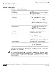
...supports for 19" rack with front and back posts • Fast Ethernet cable for connecting to the Management ports • RS-232 serial cable (DB-9 to RJ-45) for tabletop installation • 1 External Optical... You must specifically order the documentation as part of documentation sets when you within 24 hours. You must order the type and quantity of the sales order. To order... Two spring washers (#¼") If ordered, SCE 2000 hardware and software documentation set and the Cisco Documentation CD-ROM package* Four rubber feet for connecting to the SCE Platform SCE 2000 Component ...
...supports for 19" rack with front and back posts • Fast Ethernet cable for connecting to the Management ports • RS-232 serial cable (DB-9 to RJ-45) for tabletop installation • 1 External Optical... You must specifically order the documentation as part of documentation sets when you within 24 hours. You must order the type and quantity of the sales order. To order... Two spring washers (#¼") If ordered, SCE 2000 hardware and software documentation set and the Cisco Documentation CD-ROM package* Four rubber feet for connecting to the SCE Platform SCE 2000 Component ...


