Quick Start Guide
Page 5
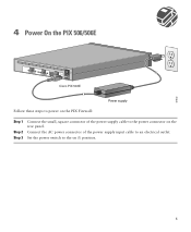
4 Power On the PIX 506/506E ACT LINK ETHERNET 1 ACT LINK ETHERNET 0 DC POWER USB CONSOLE INPUT DC POWER INPUT Cisco PIX 506E Power supply Follow these steps to power on the PIX Firewall: Step 1 Step 2 Step 3 Connect the small, square connector of the power supply input cable to an electrical outlet. Set the power switch to the power connector on (|) position. 67932 5 Connect the AC power connector of the power supply cable to the on the rear panel.
4 Power On the PIX 506/506E ACT LINK ETHERNET 1 ACT LINK ETHERNET 0 DC POWER USB CONSOLE INPUT DC POWER INPUT Cisco PIX 506E Power supply Follow these steps to power on the PIX Firewall: Step 1 Step 2 Step 3 Connect the small, square connector of the power supply input cable to an electrical outlet. Set the power switch to the power connector on (|) position. 67932 5 Connect the AC power connector of the power supply cable to the on the rear panel.

