
Installation Guide
Page 28
... current traffic load over the backplane. Flashing The link is detected. 1. An overtemperature condition has occurred. (A minor threshold has been exceeded during environmental monitoring.) All chassis environmental monitors are reporting OK. The VTT module terminates signals on a redundant supervisor engine are installed. Orange The power supply or power supply fan failed...
... current traffic load over the backplane. Flashing The link is detected. 1. An overtemperature condition has occurred. (A minor threshold has been exceeded during environmental monitoring.) All chassis environmental monitors are reporting OK. The VTT module terminates signals on a redundant supervisor engine are installed. Orange The power supply or power supply fan failed...

Installation Guide
Page 29
... is in standby mode. the module is bad. Minor hardware problems. An overtemperature condition has occurred. (A major threshold has been exceeded during environmental monitoring.) All chassis environmental monitors are synchronized to the active supervisor engine. The temperature of the supervisor engine major threshold has been exceeded. The SYSTEM and PWR MGMT...
... is in standby mode. the module is bad. Minor hardware problems. An overtemperature condition has occurred. (A major threshold has been exceeded during environmental monitoring.) All chassis environmental monitors are synchronized to the active supervisor engine. The temperature of the supervisor engine major threshold has been exceeded. The SYSTEM and PWR MGMT...

Installation Guide
Page 30
...disabled. Minor hardware problems. An overtemperature condition has occurred. (A major threshold has been exceeded during environmental monitoring.) All chassis environmental monitors are reporting OK. The temperature of the supervisor engine major threshold has been exceeded. Red Major hardware problem... stall. Supervisor Engines Chapter 1 Product Overview Table 1-5 Supervisor Engine 32 LEDs (continued) LED SYSTEM1 Color Green Description All chassis environmental monitors are reporting OK. the module is powering up or a minor hardware fault has occurred. The SYSTEM and PWR...
...disabled. Minor hardware problems. An overtemperature condition has occurred. (A major threshold has been exceeded during environmental monitoring.) All chassis environmental monitors are reporting OK. The temperature of the supervisor engine major threshold has been exceeded. Red Major hardware problem... stall. Supervisor Engines Chapter 1 Product Overview Table 1-5 Supervisor Engine 32 LEDs (continued) LED SYSTEM1 Color Green Description All chassis environmental monitors are reporting OK. the module is powering up or a minor hardware fault has occurred. The SYSTEM and PWR...

Installation Guide
Page 32
... full-duplex mode only. Supervisor Engines Chapter 1 Product Overview Note To access the port mode switch, use a ballpoint pen tip or other ports in the chassis.
... full-duplex mode only. Supervisor Engines Chapter 1 Product Overview Note To access the port mode switch, use a ballpoint pen tip or other ports in the chassis.

Installation Guide
Page 53
...identifies the physical port number on page 1-37. OL-5077-7 Book Title 1-37 Chapter 1 Product Overview Port Addresses Table 1-26 LED Label STATUS A/L Cisco 7600 ES+ 40G3C, -40G3CXL Line Card LEDs Color Red Green Yellow Off Amber State On On On Off On Green On Green and On Amber...connector within the system and to bottom. Port Addresses Each port (or interface) in the Cisco 7600 series router is a two-part number in the three-slot, four-slot, six-slot, nine-slot, and thirteen-slot chassis.) The address is designated by software. The number of additional ports (n/1, n/2, and so on...
...identifies the physical port number on page 1-37. OL-5077-7 Book Title 1-37 Chapter 1 Product Overview Port Addresses Table 1-26 LED Label STATUS A/L Cisco 7600 ES+ 40G3C, -40G3CXL Line Card LEDs Color Red Green Yellow Off Amber State On On On Off On Green On Green and On Amber...connector within the system and to bottom. Port Addresses Each port (or interface) in the Cisco 7600 series router is a two-part number in the three-slot, four-slot, six-slot, nine-slot, and thirteen-slot chassis.) The address is designated by software. The number of additional ports (n/1, n/2, and so on...

Installation Guide
Page 55
...removed modules, and places them in the bus and should be removed. When you must first remove the FlexWAN module from the chassis and then replace port adapters as if they were in the administratively shutdown state, as required. If the new module is operating ...normally. Power Management and Environmental Monitoring For detailed information on the module back to the Cisco 7600 Series Internet Router Software Configuration Guide. Chapter 1 Product Overview Hot Swapping Supervisor Engines and Modules Hot Swapping Supervisor Engines and ...
...removed modules, and places them in the bus and should be removed. When you must first remove the FlexWAN module from the chassis and then replace port adapters as if they were in the administratively shutdown state, as required. If the new module is operating ...normally. Power Management and Environmental Monitoring For detailed information on the module back to the Cisco 7600 Series Internet Router Software Configuration Guide. Chapter 1 Product Overview Hot Swapping Supervisor Engines and Modules Hot Swapping Supervisor Engines and ...
Installation Guide
Page 59
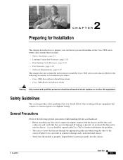
... the following documents for Installation This chapter describes how to prepare your site before inserting it gently into the chassis. Refer to the following general precautions while handling the line card hardware: • Before installing any equipment ... should be allowed to electrical power or telephone wiring. 2 C H A P T E R Preparing for installation procedures: • Cisco 7600 Series Router Installation Guide • Cisco 7609 Router Installation Guide Warning Only trained and qualified personnel should be opened with any line card or supervisor engine, inspect both the...
... the following documents for Installation This chapter describes how to prepare your site before inserting it gently into the chassis. Refer to the following general precautions while handling the line card hardware: • Before installing any equipment ... should be allowed to electrical power or telephone wiring. 2 C H A P T E R Preparing for installation procedures: • Cisco 7600 Series Router Installation Guide • Cisco 7609 Router Installation Guide Warning Only trained and qualified personnel should be opened with any line card or supervisor engine, inspect both the...

Installation Guide
Page 62
...;pi. and they contain electromagnetic interference (EMI) that might disrupt other equipment; they direct the flow of cooling air through the chassis. Het systeem niet bedienen tenzij alle kaarten, vlakplaten en afdekkingen aan de voor- Ceux-ci remplissent trois fonctions essentielles : ils é.... Warnung Blanke Faceplates und Abdeckungen haben drei wichtigen Funktionen: (1) Sie schützen vor gefährlichen Spannungen und Strom innerhalb des Chassis; (2) sie halten elektromagnetische Interferenzen (EMI) zurück, die andere Geräte stören könnten; (3) sie ...
...;pi. and they contain electromagnetic interference (EMI) that might disrupt other equipment; they direct the flow of cooling air through the chassis. Het systeem niet bedienen tenzij alle kaarten, vlakplaten en afdekkingen aan de voor- Ceux-ci remplissent trois fonctions essentielles : ils é.... Warnung Blanke Faceplates und Abdeckungen haben drei wichtigen Funktionen: (1) Sie schützen vor gefährlichen Spannungen und Strom innerhalb des Chassis; (2) sie halten elektromagnetische Interferenzen (EMI) zurück, die andere Geräte stören könnten; (3) sie ...
Installation Guide
Page 79
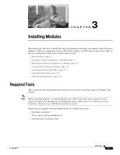
These tools are required to the Cisco 7600 Series Router Installation Guide or Cisco 7609 Router Installation Guide. For information on installing the chassis, refer to install modules in the Cisco 7600 series router, and it contains these sections: • Required Tools, page 3-1 • Installing a ...20 • Verifying the Installation, page 3-22 Required Tools This section describes the requirements and the tools you must install the Cisco 7600 series router chassis and at least one supervisor engine. Installing Modules 3 C H A P T E R This chapter describes how to install...
These tools are required to the Cisco 7600 Series Router Installation Guide or Cisco 7609 Router Installation Guide. For information on installing the chassis, refer to install modules in the Cisco 7600 series router, and it contains these sections: • Required Tools, page 3-1 • Installing a ...20 • Verifying the Installation, page 3-22 Required Tools This section describes the requirements and the tools you must install the Cisco 7600 series router chassis and at least one supervisor engine. Installing Modules 3 C H A P T E R This chapter describes how to install...

Installation Guide
Page 80
Although the metal carrier helps to install a supervisor engine, OSM, or recommended Catalyst 6000 family module in the Cisco 7600 series router. These devices prevent accidental removal, provide proper grounding for the system, and help to ensure that are ...• Place a removed component board-side-up on the body; Electromagnetic interference (EMI) shielding and connectors are improperly handled, results in the chassis depending on clothing can occur when electronic cards or components are integral components of the carrier. Installing a Supervisor Engine or a Module Chapter 3...
Although the metal carrier helps to install a supervisor engine, OSM, or recommended Catalyst 6000 family module in the Cisco 7600 series router. These devices prevent accidental removal, provide proper grounding for the system, and help to ensure that are ...• Place a removed component board-side-up on the body; Electromagnetic interference (EMI) shielding and connectors are improperly handled, results in the chassis depending on clothing can occur when electronic cards or components are integral components of the carrier. Installing a Supervisor Engine or a Module Chapter 3...
Installation Guide
Page 81
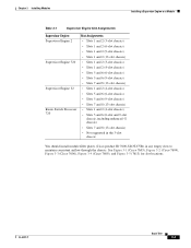
... 3-1 (Cisco 7603), Figure 3-2 (Cisco 7604), Figure 3-3 (Cisco 7606), Figure 3-4 (Cisco 7609), and Figure 3-5 (7613) for slot locations. OL-5077-7 Book Title 3-3 Chapter 3 Installing Modules Installing a Supervisor Engine or a Module Table 3-1 Supervisor Engine Slot Assignments Supervisor Engine Supervisor Engine 2 Supervisor Engine 720 Supervisor Engine 32 Route Switch Processor 720 Slot Assignments • Slots 1 and 2 (3-slot chassis) •...
... 3-1 (Cisco 7603), Figure 3-2 (Cisco 7604), Figure 3-3 (Cisco 7606), Figure 3-4 (Cisco 7609), and Figure 3-5 (7613) for slot locations. OL-5077-7 Book Title 3-3 Chapter 3 Installing Modules Installing a Supervisor Engine or a Module Table 3-1 Supervisor Engine Slot Assignments Supervisor Engine Supervisor Engine 2 Supervisor Engine 720 Supervisor Engine 32 Route Switch Processor 720 Slot Assignments • Slots 1 and 2 (3-slot chassis) •...

Installation Guide
Page 86
... compressed in order to maximize the opening size and making it difficult to install the replacement module. To remove a module, follow the procedure in the chassis (horizontal or vertical), perform one of these two sets of the slots in the "Removing the Supervisor Engine or a Module" section on the installed modules... TX PORT 4 45168 Captive Ejector lever installation screws Step 6 Depending on the position of substeps: Horizontal slot a. Position the supervisor engine or module in the chassis to ensure that contain only module filler plates.
... compressed in order to maximize the opening size and making it difficult to install the replacement module. To remove a module, follow the procedure in the chassis (horizontal or vertical), perform one of these two sets of the slots in the "Removing the Supervisor Engine or a Module" section on the installed modules... TX PORT 4 45168 Captive Ejector lever installation screws Step 6 Depending on the position of substeps: Horizontal slot a. Position the supervisor engine or module in the chassis to ensure that contain only module filler plates.
Installation Guide
Page 92
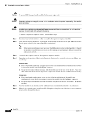
... Horizontal slots a. Step 5 Step 6 Vertical slots a. Place your thumbs on the ejector levers located at the top and bottom of the chassis and to unseat the module from disconnected fibers or connectors. Do not touch the module circuitry. Place the module on the backplane when the ... Place your thumbs on the installed modules will push the modules toward the open slot, reducing the opening size and making it in the chassis (horizontal or vertical), perform one of the module. b. Warning Invisible laser radiation may be emitted from the backplane connector. Do not stare...
... Horizontal slots a. Step 5 Step 6 Vertical slots a. Place your thumbs on the ejector levers located at the top and bottom of the chassis and to unseat the module from disconnected fibers or connectors. Do not touch the module circuitry. Place the module on the backplane when the ... Place your thumbs on the installed modules will push the modules toward the open slot, reducing the opening size and making it in the chassis (horizontal or vertical), perform one of the module. b. Warning Invisible laser radiation may be emitted from the backplane connector. Do not stare...

Installation Guide
Page 93
The console port, located on the front panel of cooling air through the chassis. Connect to the port using the cable and adapters provided, place the console port mode switch in the in position (factory default). they direct... • Connecting a Modem, page 3-16 Note The accessory kit that might disrupt other equipment; and they contain electromagnetic interference (EMI) that shipped with your Cisco 7600 series router contains the necessary cable and adapters to connect a terminal or modem to -DB-9 DTE adapter (labeled "Terminal"). Figure 3-11 Supervisor Engine Console...
The console port, located on the front panel of cooling air through the chassis. Connect to the port using the cable and adapters provided, place the console port mode switch in the in position (factory default). they direct... • Connecting a Modem, page 3-16 Note The accessory kit that might disrupt other equipment; and they contain electromagnetic interference (EMI) that shipped with your Cisco 7600 series router contains the necessary cable and adapters to connect a terminal or modem to -DB-9 DTE adapter (labeled "Terminal"). Figure 3-11 Supervisor Engine Console...

Installation Guide
Page 94
... Supervisor Engine Chapter 3 Installing Modules To connect a terminal using a Catalyst 5000 family Supervisor Engine III console cable, place the console port mode switch in the chassis. To connect to install a patch cord between the GBIC and the MMF cable. Note When you are fully inserted into the GBIC. The baud rate...
... Supervisor Engine Chapter 3 Installing Modules To connect a terminal using a Catalyst 5000 family Supervisor Engine III console cable, place the console port mode switch in the chassis. To connect to install a patch cord between the GBIC and the MMF cable. Note When you are fully inserted into the GBIC. The baud rate...
Installation Guide
Page 103
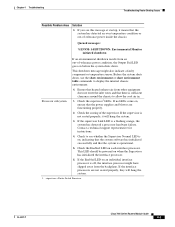
...allow the cool air in. 1. Ensure that heated exhaust air from the backplane. Check to display the internal chassis environment. supervisor = Route Switch Processor OL-5077-7 Cisco 7600 Series Routers Module Guide 4-3 If the supervisor is a flashing orange, the system has detected a processor ...not enter the inlet vents and that the system has detected an over temperature condition or out-of-tolerance power inside the chassis: Queued messages: %ENVM-1-SHUTDOWN: Environmental Monitor initiated shutdown If an environmental shutdown results from an out-of the supervisor. ...
...allow the cool air in. 1. Ensure that heated exhaust air from the backplane. Check to display the internal chassis environment. supervisor = Route Switch Processor OL-5077-7 Cisco 7600 Series Routers Module Guide 4-3 If the supervisor is a flashing orange, the system has detected a processor ...not enter the inlet vents and that the system has detected an over temperature condition or out-of-tolerance power inside the chassis: Queued messages: %ENVM-1-SHUTDOWN: Environmental Monitor initiated shutdown If an environmental shutdown results from an out-of the supervisor. ...
Installation Guide
Page 115
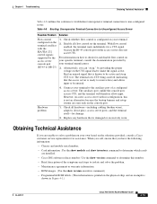
... for a CTS signal because the RJ-45 console port on the terminal. Alternatively, you have the following information: • Chassis and module serial number. • Card information :Use the show module and show inventory command to determine which cards are installed. •...by the access server console port (RJ-45 to be active and strap CTS to determine this is shown in Figure 4-1.) OL-5077-7 Cisco 7600 Series Routers Module Guide 4-15 Table 4-8 Booting: Unresponsive Terminal Connection to Unconfigured Access Server Possible Problem Solution Flow control configured on ...
... for a CTS signal because the RJ-45 console port on the terminal. Alternatively, you have the following information: • Chassis and module serial number. • Card information :Use the show module and show inventory command to determine which cards are installed. •...by the access server console port (RJ-45 to be active and strap CTS to determine this is shown in Figure 4-1.) OL-5077-7 Cisco 7600 Series Routers Module Guide 4-15 Table 4-8 Booting: Unresponsive Terminal Connection to Unconfigured Access Server Possible Problem Solution Flow control configured on ...

Installation Guide
Page 137
... 1-13, 1-14 OL-5077-7 Index SWITCH LOAD meter 1-12 SYSTEM LED 1-12, 1-13, 1-14 PCMCIA slot 1-16 Reset button 1-15 Supervisor Engine 720 chassis slot assignments 3-2 supervisor engine slot assignements (table) 3-3 Switch Fabric Module ACTIVE LED 1-27, 1-28 description 1-27 figure 1-27, 1-28 LCD display 1-27..., 1-28 STATUS LED 1-27, 1-28 switch load meter, description 1-16 SWITCH LOAD meter, supervisor engine 1-12 SX GBIC 1-26 system banner Cisco 7500 series routers 4-3 system images none in Flash memory 4-18 SYSTEM LED, supervisor engine 1-12, 1-13, 1-14 T terminal, connecting to 3-15 ...
... 1-13, 1-14 OL-5077-7 Index SWITCH LOAD meter 1-12 SYSTEM LED 1-12, 1-13, 1-14 PCMCIA slot 1-16 Reset button 1-15 Supervisor Engine 720 chassis slot assignments 3-2 supervisor engine slot assignements (table) 3-3 Switch Fabric Module ACTIVE LED 1-27, 1-28 description 1-27 figure 1-27, 1-28 LCD display 1-27..., 1-28 STATUS LED 1-27, 1-28 switch load meter, description 1-16 SWITCH LOAD meter, supervisor engine 1-12 SX GBIC 1-26 system banner Cisco 7500 series routers 4-3 system images none in Flash memory 4-18 SYSTEM LED, supervisor engine 1-12, 1-13, 1-14 T terminal, connecting to 3-15 ...
