Installation Guide
Page 2
... part of UCB's public domain version of the FCC rules. If the equipment causes interference to radio or television reception, try to provide reasonable protection against such interference in which case users will not occur in accordance with the instruction manual, may be required to correct any other company. (0908R) Cisco ME 6500 Series Ethernet Switch Installation Guide © 2006-2009 Cisco...
... part of UCB's public domain version of the FCC rules. If the equipment causes interference to radio or television reception, try to provide reasonable protection against such interference in which case users will not occur in accordance with the instruction manual, may be required to correct any other company. (0908R) Cisco ME 6500 Series Ethernet Switch Installation Guide © 2006-2009 Cisco...
Installation Guide
Page 18
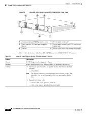
...) 3 Fan tray 4 Power supply status LEDs 5 Power supply terminal block (DC-input power supply only) 6 Power on/off switch (DC-input power supply) Table 1-1 lists the features of the Cisco ME 6524 Ethernet switch (ME-C6524GS-8S) chassis. FAN-C6524 Note The fan tray contains seven individual fans for chassis cooling. you must replace the fan tray. • Fan tray FAN status LED - Red-One or more individual fans have failed. modules cannot be installed in the chassis. • The chassis supports one hot-swappable fan tray. Cisco ME 6500 Series Ethernet Switch Installation Guide...
...) 3 Fan tray 4 Power supply status LEDs 5 Power supply terminal block (DC-input power supply only) 6 Power on/off switch (DC-input power supply) Table 1-1 lists the features of the Cisco ME 6524 Ethernet switch (ME-C6524GS-8S) chassis. FAN-C6524 Note The fan tray contains seven individual fans for chassis cooling. you must replace the fan tray. • Fan tray FAN status LED - Red-One or more individual fans have failed. modules cannot be installed in the chassis. • The chassis supports one hot-swappable fan tray. Cisco ME 6500 Series Ethernet Switch Installation Guide...
Installation Guide
Page 19
...-03 Cisco ME 6500 Series Ethernet Switch Installation Guide 1-3 PWR-400W-AC (400 W AC-input power supply) Note The 400 W AC-input power supply requires single-phase source AC. DWDM-SFP-xxxx-DWDM SFP transceivers • The 24 downlink ports support the following power supplies are supported: - Note Refer to Appendix A for SFP transceiver cabling distances and additional information. Pluggable transceivers supported • The chassis supports SFP transceivers. • The 8 uplink ports support the following SFP transceiver types...
...-03 Cisco ME 6500 Series Ethernet Switch Installation Guide 1-3 PWR-400W-AC (400 W AC-input power supply) Note The 400 W AC-input power supply requires single-phase source AC. DWDM-SFP-xxxx-DWDM SFP transceivers • The 24 downlink ports support the following power supplies are supported: - Note Refer to Appendix A for SFP transceiver cabling distances and additional information. Pluggable transceivers supported • The chassis supports SFP transceivers. • The 8 uplink ports support the following SFP transceiver types...
Installation Guide
Page 20
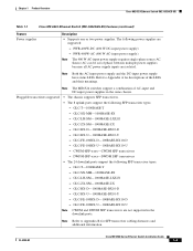
... FAN LED indicates the status of the individual fans in the fan tray. • Green-Fan tray is operating normally. • Red-One or more individual fans in the system. • Amber-System is booting up. • Off-The system is not installed. A recessed switch allows the user to the command-line interface. Cisco ME 6500 Series Ethernet Switch Installation Guide 1-4 OL-8900-03 A single console port allows the user access to reset the system. The console port has...
... FAN LED indicates the status of the individual fans in the fan tray. • Green-Fan tray is operating normally. • Red-One or more individual fans in the system. • Amber-System is booting up. • Off-The system is not installed. A recessed switch allows the user to the command-line interface. Cisco ME 6500 Series Ethernet Switch Installation Guide 1-4 OL-8900-03 A single console port allows the user access to reset the system. The console port has...
Installation Guide
Page 21
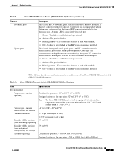
... downlink ports. An SFP transceiver must be installed in the downlink port. Cable type and recommended cabling distance are determined by the type of the Cisco ME 6524 Ethernet switch (ME-C6524GS-8S) chassis. Cable type and recommended cabling distance are determined by the type of SFP transceiver installed in the port socket for operation: 32° to 130°F (0° to 3000 m) OL-8900-03 Cisco ME 6500 Series Ethernet Switch Installation Guide 1-5 Table 1-2 Cisco ME 6524 Ethernet Switch (ME-C6524GS-8S) Specifications...
... downlink ports. An SFP transceiver must be installed in the downlink port. Cable type and recommended cabling distance are determined by the type of the Cisco ME 6524 Ethernet switch (ME-C6524GS-8S) chassis. Cable type and recommended cabling distance are determined by the type of SFP transceiver installed in the port socket for operation: 32° to 130°F (0° to 3000 m) OL-8900-03 Cisco ME 6500 Series Ethernet Switch Installation Guide 1-5 Table 1-2 Cisco ME 6524 Ethernet Switch (ME-C6524GS-8S) Specifications...
Installation Guide
Page 24
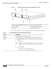
... installed in the chassis. • The chassis supports one hot-swappable fan tray. The individual fans are not field replaceable; Cisco ME 6524 Ethernet Switch (ME-C6524GT-8S) Chapter 1 Product Overview Figure 1-4 6 Cisco ME 6524 Ethernet Switch (ME-C6524GT-8S)-Rear View 5 4 Table 1-3 Feature Chassis Modules Fan tray 147978 1 o + - OUTPUT OK INPUT OK FAN OK 2 3 1 System ground pad/NEBS ground location 2 Power supplies 3 Fan tray 4 Power supply status LEDs 5 Power supply terminal block 6 Power on/off switch Table 1-3 lists the features of the Cisco ME 6524 Ethernet switch...
... installed in the chassis. • The chassis supports one hot-swappable fan tray. The individual fans are not field replaceable; Cisco ME 6524 Ethernet Switch (ME-C6524GT-8S) Chapter 1 Product Overview Figure 1-4 6 Cisco ME 6524 Ethernet Switch (ME-C6524GT-8S)-Rear View 5 4 Table 1-3 Feature Chassis Modules Fan tray 147978 1 o + - OUTPUT OK INPUT OK FAN OK 2 3 1 System ground pad/NEBS ground location 2 Power supplies 3 Fan tray 4 Power supply status LEDs 5 Power supply terminal block 6 Power on/off switch Table 1-3 lists the features of the Cisco ME 6524 Ethernet switch...

Installation Guide
Page 26
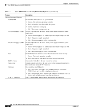
...-The power supply is off or is not installed. The FAN LED indicates the status of the power supply installed in the fan tray have failed. A recessed switch allows the user to the command-line interface. Type 2 CompactFlash devices can plug into this port. The switch has two USB ports: • Port 1 is a host port with a Type B USB connector. A standard USB 1.1 host, such as flash memory, can plug into this connector. 1-10 Cisco ME 6500 Series Ethernet Switch Installation Guide OL...
...-The power supply is off or is not installed. The FAN LED indicates the status of the power supply installed in the fan tray have failed. A recessed switch allows the user to the command-line interface. Type 2 CompactFlash devices can plug into this port. The switch has two USB ports: • Port 1 is a host port with a Type B USB connector. A standard USB 1.1 host, such as flash memory, can plug into this connector. 1-10 Cisco ME 6500 Series Ethernet Switch Installation Guide OL...

Installation Guide
Page 27
... Overview Cisco ME 6524 Ethernet Switch (ME-C6524GT-8S) Table 1-3 Cisco ME 6524 Ethernet Switch (ME-C6524GT-8S) Features (continued) Feature Downlink ports Uplink ports Description The chassis has 24 10/100/1000BASE downlink ports. A status LED is associated with each port. • Green-The link is established and operational. • Amber-The port is disabled. • Blinking amber-The system has detected a fault with the link. • Off-No link is established or no network interface cable...
... Overview Cisco ME 6524 Ethernet Switch (ME-C6524GT-8S) Table 1-3 Cisco ME 6524 Ethernet Switch (ME-C6524GT-8S) Features (continued) Feature Downlink ports Uplink ports Description The chassis has 24 10/100/1000BASE downlink ports. A status LED is associated with each port. • Green-The link is established and operational. • Amber-The port is disabled. • Blinking amber-The system has detected a fault with the link. • Off-No link is established or no network interface cable...

Installation Guide
Page 38
... local electrical codes and restrictions. • Ensure that the DC return remains isolated from the system frame and the chassis (DC-I). 2-10 Cisco ME 6500 Series Ethernet Switch Installation Guide OL-8900-03 The wire gauge size and connector size is within the current ratings of the wiring and breakers. • You can connect the DC-input power supply to the power source...
... local electrical codes and restrictions. • Ensure that the DC return remains isolated from the system frame and the chassis (DC-I). 2-10 Cisco ME 6500 Series Ethernet Switch Installation Guide OL-8900-03 The wire gauge size and connector size is within the current ratings of the wiring and breakers. • You can connect the DC-input power supply to the power source...

Installation Guide
Page 45
... L brackets on the rear sides of the chassis. OUTPUT OK INPUT OK FAN OK Rear-mounting position M4 Phillips flat-head screws 147979 OL-8900-03 Cisco ME 6500 Series Ethernet Switch Installation Guide 3-5 the right-side L bracket (as viewed from the front of the chassis) has the part number 700-20932-xx. Chapter 3 Installing the Switch Rack-Mounting Attaching L Brackets to identify them as left -side...
... L brackets on the rear sides of the chassis. OUTPUT OK INPUT OK FAN OK Rear-mounting position M4 Phillips flat-head screws 147979 OL-8900-03 Cisco ME 6500 Series Ethernet Switch Installation Guide 3-5 the right-side L bracket (as viewed from the front of the chassis) has the part number 700-20932-xx. Chapter 3 Installing the Switch Rack-Mounting Attaching L Brackets to identify them as left -side...

Installation Guide
Page 49
...-8900-03 Cisco ME 6500 Series Ethernet Switch Installation Guide 3-9 Verify that there is securely attached to the ground lug. Secure the grounding lug to the chassis with two M4 screws. (See Figure 3-4.) Ensure that the grounding lug and the grounding wire do not interfere with other end of the grounding wire, and connect it to an appropriate grounding point in...
...-8900-03 Cisco ME 6500 Series Ethernet Switch Installation Guide 3-9 Verify that there is securely attached to the ground lug. Secure the grounding lug to the chassis with two M4 screws. (See Figure 3-4.) Ensure that the grounding lug and the grounding wire do not interfere with other end of the grounding wire, and connect it to an appropriate grounding point in...

Installation Guide
Page 50
... power source should still be used on the power supply are tight. Verify that you are connecting. The maximum width of the source DC cable connections are secure, reinstall the plastic terminal block cover. Use only copper wire. Positive (+) source DC cable to the positive (+) connector on the terminal block 3. Connecting Source Power to the Chassis Chapter 3 Installing the Switch Connecting Source DC to the DC-Input Power Supply To connect...
... power source should still be used on the power supply are tight. Verify that you are connecting. The maximum width of the source DC cable connections are secure, reinstall the plastic terminal block cover. Use only copper wire. Positive (+) source DC cable to the positive (+) connector on the terminal block 3. Connecting Source Power to the Chassis Chapter 3 Installing the Switch Connecting Source DC to the DC-Input Power Supply To connect...

Installation Guide
Page 51
... kit that shipped with your Cisco ME 6524 Ethernet switch contains a cable to connect a terminal or modem to the console port from the CLI. • Monitor network statistics and errors. • Configure SNMP agent parameters. • Download software updates to the switch or distribute software images that reside in flash memory to the AC-input power supply, follow these steps: Step 1 Step 2 Step 3 Step 4 Verify that the power switch is shown in the cable. The console port...
... kit that shipped with your Cisco ME 6524 Ethernet switch contains a cable to connect a terminal or modem to the console port from the CLI. • Monitor network statistics and errors. • Configure SNMP agent parameters. • Download software updates to the switch or distribute software images that reside in flash memory to the AC-input power supply, follow these steps: Step 1 Step 2 Step 3 Step 4 Verify that the power switch is shown in the cable. The console port...

Installation Guide
Page 52
... clasp 130927 3-12 Cisco ME 6500 Series Ethernet Switch Installation Guide OL-8900-03 Caution We strongly recommend that is absolutely necessary. Installing the SFP Transceivers Chapter 3 Installing the Switch Step 4 Check the terminal documentation to the cables, the cable connector, or the optical interfaces in the SFP transceiver. The baud rate of the terminal must not exceed the stipulated cable length for the switch. SFP transceivers are inserted into...
... clasp 130927 3-12 Cisco ME 6500 Series Ethernet Switch Installation Guide OL-8900-03 Caution We strongly recommend that is absolutely necessary. Installing the SFP Transceivers Chapter 3 Installing the Switch Step 4 Check the terminal documentation to the cables, the cable connector, or the optical interfaces in the SFP transceiver. The baud rate of the terminal must not exceed the stipulated cable length for the switch. SFP transceivers are inserted into...

Installation Guide
Page 55
... need further configuration. During the power-up the system. See the Cisco ME 6500 Series Ethernet Switch Software Configuration Guide and the Cisco ME 6500 Series Ethernet Switch Cisco IOS Command Reference on Cisco.com for information on using the CLI with a Cisco ME 6524 Ethernet switch. Chapter 3 Installing the Switch Powering Up the Chassis Powering Up the Chassis Turn on the power supply switches to Go Next If the default configuration is running. OL-8900-03 Cisco ME 6500 Series Ethernet Switch Installation Guide 3-15 Additional system diagnostic tests are available...
... need further configuration. During the power-up the system. See the Cisco ME 6500 Series Ethernet Switch Software Configuration Guide and the Cisco ME 6500 Series Ethernet Switch Cisco IOS Command Reference on Cisco.com for information on using the CLI with a Cisco ME 6524 Ethernet switch. Chapter 3 Installing the Switch Powering Up the Chassis Powering Up the Chassis Turn on the power supply switches to Go Next If the default configuration is running. OL-8900-03 Cisco ME 6500 Series Ethernet Switch Installation Guide 3-15 Additional system diagnostic tests are available...

Installation Guide
Page 58
... block in Figure 4-1 (bottom view), and slide the power supply completely out of the following procedures, ensure that you will need a Number 2 Phillips screwdriver. Grasp the power supply handle with one hand, and slide the power supply halfway out of the power supply bay, be made first and disconnected last. Cisco ME 6500 Series Ethernet Switch Installation Guide 4-2 OL-8900-03 Turn OFF the DC power line circuit breakers and remove...
... block in Figure 4-1 (bottom view), and slide the power supply completely out of the following procedures, ensure that you will need a Number 2 Phillips screwdriver. Grasp the power supply handle with one hand, and slide the power supply halfway out of the power supply bay, be made first and disconnected last. Cisco ME 6500 Series Ethernet Switch Installation Guide 4-2 OL-8900-03 Turn OFF the DC power line circuit breakers and remove...

Installation Guide
Page 60
.... Cisco ME 6500 Series Ethernet Switch Installation Guide 4-4 OL-8900-03 Verify that the power switch is off (0) position on the power supply that you are working on the front edge) of the power supply. Either insulated crimp-on spade lugs or insulated crimp-on ring connectors can be used on the DC power lines that service the DC circuits. Remove the new DC-input power supply from the terminal block. Remove...
.... Cisco ME 6500 Series Ethernet Switch Installation Guide 4-4 OL-8900-03 Verify that the power switch is off (0) position on the power supply that you are working on the front edge) of the power supply. Either insulated crimp-on spade lugs or insulated crimp-on ring connectors can be used on the DC power lines that service the DC circuits. Remove the new DC-input power supply from the terminal block. Remove...

Installation Guide
Page 83
... 6500 Series Ethernet Switch Installation Guide B-5 Note DWDM SFP transceivers are supported on label C WCDl aMLsN-sSS#F15/ N0P2:-171OC/40HF711R021-3203G4405. 1003 6 - 1 3 Dustplug Receive optical bore Transmit optical bore Bail clasp 113753 DWDM SFP transceivers are 32 fixed-wavelength DWDM SFPs that support the International Telecommunications Union (ITU) 100-GHz wavelength grid. Note Only connections using APC connectors are supported. Appendix B SFP Transceiver Specifications...
... 6500 Series Ethernet Switch Installation Guide B-5 Note DWDM SFP transceivers are supported on label C WCDl aMLsN-sSS#F15/ N0P2:-171OC/40HF711R021-3203G4405. 1003 6 - 1 3 Dustplug Receive optical bore Transmit optical bore Bail clasp 113753 DWDM SFP transceivers are 32 fixed-wavelength DWDM SFPs that support the International Telecommunications Union (ITU) 100-GHz wavelength grid. Note Only connections using APC connectors are supported. Appendix B SFP Transceiver Specifications...
Installation Guide
Page 86
..., chassis ME-C6524GS-8S Ethernet switches 1-6 ME-C6524GT-8S Ethernet switches 1-12 documentation audience i-vii conventions i-viii organization i-vii related i-xiv downlink port LEDs 1-11 DWDM SFP transceivers description B-5 product numbers and ITU channel numbers B-5 E environmental specifications Catalyst 6503 switches 1-5 ME-C6524GT-8S Ethernet switches 1-11 ESD guidelines 2-7 preventing 2-7 F fan assemblies fan status LED 2-4 installing 4-9 FAN LED 1-10 fan tray removal and replacement procedure 4-8 required tools 4-8 IN-2 Cisco ME 6500 Series Ethernet Switch Installation Guide...
..., chassis ME-C6524GS-8S Ethernet switches 1-6 ME-C6524GT-8S Ethernet switches 1-12 documentation audience i-vii conventions i-viii organization i-vii related i-xiv downlink port LEDs 1-11 DWDM SFP transceivers description B-5 product numbers and ITU channel numbers B-5 E environmental specifications Catalyst 6503 switches 1-5 ME-C6524GT-8S Ethernet switches 1-11 ESD guidelines 2-7 preventing 2-7 F fan assemblies fan status LED 2-4 installing 4-9 FAN LED 1-10 fan tray removal and replacement procedure 4-8 required tools 4-8 IN-2 Cisco ME 6500 Series Ethernet Switch Installation Guide...
Installation Guide
Page 87
...related documentation xiv removal and replacement procedures AC-input power supplies 4-6 DC-input power supplies 4-1, 4-2 fan tray 4-8 memory upgrade procedure 4-10 rubber feet, installation 3-7 S selecting a UPS 2-10 SFP transceivers fiber loss budgets (table) B-3 installing 3-12 major features (figure) B-1 physical and environmental specifications table B-4 supported types B-1 shock and vibration specifications ME-C6524GS-8S Ethernet switches 1-6 ME-C6524GT-8S Ethernet switches 1-12 signaling and pinouts terminal setup 3-12 OL-8900-03 Cisco ME 6500 Series Ethernet Switch Installation Guide...
...related documentation xiv removal and replacement procedures AC-input power supplies 4-6 DC-input power supplies 4-1, 4-2 fan tray 4-8 memory upgrade procedure 4-10 rubber feet, installation 3-7 S selecting a UPS 2-10 SFP transceivers fiber loss budgets (table) B-3 installing 3-12 major features (figure) B-1 physical and environmental specifications table B-4 supported types B-1 shock and vibration specifications ME-C6524GS-8S Ethernet switches 1-6 ME-C6524GT-8S Ethernet switches 1-12 signaling and pinouts terminal setup 3-12 OL-8900-03 Cisco ME 6500 Series Ethernet Switch Installation Guide...


