
Hardware Installation Guide
Page 1
Cisco IE 3010 Switch Hardware Installation Guide August 2011 Americas Headquarters Cisco Systems, Inc. 170 West Tasman Drive San Jose, CA 95134-1706 USA http://www.cisco.com Tel: 408 526-4000 800 553-NETS (6387) Fax: 408 527-0883 Text Part Number: 78-19581-01
Cisco IE 3010 Switch Hardware Installation Guide August 2011 Americas Headquarters Cisco Systems, Inc. 170 West Tasman Drive San Jose, CA 95134-1706 USA http://www.cisco.com Tel: 408 526-4000 800 553-NETS (6387) Fax: 408 527-0883 Text Part Number: 78-19581-01

Hardware Installation Guide
Page 2
... on , users are encouraged to try to radio communications. Cisco IE 3010 Switch Hardware Installation Guide © 2010-2011 Cisco Systems, Inc. However, there is likely to part 15 of their own expense. The Cisco implementation of Cisco's trademarks can be actual addresses. All rights reserved. A...equipment in a commercial environment. Modifications to radio or television reception, which the receiver is for illustrative purposes only. Cisco and the Cisco Logo are the property of the FCC rules. USERS MUST TAKE FULL RESPONSIBILITY FOR THEIR APPLICATION OF ANY PRODUCTS. ...
... on , users are encouraged to try to radio communications. Cisco IE 3010 Switch Hardware Installation Guide © 2010-2011 Cisco Systems, Inc. However, there is likely to part 15 of their own expense. The Cisco implementation of Cisco's trademarks can be actual addresses. All rights reserved. A...equipment in a commercial environment. Modifications to radio or television reception, which the receiver is for illustrative purposes only. Cisco and the Cisco Logo are the property of the FCC rules. USERS MUST TAKE FULL RESPONSIBILITY FOR THEIR APPLICATION OF ANY PRODUCTS. ...

Hardware Installation Guide
Page 3
... Ethernet Ports 1-3 PoE Ports 1-3 Dual-Purpose Ports 1-4 SFP Modules 1-5 SFP Module Patch Cable 1-6 Power-Input Terminal 1-6 Alarm Ports 1-6 Alarm Input 1-7 Alarm Output 1-7 Management Ports 1-7 LEDs 1-8 Switch Panel LEDs 1-8 System LED 1-9 Power-Supply Module LEDs 1-9 Alarm LEDs 1-9 Console LEDs 1-10 Port LEDs 1-10 PoE LED 1-11 Dual-Purpose Port LEDs 1-11 SD... Memory Card 1-11 Power-Supply Side 1-12 Power-Supply Side LEDs 1-13 Power Supply Features 1-14 Management Options 1-14 Network Configurations 1-14 78-19581-01 Cisco IE 3010 Switch Hardware Installation Guide iii
... Ethernet Ports 1-3 PoE Ports 1-3 Dual-Purpose Ports 1-4 SFP Modules 1-5 SFP Module Patch Cable 1-6 Power-Input Terminal 1-6 Alarm Ports 1-6 Alarm Input 1-7 Alarm Output 1-7 Management Ports 1-7 LEDs 1-8 Switch Panel LEDs 1-8 System LED 1-9 Power-Supply Module LEDs 1-9 Alarm LEDs 1-9 Console LEDs 1-10 Port LEDs 1-10 PoE LED 1-11 Dual-Purpose Port LEDs 1-11 SD... Memory Card 1-11 Power-Supply Side 1-12 Power-Supply Side LEDs 1-13 Power Supply Features 1-14 Management Options 1-14 Network Configurations 1-14 78-19581-01 Cisco IE 3010 Switch Hardware Installation Guide iii

Hardware Installation Guide
Page 4
...Switch Operation 2-3 Installing the Switch 2-4 Rack-Mounting 2-4 Attaching Brackets for 19-Inch Racks 2-5 Attaching Brackets for 19-Inch Racks (IP-30 Compliance) 2-6 Attaching Brackets for 23-Inch Racks 2-12 Attaching Brackets for ETSI Racks 2-13 Rack Mounting 2-14 Wall-Mounting 2-15 Attaching Brackets 2-16... Guidelines 3-3 Installing a Power-Supply Module 3-4 Equipment That You Need 3-4 Grounding the Switch 3-5 Installing the Power-Supply Module in the Switch 3-7 Wiring the Power Source 3-8 Removing the Power-Supply Module 3-13 Cisco IE 3010 Switch Hardware Installation Guide iv 78-19581-01
...Switch Operation 2-3 Installing the Switch 2-4 Rack-Mounting 2-4 Attaching Brackets for 19-Inch Racks 2-5 Attaching Brackets for 19-Inch Racks (IP-30 Compliance) 2-6 Attaching Brackets for 23-Inch Racks 2-12 Attaching Brackets for ETSI Racks 2-13 Rack Mounting 2-14 Wall-Mounting 2-15 Attaching Brackets 2-16... Guidelines 3-3 Installing a Power-Supply Module 3-4 Equipment That You Need 3-4 Grounding the Switch 3-5 Installing the Power-Supply Module in the Switch 3-7 Wiring the Power Source 3-8 Removing the Power-Supply Module 3-13 Cisco IE 3010 Switch Hardware Installation Guide iv 78-19581-01

Hardware Installation Guide
Page 5
... Default Settings 4-5 Finding the Switch Serial Number 4-5 Technical Specifications A-1 Switch Specifications A-1 Power-Supply Module Specifications A-4 Alarm Ratings A-5 Connector and Cable Specifications B-1 Connector Specifications B-1 10/100 B-1 SFP Module Connectors B-2 Dual-Purpose Ports B-3 Alarm Port B-3 Cables and Adapters B-4 SFP Module Cables B-4 Cable Pinouts B-6 Console Port Adapter Pinouts B-7 Contents 78-19581-01 Cisco IE 3010 Switch Hardware Installation Guide v
... Default Settings 4-5 Finding the Switch Serial Number 4-5 Technical Specifications A-1 Switch Specifications A-1 Power-Supply Module Specifications A-4 Alarm Ratings A-5 Connector and Cable Specifications B-1 Connector Specifications B-1 10/100 B-1 SFP Module Connectors B-2 Dual-Purpose Ports B-3 Alarm Port B-3 Cables and Adapters B-4 SFP Module Cables B-4 Cable Pinouts B-6 Console Port Adapter Pinouts B-7 Contents 78-19581-01 Cisco IE 3010 Switch Hardware Installation Guide v

Hardware Installation Guide
Page 7
...of the Cisco Industrial Ethernet (IE) 3010 switch. In this situation, you might receive or how to configure your switch. Statement 1071 SAVE THESE INSTRUCTIONS 78-19581-01 Cisco IE 3010 Switch Hardware Installation Guide vii See the switch software configuration guide, the switch command reference, and the switch system ... in the translated safety warnings that you work on Cisco.com: http://www.cisco.com/go/IE3010_docs Note Means reader take note. Preface This guide describes the hardware features of the switch, explains how to install it, and provides troubleshooting ...
...of the Cisco Industrial Ethernet (IE) 3010 switch. In this situation, you might receive or how to configure your switch. Statement 1071 SAVE THESE INSTRUCTIONS 78-19581-01 Cisco IE 3010 Switch Hardware Installation Guide vii See the switch software configuration guide, the switch command reference, and the switch system ... in the translated safety warnings that you work on Cisco.com: http://www.cisco.com/go/IE3010_docs Note Means reader take note. Preface This guide describes the hardware features of the switch, explains how to install it, and provides troubleshooting ...
Hardware Installation Guide
Page 8
... the Cisco IE 3010 Switch • Cisco IE 3010 Switch Getting Started Guide • Regulatory Compliance and Safety Information for the Cisco IE 3010 Switch that guide. Cisco IE 3010 Switch Hardware Installation Guide viii 78-19581-01 Related Publications Preface The safety warnings for this product are translated into several languages in the Regulatory Compliance and Safety Information for the Cisco IE 3010 Switch • Cisco IE 3010 Switch Software Configuration Guide • Cisco IE 3010 Switch...
... the Cisco IE 3010 Switch • Cisco IE 3010 Switch Getting Started Guide • Regulatory Compliance and Safety Information for the Cisco IE 3010 Switch that guide. Cisco IE 3010 Switch Hardware Installation Guide viii 78-19581-01 Related Publications Preface The safety warnings for this product are translated into several languages in the Regulatory Compliance and Safety Information for the Cisco IE 3010 Switch • Cisco IE 3010 Switch Software Configuration Guide • Cisco IE 3010 Switch...
Hardware Installation Guide
Page 9
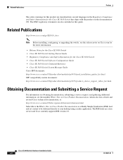
...), human-machine interfaces (HMIs), drives, sensors, and input and output (IO) devices. • Switch Models, page 1-1 • Cable Side, page 1-2 • Power-Supply Side, page 1-12 • Management Options, page 1-14 Switch Models Table 1-1 Switch Models Model Description Cisco IE-3010-24TC Cisco IE-3010-16S-8PC 24 10/100 FastEthernet ports, 2 dual-purpose ports (2 10/100/1000BASE-T copper ports and...
...), human-machine interfaces (HMIs), drives, sensors, and input and output (IO) devices. • Switch Models, page 1-1 • Cable Side, page 1-2 • Power-Supply Side, page 1-12 • Management Options, page 1-14 Switch Models Table 1-1 Switch Models Model Description Cisco IE-3010-24TC Cisco IE-3010-16S-8PC 24 10/100 FastEthernet ports, 2 dual-purpose ports (2 10/100/1000BASE-T copper ports and...

Hardware Installation Guide
Page 10
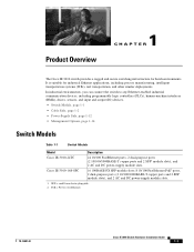
...SD = Secure Digital 6 RJ-45 console port 7 USB (mini-Type B) console port 8 Power-input terminal 9 Alarm port Cisco IE 3010 Switch Hardware Installation Guide 1-2 78-19581-01 Cable Side Chapter 1 Product Overview Cable Side The 10/100 Fast Ethernet downlink ports in ...is above port 4, and so on the left. The dual-purpose ports are grouped in Figure 1-1 are numbered 1 and 2. Figure 1-1 13 Cisco IE-3010-24TC Cable-Side View 5 67 8 208362 C isco IE 3010 2 4 9 1 SD1 flash memory card slot 2 LEDs 3 Express Setup button 4 10/100 ports 5 Dual purpose ports 1. The first member...
...SD = Secure Digital 6 RJ-45 console port 7 USB (mini-Type B) console port 8 Power-input terminal 9 Alarm port Cisco IE 3010 Switch Hardware Installation Guide 1-2 78-19581-01 Cable Side Chapter 1 Product Overview Cable Side The 10/100 Fast Ethernet downlink ports in ...is above port 4, and so on the left. The dual-purpose ports are grouped in Figure 1-1 are numbered 1 and 2. Figure 1-1 13 Cisco IE-3010-24TC Cable-Side View 5 67 8 208362 C isco IE 3010 2 4 9 1 SD1 flash memory card slot 2 LEDs 3 Express Setup button 4 10/100 ports 5 Dual purpose ports 1. The first member...
Hardware Installation Guide
Page 11
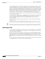
... default setting is above port 4, and so on the switch to operate in pairs. Statement 1072 78-19581-01 Cisco IE 3010 Switch Hardware Installation Guide 1-3 The dual-purpose ports are grouped in any combination of the attached device and advertises its own capabilities. Figure 1-2 13 Cisco IE-3010-16S-8PC Cable-Side View 5 6 78 9 208363 PO W ER OVER ETHERNET...
... default setting is above port 4, and so on the switch to operate in pairs. Statement 1072 78-19581-01 Cisco IE 3010 Switch Hardware Installation Guide 1-3 The dual-purpose ports are grouped in any combination of the attached device and advertises its own capabilities. Figure 1-2 13 Cisco IE-3010-16S-8PC Cable-Side View 5 6 78 9 208363 PO W ER OVER ETHERNET...
Hardware Installation Guide
Page 12
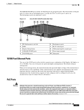
... For information about configuring and monitoring PoE ports, see the switch software configuration guide on Cisco.com. Cisco IE 3010 Switch Hardware Installation Guide 1-4 78-19581-01 For information about port connections and port specifications, see the switch software configuration guide. When a link is achieved on one...Side Chapter 1 Product Overview The 10/100 PoE ports on the Cisco IE-3010-16S-8PC switches provide PoE support for devices that are compliant with the selected media type. The PoE ports on the switch as either 10/100/1000 ports or as low priority PoE ports....
... For information about configuring and monitoring PoE ports, see the switch software configuration guide on Cisco.com. Cisco IE 3010 Switch Hardware Installation Guide 1-4 78-19581-01 For information about port connections and port specifications, see the switch software configuration guide. When a link is achieved on one...Side Chapter 1 Product Overview The 10/100 PoE ports on the Cisco IE-3010-16S-8PC switches provide PoE support for devices that are compliant with the selected media type. The PoE ports on the switch as either 10/100/1000 ports or as low priority PoE ports....

Hardware Installation Guide
Page 13
... your SFP module documentation and the "Installing and Removing SFP Modules" section on page 2-20. Chapter 1 Product Overview Cable Side SFP Modules The switch Ethernet SFP modules provide connections to 60°C) Model • GLC-SX-MM-RGD • GLC-LX-SM-RGD • GLC-FE-100LX...with DOM support • GLC-EX-SMD with DOM support For information about SFP modules, see Appendix B, "SFP Module Cables." 78-19581-01 Cisco IE 3010 Switch Hardware Installation Guide 1-5 You can use any combination of SFP Module Rugged and Industrial SFPs -40 to 140°F (-40 to 60°C) ...
... your SFP module documentation and the "Installing and Removing SFP Modules" section on page 2-20. Chapter 1 Product Overview Cable Side SFP Modules The switch Ethernet SFP modules provide connections to 60°C) Model • GLC-SX-MM-RGD • GLC-LX-SM-RGD • GLC-FE-100LX...with DOM support • GLC-EX-SMD with DOM support For information about SFP modules, see Appendix B, "SFP Module Cables." 78-19581-01 Cisco IE 3010 Switch Hardware Installation Guide 1-5 You can use any combination of SFP Module Rugged and Industrial SFPs -40 to 140°F (-40 to 60°C) ...

Hardware Installation Guide
Page 14
...normally closed . • Open means that no current flows through the contact (referred to power the switch. Cable Side Chapter 1 Product Overview SFP Module Patch Cable The switch uses an SFP-module patch cable, a 0.5-meter, copper, passive cable with one or two power ... 208415 Alarm Ports The switch has four alarm inputs and one of the power sources fail, the other continues to as a normally open or closed contact). The patch cable connects two switches in a cascaded configuration. If one alarm output. Cisco IE 3010 Switch Hardware Installation Guide 1-6 ...
...normally closed . • Open means that no current flows through the contact (referred to power the switch. Cable Side Chapter 1 Product Overview SFP Module Patch Cable The switch uses an SFP-module patch cable, a 0.5-meter, copper, passive cable with one or two power ... 208415 Alarm Ports The switch has four alarm inputs and one of the power sources fail, the other continues to as a normally open or closed contact). The patch cable connects two switches in a cascaded configuration. If one alarm output. Cisco IE 3010 Switch Hardware Installation Guide 1-6 ...
Hardware Installation Guide
Page 15
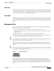
...8226; RJ-45 console port. An alarm generates a system message and turns on the alarm pinouts. Note For information about downloading the Cisco USB device driver, see the switch software guide. They are the same as a door, a temperature gauge, or a fire alarm, to a timeout, you connect two... console port is a dry-contact alarm port. To use the CLI to set the alarm severity to minor, major, or critical. Cisco IE 3010 Switch Hardware Installation Guide 1-7 To connect an external alarm device to the relay, you can connect up to four alarm inputs from the console...
...8226; RJ-45 console port. An alarm generates a system message and turns on the alarm pinouts. Note For information about downloading the Cisco USB device driver, see the switch software guide. They are the same as a door, a temperature gauge, or a fire alarm, to a timeout, you connect two... console port is a dry-contact alarm port. To use the CLI to set the alarm severity to minor, major, or critical. Cisco IE 3010 Switch Hardware Installation Guide 1-7 To connect an external alarm device to the relay, you can connect up to four alarm inputs from the console...
Hardware Installation Guide
Page 16
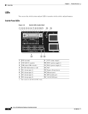
Only on the Cisco IE-3010-16S-8PC switch. 9 OUT (alarm output) 10 PSU1 (power supply 1) 11 PSU2 (power supply 2) 12 PoE1 13 Express Setup button 14 Ethernet ports 15 SFP module port 16 10/100/1000 port Cisco IE 3010 Switch Hardware Installation Guide 1-8 78-19581-01 Switch Panel LEDs Figure 1-6 Switch LEDs (Cable Side) 1 2 3 4 5 6 7 8 9 10 11 12 13 207198 14 15 16 1 SYS...
Only on the Cisco IE-3010-16S-8PC switch. 9 OUT (alarm output) 10 PSU1 (power supply 1) 11 PSU2 (power supply 2) 12 PoE1 13 Express Setup button 14 Ethernet ports 15 SFP module port 16 10/100/1000 port Cisco IE 3010 Switch Hardware Installation Guide 1-8 78-19581-01 Switch Panel LEDs Figure 1-6 Switch LEDs (Cable Side) 1 2 3 4 5 6 7 8 9 10 11 12 13 207198 14 15 16 1 SYS...

Hardware Installation Guide
Page 17
... within the operating range. POST = power-on . They show whether power-supply modules 1 and 2 are labeled PSU1 and PSU2 (on the switch) and PSU OK (on the power-supply module). Valid input is present, and the output is not present. Alarm LEDs Table 1-5 Alarm Input...Minor alarm Major alarm Critical alarm Table 1-6 Color Green Red Alarm Output LED System Status No alarm Relay closed, alarm present 78-19581-01 Cisco IE 3010 Switch Hardware Installation Guide 1-9 See Figure 1-6 and Figure 1-9. Blinking green POST1 is operating normally. Green System is in progress. Amber System is ...
... within the operating range. POST = power-on . They show whether power-supply modules 1 and 2 are labeled PSU1 and PSU2 (on the switch) and PSU OK (on the power-supply module). Valid input is present, and the output is not present. Alarm LEDs Table 1-5 Alarm Input...Minor alarm Major alarm Critical alarm Table 1-6 Color Green Red Alarm Output LED System Status No alarm Relay closed, alarm present 78-19581-01 Cisco IE 3010 Switch Hardware Installation Guide 1-9 See Figure 1-6 and Figure 1-9. Blinking green POST1 is operating normally. Green System is in progress. Amber System is ...

Hardware Installation Guide
Page 18
...console cables, the USB console port has priority. If you connect a cable to 30 seconds as a group or individually, provide information about the switch and about the individual ports. RJ-45 console port is not active. Port LEDs, as STP searches for console communication. After a port is ... Description RJ-45 console port is active. USB console port LED is amber for up to a console port, the switch automatically uses that port for loops. 1-10 Cisco IE 3010 Switch Hardware Installation Guide 78-19581-01 USB console port is active. USB console port is not active. RJ-45 console...
...console cables, the USB console port has priority. If you connect a cable to 30 seconds as a group or individually, provide information about the switch and about the individual ports. RJ-45 console port is not active. Port LEDs, as STP searches for console communication. After a port is ... Description RJ-45 console port is active. USB console port LED is amber for up to a console port, the switch automatically uses that port for loops. 1-10 Cisco IE 3010 Switch Hardware Installation Guide 78-19581-01 USB console port is active. USB console port is not active. RJ-45 console...

Hardware Installation Guide
Page 19
Ports are functioning correctly. The ports can autonegotiate, or you want to reconfigure the new switch. SD flash memory card is functioning. The switch stores the Cisco IOS software images and the switch configuration on page 2-20 for LED descriptions. See the "Installing and Removing SFP Modules" ...identify the connection as either a copper-based connector or an SFP module. See Table 1-8 for information. 78-19581-01 Cisco IE 3010 Switch Hardware Installation Guide 1-11 Cisco IOS boot image cannot be found. PoE is enabled, but not as an SFP-module port, but an error is...
Ports are functioning correctly. The ports can autonegotiate, or you want to reconfigure the new switch. SD flash memory card is functioning. The switch stores the Cisco IOS software images and the switch configuration on page 2-20 for LED descriptions. See the "Installing and Removing SFP Modules" ...identify the connection as either a copper-based connector or an SFP module. See Table 1-8 for information. 78-19581-01 Cisco IE 3010 Switch Hardware Installation Guide 1-11 Cisco IOS boot image cannot be found. PoE is enabled, but not as an SFP-module port, but an error is...

Hardware Installation Guide
Page 20
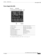
... Both Power-Supply Modules P W R-R G D -LO W -D C P W R-R G D -LO W -D C 208375 CSwisictcohIES3e0ri1e0s 1 1 1 PSU OK LED For a description of the PSU OK LED, see Table 1-4 on page 1-9. 1-12 Cisco IE 3010 Switch Hardware Installation Guide 78-19581-01 Power-Supply Side Chapter 1 Product Overview Power-Supply Side The power-supply side has the LED panel and two ...
... Both Power-Supply Modules P W R-R G D -LO W -D C P W R-R G D -LO W -D C 208375 CSwisictcohIES3e0ri1e0s 1 1 1 PSU OK LED For a description of the PSU OK LED, see Table 1-4 on page 1-9. 1-12 Cisco IE 3010 Switch Hardware Installation Guide 78-19581-01 Power-Supply Side Chapter 1 Product Overview Power-Supply Side The power-supply side has the LED panel and two ...
Hardware Installation Guide
Page 21
... Cisco IE-3010-16S-8PC switch. 9 OUT (alarm output) 10 PSU1 (power supply 1) 11 PSU2 (power supply 2) 12 PoE1 13 Ethernet port s 14 10/100/1000 port 15 SFP port For a description of the LEDs, see the "LEDs" section on page 1-8. 78-19581-01 Cisco IE 3010 Switch Hardware... Installation Guide 1-13 Chapter 1 Product Overview Power-Supply Side LEDs Figure 1-9 Switch LEDs 1 2 3 4 5 6 7 8 9 10 11 12 Cisco IE 3010 Switch Series Power-Supply Side 208364 13 14 15 1 SYS (system) 2 CON (...
... Cisco IE-3010-16S-8PC switch. 9 OUT (alarm output) 10 PSU1 (power supply 1) 11 PSU2 (power supply 2) 12 PoE1 13 Ethernet port s 14 10/100/1000 port 15 SFP port For a description of the LEDs, see the "LEDs" section on page 1-8. 78-19581-01 Cisco IE 3010 Switch Hardware... Installation Guide 1-13 Chapter 1 Product Overview Power-Supply Side LEDs Figure 1-9 Switch LEDs 1 2 3 4 5 6 7 8 9 10 11 12 Cisco IE 3010 Switch Series Power-Supply Side 208364 13 14 15 1 SYS (system) 2 CON (...


