
Hardware Installation Guide
Page 2
... U.S. Cisco IE 3010 Switch Hardware Installation Guide © 2010-2011 Cisco Systems, Inc. Any examples, command display output, and figures included in accordance with the limits for a Class A digital device, pursuant to radio communications. The Cisco implementation of TCP header compression is for FCC compliance of Class A devices: This equipment has been tested and found to comply with the instruction manual, may cause harmful interference to part...
... U.S. Cisco IE 3010 Switch Hardware Installation Guide © 2010-2011 Cisco Systems, Inc. Any examples, command display output, and figures included in accordance with the limits for a Class A digital device, pursuant to radio communications. The Cisco implementation of TCP header compression is for FCC compliance of Class A devices: This equipment has been tested and found to comply with the instruction manual, may cause harmful interference to part...

Hardware Installation Guide
Page 5
... LEDs 4-2 Switch Connections 4-2 Bad or Damaged Cable 4-2 Ethernet and Fiber-Optic Cables 4-2 Link Status 4-2 10/100 and 10/100/1000 Port Connections 4-3 10/100 PoE Port Connections 4-3 SFP Module 4-3 Interface Settings 4-3 Ping End Device 4-3 Spanning Tree Loops 4-4 Switch Performance 4-4 Speed, Duplex, and Autonegotiation 4-4 Autonegotiation and Network Interface Cards 4-4 Cabling Distance 4-4 Resetting the Switch to the Factory Default Settings 4-5 Finding the Switch Serial Number 4-5 Technical Specifications A-1 Switch Specifications A-1 Power-Supply Module Specifications A-4 Alarm Ratings...
... LEDs 4-2 Switch Connections 4-2 Bad or Damaged Cable 4-2 Ethernet and Fiber-Optic Cables 4-2 Link Status 4-2 10/100 and 10/100/1000 Port Connections 4-3 10/100 PoE Port Connections 4-3 SFP Module 4-3 Interface Settings 4-3 Ping End Device 4-3 Spanning Tree Loops 4-4 Switch Performance 4-4 Speed, Duplex, and Autonegotiation 4-4 Autonegotiation and Network Interface Cards 4-4 Cabling Distance 4-4 Resetting the Switch to the Factory Default Settings 4-5 Finding the Switch Serial Number 4-5 Technical Specifications A-1 Switch Specifications A-1 Power-Supply Module Specifications A-4 Alarm Ratings...
Hardware Installation Guide
Page 8
... Note Before installing, configuring, or upgrading the switch, see the release notes on Cisco.com for the latest information. • Release Notes for the Cisco IE 3010 Switch • Cisco IE 3010 Switch Getting Started Guide • Regulatory Compliance and Safety Information for the Cisco IE 3010 Switch • Cisco IE 3010 Switch Software Configuration Guide • Cisco IE 3010 Switch Command Reference • Cisco IE 3010 Switch System Message Guide Cisco SFP documents: http://www.cisco.com/en/US/products/hw/modules/ps5455/prod_installation_guides_list.html SFP compatibility matrix...
... Note Before installing, configuring, or upgrading the switch, see the release notes on Cisco.com for the latest information. • Release Notes for the Cisco IE 3010 Switch • Cisco IE 3010 Switch Getting Started Guide • Regulatory Compliance and Safety Information for the Cisco IE 3010 Switch • Cisco IE 3010 Switch Software Configuration Guide • Cisco IE 3010 Switch Command Reference • Cisco IE 3010 Switch System Message Guide Cisco SFP documents: http://www.cisco.com/en/US/products/hw/modules/ps5455/prod_installation_guides_list.html SFP compatibility matrix...
Hardware Installation Guide
Page 11
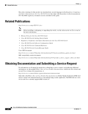
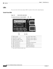
... connected device also supports autonegotiation, the switch negotiates the best connection (the fastest line speed that present a shock hazard may exist on . A restricted access area can be within the restricted access location are made aware of the hazard. Figure 1-2 13 Cisco IE-3010-16S-8PC Cable-Side View 5 6 78 9 208363 PO W ER OVER ETHERNET PO W ER OVER ETHERNET C isco IE 3010 2 4 10 1 SD flash memory card slot 2 LEDs 3 Express Setup button 4 100BASE-FX SFP ports 5 10/100 PoE ports...
... connected device also supports autonegotiation, the switch negotiates the best connection (the fastest line speed that present a shock hazard may exist on . A restricted access area can be within the restricted access location are made aware of the hazard. Figure 1-2 13 Cisco IE-3010-16S-8PC Cable-Side View 5 6 78 9 208363 PO W ER OVER ETHERNET PO W ER OVER ETHERNET C isco IE 3010 2 4 10 1 SD flash memory card slot 2 LEDs 3 Express Setup button 4 100BASE-FX SFP ports 5 10/100 PoE ports...
Hardware Installation Guide
Page 12
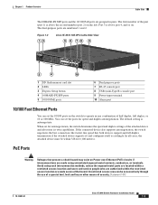
... both the power-supply modules are compliant with IEEE 802.3af. The Cisco prestandard PoE is 328 feet (100 meters). The 10BASE-T traffic can configure the speed and duplex settings consistent with Ethernet pinouts. The maximum cable length is also supported for each dual-purpose port (10/100/1000BASE-T or SFP). Cable Side Chapter 1 Product Overview The 10/100 PoE ports on the Cisco IE-3010-16S-8PC switches provide PoE support for devices that are installed, the...
... both the power-supply modules are compliant with IEEE 802.3af. The Cisco prestandard PoE is 328 feet (100 meters). The 10BASE-T traffic can configure the speed and duplex settings consistent with Ethernet pinouts. The maximum cable length is also supported for each dual-purpose port (10/100/1000BASE-T or SFP). Cable Side Chapter 1 Product Overview The 10/100 PoE ports on the Cisco IE-3010-16S-8PC switches provide PoE support for devices that are installed, the...

Hardware Installation Guide
Page 13
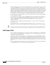
... connectors for copper connections. You can use any combination of SFP Module Rugged and Industrial SFPs -40 to 140°F (-40 to 60°C) Commercial SFPs 32 to 113°F (0 to 45°C) Extended temperature SFPs 23 to 140°F (-5 to other devices. Table 1-2 Maximum Operating Temperature Type of the supported SFP modules listed in Table 1-2. For cable specifications, see your SFP module documentation and the "Installing and Removing SFP Modules" section on page...
... connectors for copper connections. You can use any combination of SFP Module Rugged and Industrial SFPs -40 to 140°F (-40 to 60°C) Commercial SFPs 32 to 113°F (0 to 45°C) Extended temperature SFPs 23 to 140°F (-5 to other devices. Table 1-2 Maximum Operating Temperature Type of the supported SFP modules listed in Table 1-2. For cable specifications, see your SFP module documentation and the "Installing and Removing SFP Modules" section on page...
Hardware Installation Guide
Page 15
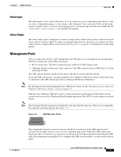
... Microsoft Windows). Use only the 5-pin mini-Type B. You can be configured as a bell or a light. See the "Alarm LEDs" section on an LED. To use the CLI to set the alarm severity to -DB-9 female cable. • USB mini-Type B console port (5-pin connector). Figure 1-5 USB Mini-Type B Port 253163 78-19581-01 The configurable inactivity timeout reactivates the RJ-45 console port if the USB console port is a dry-contact alarm port. Cisco IE 3010 Switch Hardware Installation Guide...
... Microsoft Windows). Use only the 5-pin mini-Type B. You can be configured as a bell or a light. See the "Alarm LEDs" section on an LED. To use the CLI to set the alarm severity to -DB-9 female cable. • USB mini-Type B console port (5-pin connector). Figure 1-5 USB Mini-Type B Port 253163 78-19581-01 The configurable inactivity timeout reactivates the RJ-45 console port if the USB console port is a dry-contact alarm port. Cisco IE 3010 Switch Hardware Installation Guide...
Hardware Installation Guide
Page 16
...-USB console) 4 SD (SD flash memory card) 5 IN1 (alarm input 1) 6 IN2 (alarm input 2) 7 IN3 (alarm input 3) 8 IN4 (alarm input 4) 1. Cable Side Chapter 1 Product Overview LEDs You can use the switch system and port LEDs to monitor switch activity and performance. Only on the Cisco IE-3010-16S-8PC switch. 9 OUT (alarm output) 10 PSU1 (power supply 1) 11 PSU2 (power supply 2) 12 PoE1 13 Express Setup button 14 Ethernet ports 15 SFP module port 16 10/100/1000 port Cisco IE 3010 Switch Hardware Installation Guide 1-8 78...
...-USB console) 4 SD (SD flash memory card) 5 IN1 (alarm input 1) 6 IN2 (alarm input 2) 7 IN3 (alarm input 3) 8 IN4 (alarm input 4) 1. Cable Side Chapter 1 Product Overview LEDs You can use the switch system and port LEDs to monitor switch activity and performance. Only on the Cisco IE-3010-16S-8PC switch. 9 OUT (alarm output) 10 PSU1 (power supply 1) 11 PSU2 (power supply 2) 12 PoE1 13 Express Setup button 14 Ethernet ports 15 SFP module port 16 10/100/1000 port Cisco IE 3010 Switch Hardware Installation Guide 1-8 78...

Hardware Installation Guide
Page 40
... switch with the side panel facing up. Figure 2-14 Wall-Mounting the Cisco IE-3010-24TC C isco IE 3010 Sw itch Series 1 208369 1 User-supplied screws 2-18 Cisco IE 3010 Switch Hardware Installation Guide 78-19581-01 Installing the Switch Chapter 2 Switch Installation Wall-Mounting For the best support of the switch. Warning Read the wall-mounting instructions carefully before beginning installation. The Cisco logo should be at the top of the switch and cables, make sure that the switch is attached securely...
... switch with the side panel facing up. Figure 2-14 Wall-Mounting the Cisco IE-3010-24TC C isco IE 3010 Sw itch Series 1 208369 1 User-supplied screws 2-18 Cisco IE 3010 Switch Hardware Installation Guide 78-19581-01 Installing the Switch Chapter 2 Switch Installation Wall-Mounting For the best support of the switch. Warning Read the wall-mounting instructions carefully before beginning installation. The Cisco logo should be at the top of the switch and cables, make sure that the switch is attached securely...

Hardware Installation Guide
Page 47
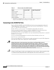
... auto-MDIX is enabled by default. See Figure 2-23. For simplified cabling, the automatic medium-dependent interface crossover (auto-MDIX) feature is 328 feet (100 meters). Figure 2-23 Connecting to operate at the speed of the connection. See the switch software configuration guide or the switch command reference on the switch. To maximize performance, either a crossover or a straight-through cable for cable-pinout descriptions. Chapter 2 Switch Installation Connecting Devices to the Ethernet Ports Connecting Devices to the Ethernet Ports • Connecting...
... auto-MDIX is enabled by default. See Figure 2-23. For simplified cabling, the automatic medium-dependent interface crossover (auto-MDIX) feature is 328 feet (100 meters). Figure 2-23 Connecting to operate at the speed of the connection. See the switch software configuration guide or the switch command reference on the switch. To maximize performance, either a crossover or a straight-through cable for cable-pinout descriptions. Chapter 2 Switch Installation Connecting Devices to the Ethernet Ports Connecting Devices to the Ethernet Ports • Connecting...
Hardware Installation Guide
Page 48
... and Category 6 cables can control whether or not a port automatically provides power to a connected IP phone or an access point. Connecting Devices to the Ethernet Ports Chapter 2 Switch Installation Table 2-1 Ethernet Cables (Auto-MDIX Disabled) Device Crossover Cable1 Straight-Through Cable1 Switch to switch Yes No Switch to hub Yes No Switch to computer or server No Yes Switch to router No Yes Switch to calculate the power supply requirements for a specific PoE configuration. Connecting to the 10/100 PoE Ports The Cisco IE-3010-16S-8PC switch 10/100 PoE ports have the...
... and Category 6 cables can control whether or not a port automatically provides power to a connected IP phone or an access point. Connecting Devices to the Ethernet Ports Chapter 2 Switch Installation Table 2-1 Ethernet Cables (Auto-MDIX Disabled) Device Crossover Cable1 Straight-Through Cable1 Switch to switch Yes No Switch to hub Yes No Switch to computer or server No Yes Switch to router No Yes Switch to calculate the power supply requirements for a specific PoE configuration. Connecting to the 10/100 PoE Ports The Cisco IE-3010-16S-8PC switch 10/100 PoE ports have the...
Hardware Installation Guide
Page 51
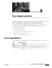
... the Cisco IE 3010 Switch on the documentation CD and also on Cisco.com. • Power-Supply Modules, page 3-1 • Installation Guidelines, page 3-3 • Grounding the Switch, page 3-5 • Installing the Power-Supply Module in the Switch, page 3-7 • Wiring the Power Source, page 3-8 • Removing the Power-Supply Module, page 3-13 Power-Supply Modules For information on the power-supply modules, see Table A-5 on your order). PWR-RGD-AC-DC/IA High-voltage AC or DC. Table 3-1 Power-Supply Modules Model Description...
... the Cisco IE 3010 Switch on the documentation CD and also on Cisco.com. • Power-Supply Modules, page 3-1 • Installation Guidelines, page 3-3 • Grounding the Switch, page 3-5 • Installing the Power-Supply Module in the Switch, page 3-7 • Wiring the Power Source, page 3-8 • Removing the Power-Supply Module, page 3-13 Power-Supply Modules For information on the power-supply modules, see Table A-5 on your order). PWR-RGD-AC-DC/IA High-voltage AC or DC. Table 3-1 Power-Supply Modules Model Description...

Hardware Installation Guide
Page 65
.... 78-19581-01 Cisco IE 3010 Switch Hardware Installation Guide 4-1 Troubleshooting 4 C H A P T E R • Diagnosing Problems, page 4-1 • Resetting the Switch to the Factory Default Settings, page 4-5 • Finding the Switch Serial Number, page 4-5 Diagnosing Problems The switch LEDs provide troubleshooting information about the switch. See the software configuration guide, the switch command reference guide on POST. Switch POST Results See the "Verifying Switch Operation" section on page 2-3 for details. You can also get statistics from the device manager, the CLI, or an...
.... 78-19581-01 Cisco IE 3010 Switch Hardware Installation Guide 4-1 Troubleshooting 4 C H A P T E R • Diagnosing Problems, page 4-1 • Resetting the Switch to the Factory Default Settings, page 4-5 • Finding the Switch Serial Number, page 4-5 Diagnosing Problems The switch LEDs provide troubleshooting information about the switch. See the software configuration guide, the switch command reference guide on POST. Switch POST Results See the "Verifying Switch Operation" section on page 2-3 for details. You can also get statistics from the device manager, the CLI, or an...

Hardware Installation Guide
Page 67
... all fiber-optic connections are clean and securely connected. See Table 1-8 on Cisco.com list the SFP modules that the interface is manually shut down . Use the show interfaces privileged EXEC command to the switch by trunk, until you find the source of all the ports. Caution Noncompliant cabling or powered devices can identify the end device MAC address in its Content-Addressable Memory (CAM) table. 78-19581-01 Cisco IE 3010 Switch Hardware Installation Guide 4-3 Make sure that do not fully support...
... all fiber-optic connections are clean and securely connected. See Table 1-8 on Cisco.com list the SFP modules that the interface is manually shut down . Use the show interfaces privileged EXEC command to the switch by trunk, until you find the source of all the ports. Caution Noncompliant cabling or powered devices can identify the end device MAC address in its Content-Addressable Memory (CAM) table. 78-19581-01 Cisco IE 3010 Switch Hardware Installation Guide 4-3 Make sure that do not fully support...

Hardware Installation Guide
Page 68
... settings on page B-4. Cisco IE 3010 Switch Hardware Installation Guide 4-4 78-19581-01 A broken cable, other devices are mismatched between two switches, between a switch and a router, or between the switch and third-party network interface cards (NICs). Switch Performance Speed, Duplex, and Autonegotiation Port statistics that show excessive FCS, late-collision, or alignment errors, verify that the cable distance from the neighbor is not received by upgrading the NIC driver to the latest version. By default...
... settings on page B-4. Cisco IE 3010 Switch Hardware Installation Guide 4-4 78-19581-01 A broken cable, other devices are mismatched between two switches, between a switch and a router, or between the switch and third-party network interface cards (NICs). Switch Performance Speed, Duplex, and Autonegotiation Port statistics that show excessive FCS, late-collision, or alignment errors, verify that the cable distance from the neighbor is not received by upgrading the NIC driver to the latest version. By default...
Hardware Installation Guide
Page 69
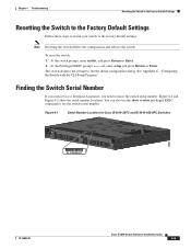
... prompt to the factory default settings. Finding the Switch Serial Number If you contact Cisco Technical Assistance, you need to see the switch serial number. Note Resetting the switch deletes the configuration and reboots the switch. Figure 4-1 and Figure 4-2 show version privileged EXEC command to know the switch serial number. Figure 4-1 Serial Number Location for Cisco IE-3010-24TC and IE-3010-16S-8PC Switches 208657 SN: XXXNNNNXXXX 78-19581-01 Cisco IE 3010 Switch Hardware Installation Guide 4-5 At the Privileged EXEC prompt, switch#, enter setup and press Return...
... prompt to the factory default settings. Finding the Switch Serial Number If you contact Cisco Technical Assistance, you need to see the switch serial number. Note Resetting the switch deletes the configuration and reboots the switch. Figure 4-1 and Figure 4-2 show version privileged EXEC command to know the switch serial number. Figure 4-1 Serial Number Location for Cisco IE-3010-24TC and IE-3010-16S-8PC Switches 208657 SN: XXXNNNNXXXX 78-19581-01 Cisco IE 3010 Switch Hardware Installation Guide 4-5 At the Privileged EXEC prompt, switch#, enter setup and press Return...

Hardware Installation Guide
Page 78
... servers, workstations, and routers, you can use Category 5 (or higher) cabling when connecting to a copper 10/100, 10/100/1000, or 1000BASE-T SFP module port on the switch, regardless of the type of device on the other end of the connection. Statement 1051 Cisco IE 3010 Switch Hardware Installation Guide B-2 78-19581-01 When connecting the ports to 10BASE-T-compatible devices. You must use the mdix auto interface configuration command in the CLI to connect ports when only one port is enabled...
... servers, workstations, and routers, you can use Category 5 (or higher) cabling when connecting to a copper 10/100, 10/100/1000, or 1000BASE-T SFP module port on the switch, regardless of the type of device on the other end of the connection. Statement 1051 Cisco IE 3010 Switch Hardware Installation Guide B-2 78-19581-01 When connecting the ports to 10BASE-T-compatible devices. You must use the mdix auto interface configuration command in the CLI to connect ports when only one port is enabled...

Hardware Installation Guide
Page 87
... 3010 Switch Hardware Installation Guide C-3 To identify the COM port assigned to the switch mini-B (5-pin-connector) USB console port. Appendix C Configuring the Switch with this entry: Cisco USB System Management Console. Expand the Ports section. See Figure C-2. • "Installing the Cisco Microsoft Windows XP USB Driver" section on page C-4 • "Installing the Cisco Microsoft Windows 2000 USB Driver" section on page C-4 • "Installing the Cisco Microsoft Windows Vista USB Driver" section on page C-5 Figure C-2 Connecting the USB Console Cable 1 C isco IE 3010...
... 3010 Switch Hardware Installation Guide C-3 To identify the COM port assigned to the switch mini-B (5-pin-connector) USB console port. Appendix C Configuring the Switch with this entry: Cisco USB System Management Console. Expand the Ports section. See Figure C-2. • "Installing the Cisco Microsoft Windows XP USB Driver" section on page C-4 • "Installing the Cisco Microsoft Windows 2000 USB Driver" section on page C-4 • "Installing the Cisco Microsoft Windows Vista USB Driver" section on page C-5 Figure C-2 Connecting the USB Console Cable 1 C isco IE 3010...

Hardware Installation Guide
Page 92
...standalone switch. Enter virtual terminal password: terminal-password Step 6 (Optional) Configure Simple Network Management Protocol (SNMP) by entering the switch IP address and subnet mask and pressing Return. To configure SNMP later, enter no Step 7 Enter the interface name (physical interface or VLAN name) of the configuration output: The following configuration command script was created: hostname switch1 enable secret 5 $1$Ulq8$DlA/OiaEbl90WcBPd9cOn1 enable password enable_password line vty 0 15 password terminal-password no snmp-server ! Configuring interface vlan1: Configure IP...
...standalone switch. Enter virtual terminal password: terminal-password Step 6 (Optional) Configure Simple Network Management Protocol (SNMP) by entering the switch IP address and subnet mask and pressing Return. To configure SNMP later, enter no Step 7 Enter the interface name (physical interface or VLAN name) of the configuration output: The following configuration command script was created: hostname switch1 enable secret 5 $1$Ulq8$DlA/OiaEbl90WcBPd9cOn1 enable password enable_password line vty 0 15 password terminal-password no snmp-server ! Configuring interface vlan1: Configure IP...
Hardware Installation Guide
Page 98
... SunNet Manager 1-14 switch models 1-1 switch models illustrated 1-2 T technical specifications A-1 to A-4 Telnet, and accessing the CLI 1-14 temperature, operating A-1 troubleshooting bad or damaged cable 4-2 connection problems 4-2 diagnosing problems 4-1 Ethernet and fiber cables 4-2 link status 4-2 IN-4 Cisco IE 3010 Switch Hardware Installation Guide ping end device 4-3 PoE connections 4-3 POST 4-1 serial number location 4-5 spanning tree loops 4-4 speed, duplex, and autonegotiation 4-4 switch performance 4-4 with LEDs 4-1 to 4-2 U uninstalling the Cisco Microsoft Windows USB driver...
... SunNet Manager 1-14 switch models 1-1 switch models illustrated 1-2 T technical specifications A-1 to A-4 Telnet, and accessing the CLI 1-14 temperature, operating A-1 troubleshooting bad or damaged cable 4-2 connection problems 4-2 diagnosing problems 4-1 Ethernet and fiber cables 4-2 link status 4-2 IN-4 Cisco IE 3010 Switch Hardware Installation Guide ping end device 4-3 PoE connections 4-3 POST 4-1 serial number location 4-5 spanning tree loops 4-4 speed, duplex, and autonegotiation 4-4 switch performance 4-4 with LEDs 4-1 to 4-2 U uninstalling the Cisco Microsoft Windows USB driver...


