Quick Start Guide
Page 10
... 12 • Setting the Chassis on a Desktop, page 13 • Setting the Cisco IAD2435 on page 18. Warning Ultimate disposal of this product should be installed and maintained by ...according to a general-purpose outlet could be disconnected 1) before unplugging the main power connector or 2) while the housing is open . Incorrectly connecting this product. Statement... only the mounting hardware supplied with telephone-network voltages. Statement 1074 7 Installing the Chassis This section provides the procedures for the Cisco IAD2430, Cisco IAD2431, and Cisco IAD2432 IADs. 10 See...
... 12 • Setting the Chassis on a Desktop, page 13 • Setting the Cisco IAD2435 on page 18. Warning Ultimate disposal of this product should be installed and maintained by ...according to a general-purpose outlet could be disconnected 1) before unplugging the main power connector or 2) while the housing is open . Incorrectly connecting this product. Statement... only the mounting hardware supplied with telephone-network voltages. Statement 1074 7 Installing the Chassis This section provides the procedures for the Cisco IAD2430, Cisco IAD2431, and Cisco IAD2432 IADs. 10 See...
Quick Start Guide
Page 16
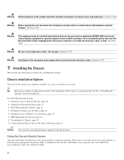
...a table. If the power supply is not supported, it could place strain on the power supply cable and cause it to reduce strain on the cable connections. • The power supply must rest on a horizontal surface such as shown in Figure 15. Figure 14 Mounting-Screw Slots for Wall-Mounting the Cisco IAD2435 IAD 1 1 2 ...panel must face upward and must be easily visible. • The back panel must face downward to disconnect from the wall. To wall-mount a Cisco IAD2435 IAD, follow these steps: Step 1 Step 2 Step 3 Secure two screws 7 inches (17.78 centimeters) apart into a wall and 5/32...
...a table. If the power supply is not supported, it could place strain on the power supply cable and cause it to reduce strain on the cable connections. • The power supply must rest on a horizontal surface such as shown in Figure 15. Figure 14 Mounting-Screw Slots for Wall-Mounting the Cisco IAD2435 IAD 1 1 2 ...panel must face upward and must be easily visible. • The back panel must face downward to disconnect from the wall. To wall-mount a Cisco IAD2435 IAD, follow these steps: Step 1 Step 2 Step 3 Secure two screws 7 inches (17.78 centimeters) apart into a wall and 5/32...

Quick Start Guide
Page 17
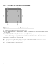
Figure 15 Mounting the Cisco IAD2435 IAD on a Wall 1 2 3 7 4 5 231985 6 Two number-six, 3/4-in . [0.40 cm]) 17 screws 1 Distance between the two screws 2 (7 in. [17.78 cm]) 3 Cisco IAD2435 router 4 Mounting-screw slots Maximum distance between the router Horizontal surface for supporting the 5 and the power supply (6 ft [1.8 m]) 6 power supply Distance between the screw and the 7 wall (5/32 in .
Figure 15 Mounting the Cisco IAD2435 IAD on a Wall 1 2 3 7 4 5 231985 6 Two number-six, 3/4-in . [0.40 cm]) 17 screws 1 Distance between the two screws 2 (7 in. [17.78 cm]) 3 Cisco IAD2435 router 4 Mounting-screw slots Maximum distance between the router Horizontal surface for supporting the 5 and the power supply (6 ft [1.8 m]) 6 power supply Distance between the screw and the 7 wall (5/32 in .

Quick Start Guide
Page 18
..., such as between the ground of a junction box (outlet) and the ground of a power tap, between the ground of a junction box and a metal water pipe, between the Cisco IAD chassis and the ground of a power tap, and between 0.0 and 0.5 ohm. Attach the ground lug (Figure 16 and Figure 17...a reliable earth ground; For the ground lug, use size AWG 18 (1 mm2) or larger wire and an appropriate user-supplied ring terminal. A good ground connection should read between the Cisco IAD chassis and the ground of a junction box. To connect the chassis to a reliable earth ground, follow these steps...
..., such as between the ground of a junction box (outlet) and the ground of a power tap, between the ground of a junction box and a metal water pipe, between the Cisco IAD chassis and the ground of a power tap, and between 0.0 and 0.5 ohm. Attach the ground lug (Figure 16 and Figure 17...a reliable earth ground; For the ground lug, use size AWG 18 (1 mm2) or larger wire and an appropriate user-supplied ring terminal. A good ground connection should read between the Cisco IAD chassis and the ground of a junction box. To connect the chassis to a reliable earth ground, follow these steps...
Quick Start Guide
Page 25
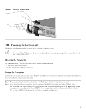
...data bits, 1 stop bit, and no parity. For the Cisco IAD2435 IAD, plug in the external power supply (see the power-on procedure in the Cisco IAD2430 Series Integrated Access Device Hardware Installation Guide. Caution Do not use AC and DC power at the same time. If you do, the unit stops .... Figure 26 Tightening the Velcro Strap FXS IAD2435-8FXS WAN FastEthernet T1/E1 0/1 0/0 281203 10 Powering On the Cisco IAD This section provides the procedure for powering on your terminal or PC, and configure it for Power-On You can power on the Cisco IAD2430 series IADs if it meets these steps...
...data bits, 1 stop bit, and no parity. For the Cisco IAD2435 IAD, plug in the external power supply (see the power-on procedure in the Cisco IAD2430 Series Integrated Access Device Hardware Installation Guide. Caution Do not use AC and DC power at the same time. If you do, the unit stops .... Figure 26 Tightening the Velcro Strap FXS IAD2435-8FXS WAN FastEthernet T1/E1 0/1 0/0 281203 10 Powering On the Cisco IAD This section provides the procedure for powering on your terminal or PC, and configure it for Power-On You can power on the Cisco IAD2430 series IADs if it meets these steps...
Quick Start Guide
Page 26
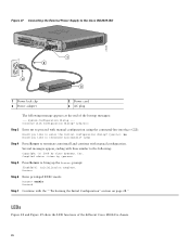
... the External Power Supply to the Cisco IAD2435 IAD 272268 FXS IAD2435-8FXS WAN/T1 CONSOLE 1 LAN 0 AUX 12V DC SA 1 2 4 3 1 Power lock clip 3 Power adapter 2 Power cord 4 AC plug The following : Copyright (c) 2008 by Step 5 Press Return to the following message appears at the end of the different Cisco IAD243x chassis... terminate autoinstall and continue with the ""Performing the Initial Configuration" section on page 28." Compiled by cisco Systems, Inc. Several messages appear, ending with lines similar to bring up the Router> prompt: flashfs[4]: Initialization complete.
... the External Power Supply to the Cisco IAD2435 IAD 272268 FXS IAD2435-8FXS WAN/T1 CONSOLE 1 LAN 0 AUX 12V DC SA 1 2 4 3 1 Power lock clip 3 Power adapter 2 Power cord 4 AC plug The following : Copyright (c) 2008 by Step 5 Press Return to the following message appears at the end of the different Cisco IAD243x chassis... terminate autoinstall and continue with the ""Performing the Initial Configuration" section on page 28." Compiled by cisco Systems, Inc. Several messages appear, ending with lines similar to bring up the Router> prompt: flashfs[4]: Initialization complete.

