
Installation Guide
Page 2
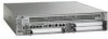
... field-replaceable units. but the shared port adapters in subslots 1-3 are field upgradable. The Cisco ASR 1002 Router supports upgradeable Cisco ASR1000-ESP5 or ASR1000-ESP10 assembly and the power supply modules as SPA bay 0. Figure 8-1 Cisco ASR 1002 Router-Front View 1 3 PWR ACTV STAT STBY ASR1000-ESP10 ASR 1002 STAT pwr min stat maj crit QE0 QE1 QE2 QE3 BOOT CARRIER C/A C/A A/L A/L 0 1 2 LINK...
... field-replaceable units. but the shared port adapters in subslots 1-3 are field upgradable. The Cisco ASR 1002 Router supports upgradeable Cisco ASR1000-ESP5 or ASR1000-ESP10 assembly and the power supply modules as SPA bay 0. Figure 8-1 Cisco ASR 1002 Router-Front View 1 3 PWR ACTV STAT STBY ASR1000-ESP10 ASR 1002 STAT pwr min stat maj crit QE0 QE1 QE2 QE3 BOOT CARRIER C/A C/A A/L A/L 0 1 2 LINK...
Installation Guide
Page 23
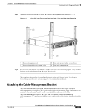
...-mount bracket on a Four-Post Rack-Front and Rear Rack-Mounting 1 STATUS A/L C/A STATUS 2 ASR 1002 stat min pwr maj crit SPA-4XOC3-POS 0 0 A/L C/A A/L C/A 1 1 A/L C/A 2 2 A/L C/A 3 3 A/L C/A SPA-4XOC3-POS SPA-4XOC3-POS A/L C/A A/L C/A 0 A/L C/A 1 A/L C/A 2 A/L C/A 3 A/L C/A...Cisco ASR 1000 Series Aggregation Services Routers Hardware Installation Guide 8-23 Figure 8-15 Cisco ASR 1002 Router on the chassis to provide cable-management to both brackets are level, or use a measuring tape to the "Attaching the Cable-Management Bracket" section on each card module...
...-mount bracket on a Four-Post Rack-Front and Rear Rack-Mounting 1 STATUS A/L C/A STATUS 2 ASR 1002 stat min pwr maj crit SPA-4XOC3-POS 0 0 A/L C/A A/L C/A 1 1 A/L C/A 2 2 A/L C/A 3 3 A/L C/A SPA-4XOC3-POS SPA-4XOC3-POS A/L C/A A/L C/A 0 A/L C/A 1 A/L C/A 2 A/L C/A 3 A/L C/A...Cisco ASR 1000 Series Aggregation Services Routers Hardware Installation Guide 8-23 Figure 8-15 Cisco ASR 1002 Router on the chassis to provide cable-management to both brackets are level, or use a measuring tape to the "Attaching the Cable-Management Bracket" section on each card module...
Quick Start Guide
Page 15
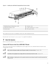
... Source cable 2 Management Ethernet cable 3 Console cable SPA-4XOC3-POS 4 Auxiliary cable 5 Cable-management "U" feature 6 Tie wrap for cables This completes the procedure for installing the AC power supply into the Cisco ASR 1002-F Router. Statement 1050 Warning Installation of the equipment must connect power to the Cisco ASR 1002-F Router This section provides instructions for installing the cables...
... Source cable 2 Management Ethernet cable 3 Console cable SPA-4XOC3-POS 4 Auxiliary cable 5 Cable-management "U" feature 6 Tie wrap for cables This completes the procedure for installing the AC power supply into the Cisco ASR 1002-F Router. Statement 1050 Warning Installation of the equipment must connect power to the Cisco ASR 1002-F Router This section provides instructions for installing the cables...
Quick Start Guide
Page 22
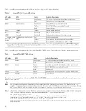
...Cisco ASR1002-ESP-F LEDs in the Cisco ASR 1000 Series Aggregation Services Routers SIP and SPA Hardware Installation Guide. Code has successfully downloaded and is a snapshot of messages that are compatible with Cisco ASR 1002 Built-in Gigabit Ethernet Ports (4x1GE), refer to the Modular Optics Compatibility section in the Cisco ASR 1002-F Router.... Table 3 provides information about the small form-factor pluggable (SFP) transceiver modules that are output on the console of the Cisco ASR 1002-F Router system after power-up **Built-in standby mode. The integrated services processor is...
...Cisco ASR1002-ESP-F LEDs in the Cisco ASR 1000 Series Aggregation Services Routers SIP and SPA Hardware Installation Guide. Code has successfully downloaded and is a snapshot of messages that are compatible with Cisco ASR 1002 Built-in Gigabit Ethernet Ports (4x1GE), refer to the Modular Optics Compatibility section in the Cisco ASR 1002-F Router.... Table 3 provides information about the small form-factor pluggable (SFP) transceiver modules that are output on the console of the Cisco ASR 1002-F Router system after power-up **Built-in standby mode. The integrated services processor is...

Quick Start Guide
Page 9
...bracket on the chassis to provide cable-management to both sides of the Cisco ASR 1002 Router in tandem with the SPA product feature cable-management device to allow easy installation and removal of the Cisco ASR 1002 Router. 9 Note Use the package of four screws that the cable-management ...cable-management brackets attached to each card module slot. Perform these brackets work in the rack: Step 1 Step 2 Align the cable-management bracket to the rack-mount bracket on one independent cable-management U type device with your Cisco ASR 1002 Router. Step 3 Using the bottom rack-mount...
...bracket on the chassis to provide cable-management to both sides of the Cisco ASR 1002 Router in tandem with the SPA product feature cable-management device to allow easy installation and removal of the Cisco ASR 1002 Router. 9 Note Use the package of four screws that the cable-management ...cable-management brackets attached to each card module slot. Perform these brackets work in the rack: Step 1 Step 2 Align the cable-management bracket to the rack-mount bracket on one independent cable-management U type device with your Cisco ASR 1002 Router. Step 3 Using the bottom rack-mount...

Quick Start Guide
Page 10
... (19.05 mm). 10 Note The Cisco ASR10002 Router does not support the Cisco ASR1000-ESP20 module. 2 R0 slot with embedded ASR1000-RP1 (Cisco ASR1000-RP2 is shipped with Telcordia grounding requirements is required for the Cisco ASR 1002 Router. Never defeat the ground conductor or operate... prevent a potential hazard in the absence of the Cisco ASR 1002 Router must be fully inserted and screwed in the accessory kit that is not supported by the Cisco ASR1002 Router) and embedded ASR1000-SIP10 4 Cisco ASR 1002 Router ground stud location Perform the following tools, equipment, ...
... (19.05 mm). 10 Note The Cisco ASR10002 Router does not support the Cisco ASR1000-ESP20 module. 2 R0 slot with embedded ASR1000-RP1 (Cisco ASR1000-RP2 is shipped with Telcordia grounding requirements is required for the Cisco ASR 1002 Router. Never defeat the ground conductor or operate... prevent a potential hazard in the absence of the Cisco ASR 1002 Router must be fully inserted and screwed in the accessory kit that is not supported by the Cisco ASR1002 Router) and embedded ASR1000-SIP10 4 Cisco ASR 1002 Router ground stud location Perform the following tools, equipment, ...
Quick Start Guide
Page 29
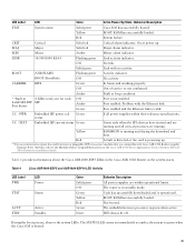
...in 4 LEDs total, one for each 4xGE SPA SFP SFP Port Status Off Amber Green Port is operational. CC - CC - Yellow ROMMON is valid. Table 4 provides information about the small form-factor pluggable (SFP) transceiver modules that are running. Code has successfully downloaded and...PWR Embedded SIP power rail status Green If all critical processes are compatible with Cisco ASR 1002 Built-in the Cisco ASR 1000 Series Aggregation Services Routers SIP and SPA Hardware Installation Guide. Table 4 Cisco ASR1000-ESP5 and ASR1000-ESP10 LED Activity LED Label PWR STAT LED Power Status...
...in 4 LEDs total, one for each 4xGE SPA SFP SFP Port Status Off Amber Green Port is operational. CC - CC - Yellow ROMMON is valid. Table 4 provides information about the small form-factor pluggable (SFP) transceiver modules that are running. Code has successfully downloaded and...PWR Embedded SIP power rail status Green If all critical processes are compatible with Cisco ASR 1002 Built-in the Cisco ASR 1000 Series Aggregation Services Routers SIP and SPA Hardware Installation Guide. Table 4 Cisco ASR1000-ESP5 and ASR1000-ESP10 LED Activity LED Label PWR STAT LED Power Status...

Configuration Guide
Page 305
... : command output MIME Type : text/plain Command Output Text : NAME: "Chassis", DESCR: "Cisco ASR1006 Chassis" PID: ASR1006 , VID: V00, SN: FOX105101DH NAME: "module 0", DESCR: "Cisco ASR1000 SPA Interface Processor 10" PID: MCP-CC , VID: V00, SN: JAB1104064W Cisco ASR 1000 Series Aggregation Services Routers Software Configuration Guide 49 Error code = 0x1 (DIAG_FAILURE) *Dec 3 12:25:54.405...
... : command output MIME Type : text/plain Command Output Text : NAME: "Chassis", DESCR: "Cisco ASR1006 Chassis" PID: ASR1006 , VID: V00, SN: FOX105101DH NAME: "module 0", DESCR: "Cisco ASR1000 SPA Interface Processor 10" PID: MCP-CC , VID: V00, SN: JAB1104064W Cisco ASR 1000 Series Aggregation Services Routers Software Configuration Guide 49 Error code = 0x1 (DIAG_FAILURE) *Dec 3 12:25:54.405...
Configuration Guide
Page 306
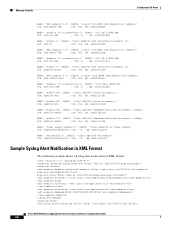
...: "Fan Module 1", DESCR: "Cisco ASR1006 Fan Module" PID: TBD000000000000000, VID: +^A , SN: ART1115P00D Sample Syslog Alert Notification in XML Format The following example shows a Syslog alert notification in XML format: http://tools.cisco.com/neddce/services/DDCEService http://www.cisco.com/appliance/uri http://www.cisco.com/appliance/uri M0:FOX105101DH:CEC1E73E Cisco ASR 1000 Series Aggregation Services Routers Software...
...: "Fan Module 1", DESCR: "Cisco ASR1006 Fan Module" PID: TBD000000000000000, VID: +^A , SN: ART1115P00D Sample Syslog Alert Notification in XML Format The following example shows a Syslog alert notification in XML format: http://tools.cisco.com/neddce/services/DDCEService http://www.cisco.com/appliance/uri http://www.cisco.com/appliance/uri M0:FOX105101DH:CEC1E73E Cisco ASR 1000 Series Aggregation Services Routers Software...
Configuration Guide
Page 311
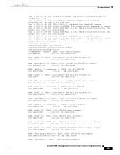
Error code = 0x1 (DIAG_FAILURE) *Dec 3 12:25:54.405 IST: %SYS-5-CONFIG_I: Configured from console by console *Dec 3 12:25:34.356 IST: %DIAG-3-TEST_FAIL: slot R0: TestErrorCounterMonitor{ID=1} has failed. Configuring Call Home Message Contents *Dec 3 12:17:17.905 IST: %LINEPROTO-5-UPDOWN: Line protocol on Interface POS2/3/0, changed state to up *Dec 3 12:22:01.574 IST: %IP-4-DUPADDR: Duplicate address 172.27.55.233 on GigabitEthernet0, sourced by 001a.3044.1ec0 *Dec 3 12:23:47.613 IST: %SYS-5-CONFIG_I: Configured from console by console *Dec 3 12:24:37.134 IST: %CLEAR-5-COUNTERS...
Error code = 0x1 (DIAG_FAILURE) *Dec 3 12:25:54.405 IST: %SYS-5-CONFIG_I: Configured from console by console *Dec 3 12:25:34.356 IST: %DIAG-3-TEST_FAIL: slot R0: TestErrorCounterMonitor{ID=1} has failed. Configuring Call Home Message Contents *Dec 3 12:17:17.905 IST: %LINEPROTO-5-UPDOWN: Line protocol on Interface POS2/3/0, changed state to up *Dec 3 12:22:01.574 IST: %IP-4-DUPADDR: Duplicate address 172.27.55.233 on GigabitEthernet0, sourced by 001a.3044.1ec0 *Dec 3 12:23:47.613 IST: %SYS-5-CONFIG_I: Configured from console by console *Dec 3 12:24:37.134 IST: %CLEAR-5-COUNTERS...

Configuration Guide
Page 462
...43 server IDs description 44 shell manager process, overview 7 show history command 5 SIPBase, Overview 3 SIPSPA, Overview 3 Software Modules, Overview 3 Software Packaging, Overview 1 source IDs call home event format 43 SPA driver process, overview 7 SSO, using SSO to enable second IOS Process on single RP example 15 Stateful Switchover (SSO), ...web user interface, overview 1 web user interface, tricks and tips 10 web user interface, using auto-refresh 9 web user interface access, configuring 5 IN-IV Cisco ASR 1000 Series Aggregation Services Routers Software Configuration Guide OL-16506-11
...43 server IDs description 44 shell manager process, overview 7 show history command 5 SIPBase, Overview 3 SIPSPA, Overview 3 Software Modules, Overview 3 Software Packaging, Overview 1 source IDs call home event format 43 SPA driver process, overview 7 SSO, using SSO to enable second IOS Process on single RP example 15 Stateful Switchover (SSO), ...web user interface, overview 1 web user interface, tricks and tips 10 web user interface, using auto-refresh 9 web user interface access, configuring 5 IN-IV Cisco ASR 1000 Series Aggregation Services Routers Software Configuration Guide OL-16506-11


