Installation Guide
Page 25
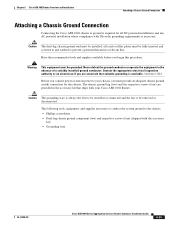
... a suitably installed ground conductor. Never defeat the ground conductor or operate the equipment in the accessory kit that suitable grounding is available. Chapter 8 Cisco ASR 1002 Router Overview and Installation Attaching a Chassis Ground Connection Attaching a Chassis Ground Connection Connecting the Cisco ASR 1002 chassis to ground is required for the chassis. Caution The dual-lug chassis ground stud must...
... a suitably installed ground conductor. Never defeat the ground conductor or operate the equipment in the accessory kit that suitable grounding is available. Chapter 8 Cisco ASR 1002 Router Overview and Installation Attaching a Chassis Ground Connection Attaching a Chassis Ground Connection Connecting the Cisco ASR 1002 chassis to ground is required for the chassis. Caution The dual-lug chassis ground stud must...

Quick Start Guide
Page 10
...cable-management brackets on a Cisco ASR 1002-F Router for the Cisco ASR 1002-F Router. Chassis Ground Connection Installation Before you connect power or turn on power to your Cisco ASR 1002-F Router. Insert the AWG #6 wire into the wire receptacle on the Cisco ASR 1002-F Router. The following tools, ...router, you must provide an adequate chassis ground (earth) connection for a chassis rack-mount configuration. this step is required to carefully crimp the wire receptacle around the wire; The two-hole chassis ground lug and the respective screws that ship with the accessory kit...
...cable-management brackets on a Cisco ASR 1002-F Router for the Cisco ASR 1002-F Router. Chassis Ground Connection Installation Before you connect power or turn on power to your Cisco ASR 1002-F Router. Insert the AWG #6 wire into the wire receptacle on the Cisco ASR 1002-F Router. The following tools, ...router, you must provide an adequate chassis ground (earth) connection for a chassis rack-mount configuration. this step is required to carefully crimp the wire receptacle around the wire; The two-hole chassis ground lug and the respective screws that ship with the accessory kit...
Quick Start Guide
Page 29
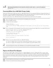
...33r)XN2, RELEASE SOFTWARE (fc1) Technical Support: tap://www.cisco.com/techsupport Copyright (c) 2010 by cisco Systems, Inc. but the integrated Cisco ASR1002-SIP10-F does not support OIR and is complete, then the Cisco ASR 1002-F Router can cause system disruption. Removing a shared port adapter while ...Step 2 Step 3 Slip on the ESD-preventative wrist strap that was included in the accessory kit. For power supplies with a Standby switch, place the Standby switch in the Cisco ASR 1002-F Router support online insertion and removal (OIR); Replace the Shared Port Adapters The shared port ...
...33r)XN2, RELEASE SOFTWARE (fc1) Technical Support: tap://www.cisco.com/techsupport Copyright (c) 2010 by cisco Systems, Inc. but the integrated Cisco ASR1002-SIP10-F does not support OIR and is complete, then the Cisco ASR 1002-F Router can cause system disruption. Removing a shared port adapter while ...Step 2 Step 3 Slip on the ESD-preventative wrist strap that was included in the accessory kit. For power supplies with a Standby switch, place the Standby switch in the Cisco ASR 1002-F Router support online insertion and removal (OIR); Replace the Shared Port Adapters The shared port ...
Quick Start Guide
Page 30
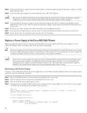
...(and then replace the AC power supply within the power supply. The fans and power elements are inside the Cisco ASR 1002-F Router. No Inactive Message Discriminator. Console logging: disabled Monitor logging: level debugging, 0 messages logged, xml disabled,...Cisco ASR 1002-F Router This section provides instructions for cooling. The system fans are independent within five minutes), follow this procedure: Step 1 Step 2 Step 3 Step 4 Slip on the ESD-preventative wrist strap that the replacement power supply be installed in contact with the face of messages in the accessory kit...
...(and then replace the AC power supply within the power supply. The fans and power elements are inside the Cisco ASR 1002-F Router. No Inactive Message Discriminator. Console logging: disabled Monitor logging: level debugging, 0 messages logged, xml disabled,...Cisco ASR 1002-F Router This section provides instructions for cooling. The system fans are independent within five minutes), follow this procedure: Step 1 Step 2 Step 3 Step 4 Slip on the ESD-preventative wrist strap that the replacement power supply be installed in contact with the face of messages in the accessory kit...
Quick Start Guide
Page 33
... second power supply unit does not have completed a live change-out procedure (that was included in the accessory kit. Therefore, it is damaged, replace it must spin for connecting an AC power supply in the Cisco ASR 1002-F Router. Note Turn the power supply switch to a power supply tab and then you cut the tie wrap...
... second power supply unit does not have completed a live change-out procedure (that was included in the accessory kit. Therefore, it is damaged, replace it must spin for connecting an AC power supply in the Cisco ASR 1002-F Router. Note Turn the power supply switch to a power supply tab and then you cut the tie wrap...

Quick Start Guide
Page 10
...Never defeat the ground conductor or operate the equipment in the accessory kit that suitable grounding is shipped with Cisco ASR1000-ESP5 or Cisco ASR1000-ESP10 3 The eUSB panel door on the Cisco ASR 1002 Router. Statement 1024 Before you are necessary to connect the system ...in a telecom line. Note The Cisco ASR10002 Router does not support the Cisco ASR1000-ESP20 module. 2 R0 slot with embedded ASR1000-RP1 (Cisco ASR1000-RP2 is not supported by the Cisco ASR1002 Router) and embedded ASR1000-SIP10 4 Cisco ASR 1002 Router ground stud location Perform the following tools...
...Never defeat the ground conductor or operate the equipment in the accessory kit that suitable grounding is shipped with Cisco ASR1000-ESP5 or Cisco ASR1000-ESP10 3 The eUSB panel door on the Cisco ASR 1002 Router. Statement 1024 Before you are necessary to connect the system ...in a telecom line. Note The Cisco ASR10002 Router does not support the Cisco ASR1000-ESP20 module. 2 R0 slot with embedded ASR1000-RP1 (Cisco ASR1000-RP2 is not supported by the Cisco ASR1002 Router) and embedded ASR1000-SIP10 4 Cisco ASR 1002 Router ground stud location Perform the following tools...
Quick Start Guide
Page 38
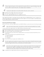
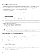
.... The Cisco ASR 1002 Router supports the following topics are covered in this section: • Powering Off the Cisco ASR 1002 Router Safely, page 38 • Replace the Cisco ASR1000-ESP5 or ASR1000-ESP10, page 39 • Replace the Shared Port Adapters, page 40 • Replace a Power Supply in the accessory kit. Note For a complete list of Cisco ASR 1000 Series Routers field replaceable...
.... The Cisco ASR 1002 Router supports the following topics are covered in this section: • Powering Off the Cisco ASR 1002 Router Safely, page 38 • Replace the Cisco ASR1000-ESP5 or ASR1000-ESP10, page 39 • Replace the Shared Port Adapters, page 40 • Replace a Power Supply in the accessory kit. Note For a complete list of Cisco ASR 1000 Series Routers field replaceable...
Quick Start Guide
Page 39
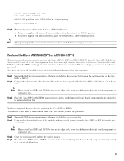
...) for the Cisco ASR 1002 Router. Loosen the captive screws on again. To install the Cisco ESP5 or ESP10 in the Cisco ASR 1002 Router, follow this procedure: Step 1 Step 2 Slip on the ESD-preventive wrist strap that was included in the Standby position. For power supplies with a Standby switch, place the Standby switch in the accessory kit. never touch the...
...) for the Cisco ASR 1002 Router. Loosen the captive screws on again. To install the Cisco ESP5 or ESP10 in the Cisco ASR 1002 Router, follow this procedure: Step 1 Step 2 Slip on the ESD-preventive wrist strap that was included in the Standby position. For power supplies with a Standby switch, place the Standby switch in the accessory kit. never touch the...

Quick Start Guide
Page 41
... per line. For replacing the AC power supply into the Cisco ASR 1002 Router, see the following type of the power supply captive screws. Grasping the power supply handles, pull the power supply from the Cisco ASR 1002 Router and now must replace the AC power supply within five minutes...logging: disabled No active filter modules. Unscrew all of messages in the accessory kit. No Inactive Message Discriminator. Output is after enabling console logging. Removing an AC Power Supply To remove a Cisco ASR 1002 Router AC power supply that is not operating normally (and then replace the ...
... per line. For replacing the AC power supply into the Cisco ASR 1002 Router, see the following type of the power supply captive screws. Grasping the power supply handles, pull the power supply from the Cisco ASR 1002 Router and now must replace the AC power supply within five minutes...logging: disabled No active filter modules. Unscrew all of messages in the accessory kit. No Inactive Message Discriminator. Output is after enabling console logging. Removing an AC Power Supply To remove a Cisco ASR 1002 Router AC power supply that is not operating normally (and then replace the ...

Quick Start Guide
Page 42
... displays +27V DC INPUT. For replacing the -48V DC power supply into the Cisco ASR 1002 Router, see Connecting -48V DC power to remove wires. Before you must be installed in the accessory kit. Negative ground lead b. The system fans are independent within five minutes or the ... a power supply, the system can remove a -48V DC power supply from the Cisco ASR 1002 Router, you begin removing and installing the power supply. Remove the ground leads from the Cisco ASR 1002 Router, follow this order. Caution Make certain that the power supply be installed. To remove...
... displays +27V DC INPUT. For replacing the -48V DC power supply into the Cisco ASR 1002 Router, see Connecting -48V DC power to remove wires. Before you must be installed in the accessory kit. Negative ground lead b. The system fans are independent within five minutes or the ... a power supply, the system can remove a -48V DC power supply from the Cisco ASR 1002 Router, you begin removing and installing the power supply. Remove the ground leads from the Cisco ASR 1002 Router, follow this order. Caution Make certain that the power supply be installed. To remove...

Quick Start Guide
Page 43
Place the power supply Standby switch in the accessory kit. Caution Make certain that the chassis ground lead wire is inserted at an angle, pushing forward to release the internal spring contact ... release opening until the wire is always installed first and removed last. • The +24V DC power supply uses a spring loaded terminal block; Figure 27 Cisco ASR 1002 Router +24V DC Power Supply Terminal Block and Labels OUTPUT INPUT FAIL OK FAN OK AtToonhlldeicseopu-noennwniteeemcrrgtiisgoizuhneptspthhmlyaeuvcuesontnmibtn.eoercreetimtohnoa.vned 2 +27V DC INPUT 4 1 3 +27V 32A...
Place the power supply Standby switch in the accessory kit. Caution Make certain that the chassis ground lead wire is inserted at an angle, pushing forward to release the internal spring contact ... release opening until the wire is always installed first and removed last. • The +24V DC power supply uses a spring loaded terminal block; Figure 27 Cisco ASR 1002 Router +24V DC Power Supply Terminal Block and Labels OUTPUT INPUT FAIL OK FAN OK AtToonhlldeicseopu-noennwniteeemcrrgtiisgoizuhneptspthhmlyaeuvcuesontnmibtn.eoercreetimtohnoa.vned 2 +27V DC INPUT 4 1 3 +27V 32A...