
Installation Guide
Page 2
...; Cisco ASR 1002 Router Slot Numbering, page 8-4 Front View Figure 8-1 shows the Cisco ASR 1002 Router with T1/E1 BITS interface or SPAs as field-replaceable units. The Cisco ASR 1002 Router supports upgradeable Cisco ASR1000-ESP5 or ASR1000-ESP10 assembly and the power supply modules as timing sources. • A built- The Cisco embedded ASR1000-SIP10 and Cisco built-in subslots 1-3 are not upgradeable; Figure 8-1 Cisco ASR 1002 Router-Front...
...; Cisco ASR 1002 Router Slot Numbering, page 8-4 Front View Figure 8-1 shows the Cisco ASR 1002 Router with T1/E1 BITS interface or SPAs as field-replaceable units. The Cisco ASR 1002 Router supports upgradeable Cisco ASR1000-ESP5 or ASR1000-ESP10 assembly and the power supply modules as timing sources. • A built- The Cisco embedded ASR1000-SIP10 and Cisco built-in subslots 1-3 are not upgradeable; Figure 8-1 Cisco ASR 1002 Router-Front...
Installation Guide
Page 6
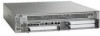
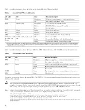
LED Label LED 1 PWR Power 2 ACTV 3 STAT Active STATUS 4 STBY Standby Color Solid green Off Green Green Yellow Red None Behavior in the Cisco ASR 1002 Router The Cisco ASR 1002 Router power supply module supports the following Cisco power supplies: • AC power supply operates between 85VAC to 264VAC and DC operates between -40.5 to -72VDC • -48 VDC power...
LED Label LED 1 PWR Power 2 ACTV 3 STAT Active STATUS 4 STBY Standby Color Solid green Off Green Green Yellow Red None Behavior in the Cisco ASR 1002 Router The Cisco ASR 1002 Router power supply module supports the following Cisco power supplies: • AC power supply operates between 85VAC to 264VAC and DC operates between -40.5 to -72VDC • -48 VDC power...
Installation Guide
Page 23
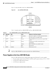
...each rack-mount bracket on the chassis to provide cable-management to the equipment rack (see Figure 8-15). Chapter 8 Cisco ASR 1002 Router Overview and Installation Attaching the Cable-Management Bracket Step 5 Tighten all screws on each side to secure the chassis to...with four screws and provides cable dressing of cables. This completes the procedure for the Cisco ASR 1002 Router contain one independent cable-management "U" type features with card orientation). Figure 8-15 Cisco ASR 1002 Router on page 8-23 to allow easy installation and removal of each card module slot.
...each rack-mount bracket on the chassis to provide cable-management to the equipment rack (see Figure 8-15). Chapter 8 Cisco ASR 1002 Router Overview and Installation Attaching the Cable-Management Bracket Step 5 Tighten all screws on each side to secure the chassis to...with four screws and provides cable dressing of cables. This completes the procedure for the Cisco ASR 1002 Router contain one independent cable-management "U" type features with card orientation). Figure 8-15 Cisco ASR 1002 Router on page 8-23 to allow easy installation and removal of each card module slot.

Installation Guide
Page 31
...grounding is available. Connecting AC Input Power to Cisco ASR 1002 Router To connect AC power to install, replace, or service this equipment. Statement 1030 Warning Never install an AC power module and a DC power module in the absence of a suitably installed ground ...equipment must comply with local and national electrical codes. Note Turn the power switch to your Cisco ASR 1002 Router. Chapter 8 Cisco ASR 1002 Router Overview and Installation Cisco ASR 1002 Router Power Supplies Warning Before performing any of the following procedures, ensure that the power switch is in ...
...grounding is available. Connecting AC Input Power to Cisco ASR 1002 Router To connect AC power to install, replace, or service this equipment. Statement 1030 Warning Never install an AC power module and a DC power module in the absence of a suitably installed ground ...equipment must comply with local and national electrical codes. Note Turn the power switch to your Cisco ASR 1002 Router. Chapter 8 Cisco ASR 1002 Router Overview and Installation Cisco ASR 1002 Router Power Supplies Warning Before performing any of the following procedures, ensure that the power switch is in ...
Quick Start Guide
Page 15
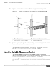
Warning Never install an AC power module and a DC power module in the cable-management bracket. Connect AC Power to complete the installation. 7 Start the System Before you start the system, you begin. Statement 1046 15 Figure 12 Bundling Cisco ASR 1002-F Integrated Route Processor Cables 123 4 5 0 A/L C/A 1 A/L C/A 2 A/L ... "U" feature 6 Tie wrap for cables This completes the procedure for installing the AC power supply into the Cisco ASR 1002-F Router. Statement 1050 Warning Installation of the equipment must always be made first and disconnected last. Read the safety...
Warning Never install an AC power module and a DC power module in the cable-management bracket. Connect AC Power to complete the installation. 7 Start the System Before you start the system, you begin. Statement 1046 15 Figure 12 Bundling Cisco ASR 1002-F Integrated Route Processor Cables 123 4 5 0 A/L C/A 1 A/L C/A 2 A/L ... "U" feature 6 Tie wrap for cables This completes the procedure for installing the AC power supply into the Cisco ASR 1002-F Router. Statement 1050 Warning Installation of the equipment must always be made first and disconnected last. Read the safety...
Quick Start Guide
Page 22
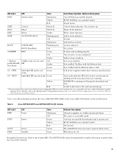
... is valid. **For more information about the Cisco ASR1002-ESP-F LEDs in the Cisco ASR 1002-F Router as amber, then turns to initialize. Note The system boots differently depending on the Cisco ASR 1002-F Router faceplate. Table 4 provides information about the small form-factor pluggable (SFP) transceiver modules that are within operational limits. Table 3 Cisco ASR 1002-F Router LED Activity LED Label LED Color Behavior...
... is valid. **For more information about the Cisco ASR1002-ESP-F LEDs in the Cisco ASR 1002-F Router as amber, then turns to initialize. Note The system boots differently depending on the Cisco ASR 1002-F Router faceplate. Table 4 provides information about the small form-factor pluggable (SFP) transceiver modules that are within operational limits. Table 3 Cisco ASR 1002-F Router LED Activity LED Label LED Color Behavior...
Quick Start Guide
Page 31
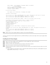
... logged, xml disabled, filtering disabled Exception Logging: size (4096 bytes) Count and timestamp logging messages: disabled Persistent logging: disabled No active filter modules. Installing the AC Power Supply Step 1 Step 2 Step 3 Step 4 Step 5 Insert an AC power supply in power supply Slot 0 or... Off (O) position. End with other cables or wires, dress the AC power cable in the log). 2ru_perf2#conf Configuring from the Cisco ASR 1002-F Router and now must replace the AC power supply within five minutes. a. Trap logging: level informational, 78 message lines logged Log Buffer ...
... logged, xml disabled, filtering disabled Exception Logging: size (4096 bytes) Count and timestamp logging messages: disabled Persistent logging: disabled No active filter modules. Installing the AC Power Supply Step 1 Step 2 Step 3 Step 4 Step 5 Insert an AC power supply in power supply Slot 0 or... Off (O) position. End with other cables or wires, dress the AC power cable in the log). 2ru_perf2#conf Configuring from the Cisco ASR 1002-F Router and now must replace the AC power supply within five minutes. a. Trap logging: level informational, 78 message lines logged Log Buffer ...

Quick Start Guide
Page 34
.... Statement 1074 Step 1 Step 2 Step 3 Step 4 At the rear of the router, check that the negative and positive leads are disconnected from the Cisco ASR 1002-F Router. Statement 1050 Warning Installation of the DC power source at the DC power source. Note...DC power supply in the Standby position. Figure 20 Cisco ASR 1002-F Router Terminal Block -48V/-60V 16A 280291 1 Negative lead 2 Positive lead 3 Earth ground symbol Warning Never install an AC power module and a DC power module in the Cisco ASR 1002-F Router. You have completed the procedure for ground. Using ...
.... Statement 1074 Step 1 Step 2 Step 3 Step 4 At the rear of the router, check that the negative and positive leads are disconnected from the Cisco ASR 1002-F Router. Statement 1050 Warning Installation of the DC power source at the DC power source. Note...DC power supply in the Standby position. Figure 20 Cisco ASR 1002-F Router Terminal Block -48V/-60V 16A 280291 1 Negative lead 2 Positive lead 3 Earth ground symbol Warning Never install an AC power module and a DC power module in the Cisco ASR 1002-F Router. You have completed the procedure for ground. Using ...

Quick Start Guide
Page 9
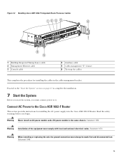
.... These brackets are mounted to the rack-mount brackets using screws to the cable-management bracket. Figure 5 Attaching the Cable-Management Brackets to the Cisco ASR 1002 Router 1 STATUS A/L C/A A/L C/A A/L C/A STATUS 3 2 ASR 1002 stat min pwr maj crit STAT QE0 QE1 QE2 QE3 BOOT CARRIER MTS LINK MGMT AUX CON PWR STAT SPA-4XOC3-POS 0 0 A/L C/A A/L C/A 1 1 A/L C/A 2 2 A/L C/A 3 3 A/L C/A...-management bracket should be mounted to each rack-mount bracket on one independent cable-management U type device with two screws for each card module slot.
.... These brackets are mounted to the rack-mount brackets using screws to the cable-management bracket. Figure 5 Attaching the Cable-Management Brackets to the Cisco ASR 1002 Router 1 STATUS A/L C/A A/L C/A A/L C/A STATUS 3 2 ASR 1002 stat min pwr maj crit STAT QE0 QE1 QE2 QE3 BOOT CARRIER MTS LINK MGMT AUX CON PWR STAT SPA-4XOC3-POS 0 0 A/L C/A A/L C/A 1 1 A/L C/A 2 2 A/L C/A 3 3 A/L C/A...-management bracket should be mounted to each rack-mount bracket on one independent cable-management U type device with two screws for each card module slot.

Quick Start Guide
Page 10
...Cisco ASR10002 Router does not support the Cisco ASR1000-ESP20 module. 2 R0 slot with the eUSB flash card, the chassis should be returned. This completes the procedure for installing the cable-management brackets on a Cisco ASR 1002 Router for the location of the chassis ground connector on the Cisco ASR 1002 Router... STATUS 1 2 280283 1 F0 with Cisco ASR1000-ESP5 or Cisco ASR1000-ESP10 3 The eUSB panel door on the power to earth ground is not supported by the Cisco ASR1002 Router) and embedded ASR1000-SIP10 4 Cisco ASR 1002 Router ground stud location Perform the following tools,...
...Cisco ASR10002 Router does not support the Cisco ASR1000-ESP20 module. 2 R0 slot with the eUSB flash card, the chassis should be returned. This completes the procedure for installing the cable-management brackets on a Cisco ASR 1002 Router for the location of the chassis ground connector on the Cisco ASR 1002 Router... STATUS 1 2 280283 1 F0 with Cisco ASR1000-ESP5 or Cisco ASR1000-ESP10 3 The eUSB panel door on the power to earth ground is not supported by the Cisco ASR1002 Router) and embedded ASR1000-SIP10 4 Cisco ASR 1002 Router ground stud location Perform the following tools,...

Quick Start Guide
Page 15
...This unit might have more than one power supply connection. Figure 12 AC Power Supply for the Cisco ASR 1006 Router: 50A U.S. maximum: Cisco ASR 1002 Router: 30A (-48V) U.S. Table 1 Cisco ASR 1002 Router AC Power Supply LEDs 15 Statement 1074 Warning When installing or replacing the unit, the ground ...Figure 12 shows the AC power supply for the Cisco ASR 1002 Router. Statement 1046 Warning This equipment must be removed to de-energize the unit. Warning Never install an AC power module and a DC power module in the absence of the equipment must be removed ...
...This unit might have more than one power supply connection. Figure 12 AC Power Supply for the Cisco ASR 1006 Router: 50A U.S. maximum: Cisco ASR 1002 Router: 30A (-48V) U.S. Table 1 Cisco ASR 1002 Router AC Power Supply LEDs 15 Statement 1074 Warning When installing or replacing the unit, the ground ...Figure 12 shows the AC power supply for the Cisco ASR 1002 Router. Statement 1046 Warning This equipment must be removed to de-energize the unit. Warning Never install an AC power module and a DC power module in the absence of the equipment must be removed ...

Quick Start Guide
Page 20
... the site power source and the circuit breaker is turned off. Figure 17 Cisco ASR 1002 Router -48V DC Terminal Block -48V/-60V 16A 280291 1 Negative lead 2 Positive lead 3 Earth ground symbol Warning Never install an AC power module and a DC power module in the Standby position. Insert a -48V DC power supply in power supply slot...
... the site power source and the circuit breaker is turned off. Figure 17 Cisco ASR 1002 Router -48V DC Terminal Block -48V/-60V 16A 280291 1 Negative lead 2 Positive lead 3 Earth ground symbol Warning Never install an AC power module and a DC power module in the Standby position. Insert a -48V DC power supply in power supply slot...
Quick Start Guide
Page 29
... each 4xGE SPA SFP SFP Port Status Off Amber Green Port is in the Cisco ASR 1002 Router as amber, then turns to the Modular Optics Compatibility section in the Cisco ASR 1000 Series Aggregation Services Routers SIP and SPA Hardware Installation Guide. Will always be off. BOOT ROM has ... RJ-45 Flashing green Link activity indicator. Table 4 provides information about the small form-factor pluggable (SFP) transceiver modules that are compatible with Cisco ASR 1002 Built-in Gigabit Ethernet Ports (4x1GE), refer to green when the Cisco IOS is valid. The router is not enabled.
... each 4xGE SPA SFP SFP Port Status Off Amber Green Port is in the Cisco ASR 1002 Router as amber, then turns to the Modular Optics Compatibility section in the Cisco ASR 1000 Series Aggregation Services Routers SIP and SPA Hardware Installation Guide. Will always be off. BOOT ROM has ... RJ-45 Flashing green Link activity indicator. Table 4 provides information about the small form-factor pluggable (SFP) transceiver modules that are compatible with Cisco ASR 1002 Built-in Gigabit Ethernet Ports (4x1GE), refer to green when the Cisco IOS is valid. The router is not enabled.
Quick Start Guide
Page 39
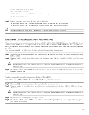
... ASR1000-ESP10 This section provides instructions for the Cisco ASR 1002 Router. To remove the Cisco ESP5 or ESP10 from the Cisco ASR 1002 Router. You have completed the procedure for removing the Cisco ESP5 or ESP10. Loosen the captive screws on both sides of the module, with two hands, gently slide the Cisco ESP5 or ESP10 out of the chassis slot...
... ASR1000-ESP10 This section provides instructions for the Cisco ASR 1002 Router. To remove the Cisco ESP5 or ESP10 from the Cisco ASR 1002 Router. You have completed the procedure for removing the Cisco ESP5 or ESP10. Loosen the captive screws on both sides of the module, with two hands, gently slide the Cisco ESP5 or ESP10 out of the chassis slot...

Quick Start Guide
Page 41
..."log con" 2ru_perf2(config)#logg con 2ru_perf2(config)#^Z 2ru_perf2# *Jan 10 06:08:54.643: %SYS-5-CONFIG_I: Configured from the Cisco ASR 1002 Router and now must replace the AC power supply within five minutes. Trap logging: level informational, 78 message lines logged Log Buffer (10000000 ... bytes) Count and timestamp logging messages: disabled Persistent logging: disabled No active filter modules. Enter configuration commands, one per line. For replacing the AC power supply into the Cisco ASR 1002 Router, see the following type of the power supply captive screws. Unscrew all of messages...
..."log con" 2ru_perf2(config)#logg con 2ru_perf2(config)#^Z 2ru_perf2# *Jan 10 06:08:54.643: %SYS-5-CONFIG_I: Configured from the Cisco ASR 1002 Router and now must replace the AC power supply within five minutes. Trap logging: level informational, 78 message lines logged Log Buffer (10000000 ... bytes) Count and timestamp logging messages: disabled Persistent logging: disabled No active filter modules. Enter configuration commands, one per line. For replacing the AC power supply into the Cisco ASR 1002 Router, see the following type of the power supply captive screws. Unscrew all of messages...

Configuration Guide
Page 6
... Information for Software Upgrade Process 143 High Availability Overview 1 Finding Feature Information in This Module 1 Contents 1 Hardware Redundancy Overview on the Cisco ASR 1000 Series Routers 2 Software Redundancy on the Cisco ASR 1000 Series Routers 3 Software Redundancy Overview 4 Second IOS Process on a Cisco ASR 1002 or 1004 Router 4 Route Processor Redundancy 5 Stateful Switchover 5 SSO-Aware Protocol and Applications 6 IPsec Failover 6 Bidirectional...
... Information for Software Upgrade Process 143 High Availability Overview 1 Finding Feature Information in This Module 1 Contents 1 Hardware Redundancy Overview on the Cisco ASR 1000 Series Routers 2 Software Redundancy on the Cisco ASR 1000 Series Routers 3 Software Redundancy Overview 4 Second IOS Process on a Cisco ASR 1002 or 1004 Router 4 Route Processor Redundancy 5 Stateful Switchover 5 SSO-Aware Protocol and Applications 6 IPsec Failover 6 Bidirectional...
Configuration Guide
Page 7
Contents OL-16506-11 Broadband Scalability and Performance 1 Finding Feature Information in This Module 1 Contents 1 PPP Sessions and L2TP Tunnel Scaling 2 Restrictions for PPP Sessions and L2TP Tunnel Scaling 2 IP Sessions Scaling 3 Layer 4 Redirect Scaling 4 Configuring the Cisco ASR 1000 Series Router for High Scalability 4 Configuring Call Admission Control 5 Control Plane Policing 5 VPDN Group Session...
Contents OL-16506-11 Broadband Scalability and Performance 1 Finding Feature Information in This Module 1 Contents 1 PPP Sessions and L2TP Tunnel Scaling 2 Restrictions for PPP Sessions and L2TP Tunnel Scaling 2 IP Sessions Scaling 3 Layer 4 Redirect Scaling 4 Configuring the Cisco ASR 1000 Series Router for High Scalability 4 Configuring Call Admission Control 5 Control Plane Policing 5 VPDN Group Session...
Configuration Guide
Page 10
... Command 10 Additional References 11 Related Documents 11 MIBs 11 Technical Assistance 12 Feature Information for Cisco Right-To-Use License 13 Using the Management Ethernet Interface 1 Finding Feature Information in This Module 1 Contents 1 Gigabit Ethernet Management Interface Overview 2 Gigabit Ethernet Port Numbering 2 IP Address...Services 6 Domain Name Assignment 6 DNS service 6 RADIUS or TACACS+ Server 6 VTY lines with ACL 7 Additional References 8 Standards 8 MIBs 8 RFCs 8 Technical Assistance 8 Cisco ASR 1000 Series Aggregation Services Routers Software Configuration Guide x OL-16506-11
... Command 10 Additional References 11 Related Documents 11 MIBs 11 Technical Assistance 12 Feature Information for Cisco Right-To-Use License 13 Using the Management Ethernet Interface 1 Finding Feature Information in This Module 1 Contents 1 Gigabit Ethernet Management Interface Overview 2 Gigabit Ethernet Port Numbering 2 IP Address...Services 6 Domain Name Assignment 6 DNS service 6 RADIUS or TACACS+ Server 6 VTY lines with ACL 7 Additional References 8 Standards 8 MIBs 8 RFCs 8 Technical Assistance 8 Cisco ASR 1000 Series Aggregation Services Routers Software Configuration Guide x OL-16506-11
Configuration Guide
Page 11
...-11 Feature Information for Using the Management Ethernet Interface 8 Network Synchronization Support 1 Finding Feature Information in This Module 1 Contents 1 Network Synchronization Overview 2 Synchronization Status Message and Ethernet Synchronization Messaging Channel 5 Synchronization Status Message ...an Output-Source 9 Configuring SyncE by Using the Line to External Feature 10 Managing Synchronization on the Cisco ASR 1000 Series Router 11 Verifying the Network Synchronization Configuration 12 Troubleshooting the Network Synchronization Configuration 16 Additional References 18 Related ...
...-11 Feature Information for Using the Management Ethernet Interface 8 Network Synchronization Support 1 Finding Feature Information in This Module 1 Contents 1 Network Synchronization Overview 2 Synchronization Status Message and Ethernet Synchronization Messaging Channel 5 Synchronization Status Message ...an Output-Source 9 Configuring SyncE by Using the Line to External Feature 10 Managing Synchronization on the Cisco ASR 1000 Series Router 11 Verifying the Network Synchronization Configuration 12 Troubleshooting the Network Synchronization Configuration 16 Additional References 18 Related ...
Configuration Guide
Page 12
...RFCs 10 Technical Assistance 10 Feature Information for Configuring Bridge Domain Interfaces 11 Monitoring and Maintaining Multilink Frame Relay 1 Finding Feature Information in This Module 1 Contents 1 Feature Overview 2 Configuring Multilink Frame Relay 2 Monitoring and Maintaining Frame Relay and Multilink Frame Relay 2 Additional References 3 Related...Information 1 Contents 1 Overview of L2VPN Interworking 2 L2VPN Interworking Modes 2 Ethernet or Bridged Interworking 2 IP or Routed Interworking 3 Cisco ASR 1000 Series Aggregation Services Routers Software Configuration Guide xii OL-16506-11
...RFCs 10 Technical Assistance 10 Feature Information for Configuring Bridge Domain Interfaces 11 Monitoring and Maintaining Multilink Frame Relay 1 Finding Feature Information in This Module 1 Contents 1 Feature Overview 2 Configuring Multilink Frame Relay 2 Monitoring and Maintaining Frame Relay and Multilink Frame Relay 2 Additional References 3 Related...Information 1 Contents 1 Overview of L2VPN Interworking 2 L2VPN Interworking Modes 2 Ethernet or Bridged Interworking 2 IP or Routed Interworking 3 Cisco ASR 1000 Series Aggregation Services Routers Software Configuration Guide xii OL-16506-11


