Installation Guide
Page 20
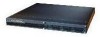
...DC units. To see translations of the DFCs. (See Figure 2-1.) Figure 2-1 Carrier Card With Two 8 PRI CT1 Cards 29032 Warning Before working on a chassis or working near power supplies, unplug the power cord on the Cisco AS5350 and Cisco...Installing Populated Carrier Cards Caution The carrier cards that accompanied this device. Cisco AS5350 and Cisco AS5400 Universal Gateway Card Installation Guide 2-2 78-13311-01 In any operator intervention....Chapter 2 Dial Feature Card and Carrier Card Guidelines • Universal access (analog modem or digital calls) is supported when an interface is ...
...DC units. To see translations of the DFCs. (See Figure 2-1.) Figure 2-1 Carrier Card With Two 8 PRI CT1 Cards 29032 Warning Before working on a chassis or working near power supplies, unplug the power cord on the Cisco AS5350 and Cisco...Installing Populated Carrier Cards Caution The carrier cards that accompanied this device. Cisco AS5350 and Cisco AS5400 Universal Gateway Card Installation Guide 2-2 78-13311-01 In any operator intervention....Chapter 2 Dial Feature Card and Carrier Card Guidelines • Universal access (analog modem or digital calls) is supported when an interface is ...

Installation Guide
Page 21
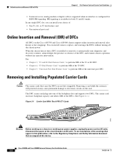
...network cables to the chassis until each screw is OFF, locate the circuit breaker on the Cisco AS5350 Chassis 36002 78-13311-01 Captive screw DFC Carrier card Captive screw Cisco AS5350 and Cisco AS5400 Universal Gateway Card Installation Guide 2-3 To remove a populated carrier card, follow the steps below: ...of the chassis. (See Figure 2-2 and Figure 2-3.) Figure 2-2 Loosen the Captive Screws on the panel board that services the DC circuit, switch the circuit breaker to the Regulatory Compliance and Safety Information document that secure the carrier card to avoid contact with...
...network cables to the chassis until each screw is OFF, locate the circuit breaker on the Cisco AS5350 Chassis 36002 78-13311-01 Captive screw DFC Carrier card Captive screw Cisco AS5350 and Cisco AS5400 Universal Gateway Card Installation Guide 2-3 To remove a populated carrier card, follow the steps below: ...of the chassis. (See Figure 2-2 and Figure 2-3.) Figure 2-2 Loosen the Captive Screws on the panel board that services the DC circuit, switch the circuit breaker to the Regulatory Compliance and Safety Information document that secure the carrier card to avoid contact with...
Installation Guide
Page 24
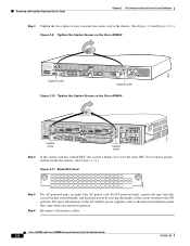
Cisco AS5350 and Cisco AS5400 Universal Gateway Card Installation Guide 2-6 78-13311-01 For more information on the Cisco AS5400 37162 Captive screw Captive screw Step 4 If the carrier card has a blank DFC slot, install a blank cover over the open DFC slot to the chassis installation guide that came with your universal... Figure 2-11.) Figure 2-11 Blank DFC Cover 36033 Step 5 Step 6 For AC powered units, reconnect the AC power cord. For DC powered units, remove the tape from the circuit breaker switch handle, and reinstate power by moving the handle of the circuit breaker to the...
Cisco AS5350 and Cisco AS5400 Universal Gateway Card Installation Guide 2-6 78-13311-01 For more information on the Cisco AS5400 37162 Captive screw Captive screw Step 4 If the carrier card has a blank DFC slot, install a blank cover over the open DFC slot to the chassis installation guide that came with your universal... Figure 2-11.) Figure 2-11 Blank DFC Cover 36033 Step 5 Step 6 For AC powered units, reconnect the AC power cord. For DC powered units, remove the tape from the circuit breaker switch handle, and reinstate power by moving the handle of the circuit breaker to the...
Installation Guide
Page 83
...for the E1 DFC 3-11 Connecting the 36-Pin Cable Connector to Twinax Interface Cable for the CT3 DFC 6-9 78-13311-01 Cisco AS5350 and Cisco AS5400 Universal Gateway Card Installation Guide IN-1 INDEX Numerics 2-Port or 4-Port T1 or E1 DFC LEDs (figure) 6-1 2-Port T1 or... DFC A-9 CT3, drop and insert mode 6-9 CT3 cable and port pinouts A-10 CT3 cable assembly (figure) A-10 customer equipment warning 3-9 D DC power disconnection warning 2-3 DFC, online insertion and removal 2-2 Dial Feature Cards, overview 2-1 documentation, getting xi document organization vii document organization (table)...
...for the E1 DFC 3-11 Connecting the 36-Pin Cable Connector to Twinax Interface Cable for the CT3 DFC 6-9 78-13311-01 Cisco AS5350 and Cisco AS5400 Universal Gateway Card Installation Guide IN-1 INDEX Numerics 2-Port or 4-Port T1 or E1 DFC LEDs (figure) 6-1 2-Port T1 or... DFC A-9 CT3, drop and insert mode 6-9 CT3 cable and port pinouts A-10 CT3 cable assembly (figure) A-10 customer equipment warning 3-9 D DC power disconnection warning 2-3 DFC, online insertion and removal 2-2 Dial Feature Cards, overview 2-1 documentation, getting xi document organization vii document organization (table)...
Installation Guide
Page 87
... equipment 3-9 DC power disconnection 2-3 ground connection first 1-2 installation instructions 1-2 lightning activity 2-3, 3-4, 3-9, 4-3, 4-5, 5-3, 5-7 power supply disconnection 2-2 product disposal 1-1 remove jewelry 1-2 telecommunications lines 3-9 Warning symbol, meaning of ix 78-13311-01 Cisco AS5350 and Cisco AS5400 Universal Gateway Card Installation Guide IN-5 Index troubleshooting, mixing WAN DFCs 6-5 TX MON, Bantam Jack 6-9 U universal port DFC (figure) 5-1 universal port DFC, overview 5-1 universal port...
... equipment 3-9 DC power disconnection 2-3 ground connection first 1-2 installation instructions 1-2 lightning activity 2-3, 3-4, 3-9, 4-3, 4-5, 5-3, 5-7 power supply disconnection 2-2 product disposal 1-1 remove jewelry 1-2 telecommunications lines 3-9 Warning symbol, meaning of ix 78-13311-01 Cisco AS5350 and Cisco AS5400 Universal Gateway Card Installation Guide IN-5 Index troubleshooting, mixing WAN DFCs 6-5 TX MON, Bantam Jack 6-9 U universal port DFC (figure) 5-1 universal port DFC, overview 5-1 universal port...
