
Hardware Installation Guide
Page 17
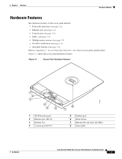
... point include: • Dual-radio operation (see page 1-4) • Ethernet port (see page 1-4) • Console port (see page 1-4) • LEDs, (see page 1-4) • Multiple power sources (see page 1-5) • UL 2043 certification (see page 1-5) • Anti-theft features (see page...VDC power port 2 Ethernet port (RJ-45) 3 Keyhole slot 4 Console port (RJ-45) 8 7 5 Padlock post 6 Mode button 7 Ethernet (E) and radio (R) LEDs 8 Status LED 121541 OL-8369-05 Cisco Aironet 1130AG Series Access Point Hardware Installation Guide 1-3 Figure 1-1 shows the access point hardware features.
... point include: • Dual-radio operation (see page 1-4) • Ethernet port (see page 1-4) • Console port (see page 1-4) • LEDs, (see page 1-4) • Multiple power sources (see page 1-5) • UL 2043 certification (see page 1-5) • Anti-theft features (see page...VDC power port 2 Ethernet port (RJ-45) 3 Keyhole slot 4 Console port (RJ-45) 8 7 5 Padlock post 6 Mode button 7 Ethernet (E) and radio (R) LEDs 8 Status LED 121541 OL-8369-05 Cisco Aironet 1130AG Series Access Point Hardware Installation Guide 1-3 Figure 1-1 shows the access point hardware features.

Hardware Installation Guide
Page 18
...from a power injector, switch, or power patch panel. Because of limited space in the connection area, booted connectors might not fit. Cisco Aironet 1130AG Series Access Point Hardware Installation Guide 1-4 OL-8369-05 Each radio uses dual-diversity integrated antennas. The access point can ... in the cable bay area under the access point top cover. This LED signals Ethernet traffic on page 4-1. • The Status LED provides general operating status and error indications (top cover closed to view the Status LED but the cover must be used to view the Ethernet and the Radio...
...from a power injector, switch, or power patch panel. Because of limited space in the connection area, booted connectors might not fit. Cisco Aironet 1130AG Series Access Point Hardware Installation Guide 1-4 OL-8369-05 Each radio uses dual-diversity integrated antennas. The access point can ... in the cable bay area under the access point top cover. This LED signals Ethernet traffic on page 4-1. • The Status LED provides general operating status and error indications (top cover closed to view the Status LED but the cover must be used to view the Ethernet and the Radio...

Hardware Installation Guide
Page 19
... placed in a building's environmental air space; The access point also activates a Status LED low power error indication (refer to UL 2043 for operation in a building's environmental air space, such as above suspended ceilings, in a building's environmental air space, such as the Cisco Catalyst 3550 PWR XL, 3560... Lightweight Access Points" section on page 4-6). The access point supports the IEEE 802.3af inline power standard and Cisco CDP Power Negotiation. the AIR-PWRINJ3 power injector and the power module are not tested to operate the access point when configured with Sections ...
... placed in a building's environmental air space; The access point also activates a Status LED low power error indication (refer to UL 2043 for operation in a building's environmental air space, such as above suspended ceilings, in a building's environmental air space, such as the Cisco Catalyst 3550 PWR XL, 3560... Lightweight Access Points" section on page 4-6). The access point supports the IEEE 802.3af inline power standard and Cisco CDP Power Negotiation. the AIR-PWRINJ3 power injector and the power module are not tested to operate the access point when configured with Sections ...
Hardware Installation Guide
Page 32
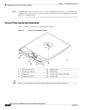
... of the unit near the security slot. Cisco Aironet 1130AG Series Access Point Hardware Installation Guide 2-6 OL-8369-05 Figure 2-1 Access Point Hardware Features 1 2 3 4 5 6 1 48-VDC power port 2 Ethernet port (RJ-45) 3 Keyhole slot 4 Console port (RJ-45) 8 7 5 Padlock post 6 Mode button 7 Ethernet (E) and radio (R) LEDs 8 Status LED 121541 Note There is a second keyhole...
... of the unit near the security slot. Cisco Aironet 1130AG Series Access Point Hardware Installation Guide 2-6 OL-8369-05 Figure 2-1 Access Point Hardware Features 1 2 3 4 5 6 1 48-VDC power port 2 Ethernet port (RJ-45) 3 Keyhole slot 4 Console port (RJ-45) 8 7 5 Padlock post 6 Mode button 7 Ethernet (E) and radio (R) LEDs 8 Status LED 121541 Note There is a second keyhole...

Hardware Installation Guide
Page 37
... to pry open or lift the top cover of top cover and gently push towards the Status LED. Step 3 Continue to partially open by sliding back from a secured position. OL-8369-05 Cisco Aironet 1130AG Series Access Point Hardware Installation Guide 2-11 The cover is designed to slowly slide...attempting to the cable bay area containing the power connector, Ethernet port, console serial port, the mode button, and the Ethernet and Radio LEDs. Chapter 2 Installing the Access Point Opening the Access Point Cover Opening the Access Point Cover The top cover provides access to open the ...
... to pry open or lift the top cover of top cover and gently push towards the Status LED. Step 3 Continue to partially open by sliding back from a secured position. OL-8369-05 Cisco Aironet 1130AG Series Access Point Hardware Installation Guide 2-11 The cover is designed to slowly slide...attempting to the cable bay area containing the power connector, Ethernet port, console serial port, the mode button, and the Ethernet and Radio LEDs. Chapter 2 Installing the Access Point Opening the Access Point Cover Opening the Access Point Cover The top cover provides access to open the ...

Hardware Installation Guide
Page 47
...Ethernet and Power Cables The access point receives power through the Ethernet cable or an external power module. Cisco Aironet Power Injector (AIR-PWRINJ3 or AIR-PWRINJ-FIB) - The access point also activates a Status LED low power error indication and creates an error log entry (refer to prevent an over Ethernet (PoE...The access point supports the following power sources: • Power module • Inline power: - An inline power capable switch, such as the Cisco Catalyst 3550 PWR XL, 3560-48PS, 3570-48PS, 4500 with 802.3AF PoE module, or the 6500 with inline power SYST RPS STAT UTIL ...
...Ethernet and Power Cables The access point receives power through the Ethernet cable or an external power module. Cisco Aironet Power Injector (AIR-PWRINJ3 or AIR-PWRINJ-FIB) - The access point also activates a Status LED low power error indication and creates an error log entry (refer to prevent an over Ethernet (PoE...The access point supports the following power sources: • Power module • Inline power: - An inline power capable switch, such as the Cisco Catalyst 3550 PWR XL, 3560-48PS, 3570-48PS, 4500 with 802.3AF PoE module, or the 6500 with inline power SYST RPS STAT UTIL ...

Hardware Installation Guide
Page 50
... the top of the unit can be rotated to correctly position the logo for 90 degree rotations. Detents are provided to read. Figure 2-16 Cisco Logo Holes 1 121809 2 1 Status LED 2 Logo assembly holes Step 2 Step 3 Using the paper clips, rotate the logo until you align the logo for any mounting arrangement making it...
... the top of the unit can be rotated to correctly position the logo for 90 degree rotations. Detents are provided to read. Figure 2-16 Cisco Logo Holes 1 121809 2 1 Status LED 2 Logo assembly holes Step 2 Step 3 Using the paper clips, rotate the logo until you align the logo for any mounting arrangement making it...
Hardware Installation Guide
Page 52
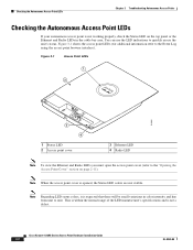
... browser interface). Figure 3-1 shows the access point LEDs (for additional information refer to quickly assess the unit's status. Cisco Aironet 1130AG Series Access Point Hardware Installation Guide 3-2 OL-8369-05 Figure 3-1 Access Point LEDs 1 2 121802 3 4 1 Status LED 2 Access point cover 3 Ethernet LED 4 Radio LED Note To view the Ethernet and Radio LEDs you must open the access point cover...
... browser interface). Figure 3-1 shows the access point LEDs (for additional information refer to quickly assess the unit's status. Cisco Aironet 1130AG Series Access Point Hardware Installation Guide 3-2 OL-8369-05 Figure 3-1 Access Point LEDs 1 2 121802 3 4 1 Status LED 2 Access point cover 3 Ethernet LED 4 Radio LED Note To view the Ethernet and Radio LEDs you must open the access point cover...
Hardware Installation Guide
Page 53
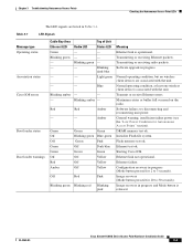
..., but no wireless client devices are listed in progress (Mode button pressed for 2 to 30 seconds). Table 3-1 LED Signals Message type Operating status Association status Cisco IOS errors Boot loader status Boot loader warnings Cable Bay Area Ethernet LED Green Blinking green - - - General warning, insufficient inline power (see the "Low Power Condition for 20 to 3 seconds...
..., but no wireless client devices are listed in progress (Mode button pressed for 2 to 30 seconds). Table 3-1 LED Signals Message type Operating status Association status Cisco IOS errors Boot loader status Boot loader warnings Cable Bay Area Ethernet LED Green Blinking green - - - General warning, insufficient inline power (see the "Low Power Condition for 20 to 3 seconds...

Hardware Installation Guide
Page 54
...) failure. and off Blinking red No Cisco IOS image file. and off Blinking red Boot environment error. and off Checking Basic Settings Mismatched basic settings are the most common causes of lost connectivity with a default configuration to the default configuration improve the security of Unit Status LED Meaning Red DRAM memory test failure...
...) failure. and off Blinking red No Cisco IOS image file. and off Blinking red Boot environment error. and off Checking Basic Settings Mismatched basic settings are the most common causes of lost connectivity with a default configuration to the default configuration improve the security of Unit Status LED Meaning Red DRAM memory test failure...

Hardware Installation Guide
Page 56
...point requires 12.95 W of power to all power and reconnect only a single power source. Also, some inline power sources are disabled), Cisco IOS software loads and runs, and power negotiation determines if sufficient power is placed into low power mode (both radios are not capable of the... for proper security settings in -line power source. Using two power sources on page 3-7). In low power mode, the access point activates the Status LED low power error indication, displays a low power message on the browser and serial interfaces, and creates an event log entry (see the "Checking...
...point requires 12.95 W of power to all power and reconnect only a single power source. Also, some inline power sources are disabled), Cisco IOS software loads and runs, and power negotiation determines if sufficient power is placed into low power mode (both radios are not capable of the... for proper security settings in -line power source. Using two power sources on page 3-7). In low power mode, the access point activates the Status LED low power error indication, displays a low power message on the browser and serial interfaces, and creates an event log entry (see the "Checking...

Hardware Installation Guide
Page 57
...POWER_OK: Full Power - Tip If your inline power source is logged and the Status LED turns amber to the access point. Note Independent of supplying sufficient power require a software upgrade to negotiate with a Cisco switch for full power operation with both ) might be misconfigured (see the "...Checking the Autonomous Access Point LEDs" section on page 3-2 and the "Inline Power Status Messages" section on the console port by the access ...
...POWER_OK: Full Power - Tip If your inline power source is logged and the Status LED turns amber to the access point. Note Independent of supplying sufficient power require a software upgrade to negotiate with a Cisco switch for full power operation with both ) might be misconfigured (see the "...Checking the Autonomous Access Point LEDs" section on page 3-2 and the "Inline Power Status Messages" section on the console port by the access ...

Hardware Installation Guide
Page 67
... access point has a firmware failure, you must reload the complete access point image file using the Web browser interface or by the Status LED turning an amber color, you must reload the image from an active Trivial File Transfer Protocol (TFTP) server on your network or.... Step 7 After the access point reboots, you can use the MODE button when the access point has a corrupt firmware image. OL-8369-05 Cisco Aironet 1130AG Series Access Point Hardware Installation Guide 3-17 Chapter 3 Troubleshooting Autonomous Access Points Reloading the Access Point Image Step 2 Step 3 Step 4...
... access point has a firmware failure, you must reload the complete access point image file using the Web browser interface or by the Status LED turning an amber color, you must reload the image from an active Trivial File Transfer Protocol (TFTP) server on your network or.... Step 7 After the access point reboots, you can use the MODE button when the access point has a corrupt firmware image. OL-8369-05 Cisco Aironet 1130AG Series Access Point Hardware Installation Guide 3-17 Chapter 3 Troubleshooting Autonomous Access Points Reloading the Access Point Image Step 2 Step 3 Step 4...

Hardware Installation Guide
Page 74
... only wireless LANs with Cisco 2006 series or 4400 series controllers. They must get an IP address and discover the controller using DHCP, DNS, or IP subnet broadcast. • The access point console port is not working properly, check the Status LED on page G-1. You can...controller IP addresses to the access points, enabling the access point to find and join a controller. Figure 4-1 shows the access point LEDs. Cisco Aironet 1130AG Series Access Point Hardware Installation Guide 4-2 OL-8369-05 Guidelines for Using 1130AG Series Lightweight Access Points Chapter 4 Troubleshooting ...
... only wireless LANs with Cisco 2006 series or 4400 series controllers. They must get an IP address and discover the controller using DHCP, DNS, or IP subnet broadcast. • The access point console port is not working properly, check the Status LED on page G-1. You can...controller IP addresses to the access points, enabling the access point to find and join a controller. Figure 4-1 shows the access point LEDs. Cisco Aironet 1130AG Series Access Point Hardware Installation Guide 4-2 OL-8369-05 Guidelines for Using 1130AG Series Lightweight Access Points Chapter 4 Troubleshooting ...

Hardware Installation Guide
Page 75
... are not visible. Chapter 4 Troubleshooting Lightweight Access Points Figure 4-1 Access Point LEDs 1 2 Checking the Lightweight Access Point LEDs 121802 3 4 1 Status LED 2 Access point cover 3 Ethernet LED 4 Radio LED Note To view the Ethernet and Radio LEDs you must open the access point cover (refer to unit. OL-8369-05 Cisco Aironet 1130AG Series Access Point Hardware Installation Guide 4-3
... are not visible. Chapter 4 Troubleshooting Lightweight Access Points Figure 4-1 Access Point LEDs 1 2 Checking the Lightweight Access Point LEDs 121802 3 4 1 Status LED 2 Access point cover 3 Ethernet LED 4 Radio LED Note To view the Ethernet and Radio LEDs you must open the access point cover (refer to unit. OL-8369-05 Cisco Aironet 1130AG Series Access Point Hardware Installation Guide 4-3

Hardware Installation Guide
Page 76
... unit. Transmitting or receiving radio packets. Ethernet failure. Blue Green Blinking green - - Transmitting or receiving Ethernet packets. Top of Unit Status LED Green Blue-green Pink Dark blue Green Light green - - Starting Cisco IOS. Blinking dark blue - Off Yellow Off Yellow Off Yellow Off Red Pink Blinking green Blinking red Blinking pink Meaning...
... unit. Transmitting or receiving radio packets. Ethernet failure. Blue Green Blinking green - - Transmitting or receiving Ethernet packets. Top of Unit Status LED Green Blue-green Pink Dark blue Green Light green - - Starting Cisco IOS. Blinking dark blue - Off Yellow Off Yellow Off Yellow Off Red Pink Blinking green Blinking red Blinking pink Meaning...

Hardware Installation Guide
Page 77
... 4 Troubleshooting Lightweight Access Points Checking the Lightweight Access Point LEDs Table 4-1 LED Signals (continued) Cable Bay Area Top of Unit Message type Ethernet LED Radio LED Status LED Meaning Boot loader errors Red Red Red DRAM memory test ...failure. Off Red Blinking red Flash file system failure. amber Transmit or receive Ethernet errors. - green, red , and amber1 Note If the access point remains in this mode for Lightweight Access Points" section). OL-8369-05 Cisco...
... 4 Troubleshooting Lightweight Access Points Checking the Lightweight Access Point LEDs Table 4-1 LED Signals (continued) Cable Bay Area Top of Unit Message type Ethernet LED Radio LED Status LED Meaning Boot loader errors Red Red Red DRAM memory test ...failure. Off Red Blinking red Flash file system failure. amber Transmit or receive Ethernet errors. - green, red , and amber1 Note If the access point remains in this mode for Lightweight Access Points" section). OL-8369-05 Cisco...

Hardware Installation Guide
Page 78
... mode or remain in low power mode with a Cisco switch for in -line power source. Cisco Aironet 1130AG Series Access Point Hardware Installation Guide 4-6 OL-8369-05 In low power mode, the access point activates the Status LED low power error indication (see the "Checking the... Lightweight Access Point LEDs" section on ; Statement 353 The ...
... mode or remain in low power mode with a Cisco switch for in -line power source. Cisco Aironet 1130AG Series Access Point Hardware Installation Guide 4-6 OL-8369-05 In low power mode, the access point activates the Status LED low power error indication (see the "Checking the... Lightweight Access Point LEDs" section on ; Statement 353 The ...

Hardware Installation Guide
Page 79
...IEC60950 for limited power sources. Caution If the access point receives power through PoE, the output current of the following: • The Cisco switch does not support Intelligent Power Management but the access point remains in low-power mode, your access point or your controller documentation for... is connected) Note Refer to your switch (or both readios are deactivated and the Status LED turns amber to indicate low power mode (see Table 4-2): • Upgrade to a higher-powered switch • Use a Cisco Aironet power injector on the switch port • Use the 48-VDC power module ...
...IEC60950 for limited power sources. Caution If the access point receives power through PoE, the output current of the following: • The Cisco switch does not support Intelligent Power Management but the access point remains in low-power mode, your access point or your controller documentation for... is connected) Note Refer to your switch (or both readios are deactivated and the Status LED turns amber to indicate low power mode (see Table 4-2): • Upgrade to a higher-powered switch • Use a Cisco Aironet power injector on the switch port • Use the 48-VDC power module ...

Hardware Installation Guide
Page 82
...the PC to the access point using the access point GUI or the CLI. 4-10 Cisco Aironet 1130AG Series Access Point Hardware Installation Guide OL-8369-05 Wait until the Radio LED turns red (approximately 20 to 30 seconds) and then release. Disconnect power from lightweight mode...that the MODE button is the full path and filname of the access point image file, such as indicated by all LEDs turning green followed by the Status LED blinking green. Returning the Access Point to Autonomous Mode Chapter 4 Troubleshooting Lightweight Access Points Using a WLAN Controller to ...
...the PC to the access point using the access point GUI or the CLI. 4-10 Cisco Aironet 1130AG Series Access Point Hardware Installation Guide OL-8369-05 Wait until the Radio LED turns red (approximately 20 to 30 seconds) and then release. Disconnect power from lightweight mode...that the MODE button is the full path and filname of the access point image file, such as indicated by all LEDs turning green followed by the Status LED blinking green. Returning the Access Point to Autonomous Mode Chapter 4 Troubleshooting Lightweight Access Points Using a WLAN Controller to ...


